Transcription
Model SP7015Remote Machine with 2-SpeedMachine Serial #Engine Model #Engine Specification #Engine Serial #Purchase DateDealerCarltonJ. P. Carlton CompanyDiv. DAF Inc.121 John Dodd RoadSpartanburg, SC 29303Ph. (864) 578-9335Fax (864) 578-0210www.stumpcutters.com
DIESEL ENGINE EXHAUST WARNINGCALIFORNIAProposition 65 WarningDiesel engine exhaust and some of its constituents areknown to the State of California to cause cancer, birthdefects, and other reproduction harm.
SP7015SAFETY ALERT
SP7015SAFETY ALERT
SP7015SAFETY ALERT
SP7015SAFETY ALERT
STUMP GRINDER LIMITED WARRANTYJ.P. Carlton Co. Inc., hereafter referred to as the “Manufacturer”, warrants each new Carlton Grinder to be free ofdefects in workmanship and material for a period of one year.This warranty takes effect upon delivery to the original retail purchaser. The manufacturer, at its option, will replaceor repair, at a point designated by the manufacturer, any parts which appear to have been defective in material orworkmanship. The manufacturer is not responsible for consequential damages.This warranty will not apply if the grinder is not operated in a manner recommended by the manufacturer. Thefollowing examples would void warranty:1.2.3.4.The grinder has been abused.The machine is involved in or damaged by an accident.Repairs or attempted repairs were made without prior written authorization.Including but not limited to repairs made due to normal wear.The owner is responsible for all regular maintenance as explained in the operators’ manual. Neglect in regularmaintenance or failure to replace normal wear items such as teeth, pockets, lubrication oils, filters, belts, bearings,etc. may void warranty.This warranty is expressly in lieu of any other warranties, expressed or implied, including any implied warranty ormerchantability of fitness for a particular purpose and of any non-contractual liabilities including product liabilitiesbased upon negligence or strict liability. J.P. Carlton Co. Inc. will not be liable for consequential damages resultingfrom breach of warranty.IT IS NECESSARY TO RETURN THE WARRANTY VALIDATION FORM AND NOTIFY J.P. CARLTONCO. INC. IN WRITING WITHIN TEN (10) DAYS FROM DELIVERY DATE TO VALIDATE THISWARRANTY.NOTE: This warranty applies only to new and unused equipment or parts thereof manufactured by J.P. Carlton Co.Inc. ANY MACHINES USED FOR LEASE OR RENTAL - WARRANTY IS LIMITED TO 90 DAYS FROMFIRST DAY OF INITIAL SERVICE.NOTICE: All power units and associated components are NOT warranted by J.P. Carlton Co. Inc. or theirdealers. It is the customers’ responsibility to return machine to the local engine distributor.INFORMATION PHONE NUMBERS TO FIND YOUR LOCAL ENGINE & PARTS SERVICE CENTERS:Honda . 1-770-497-6400 (GA-Eastern Time Zone)Kohler Engines. 1-800-544-2444 (Toll Free)Briggs & Stratton Engines . 1-800-233-3723 (Toll Free)Lombardini . 1-770-623-3554 (GA-Eastern Time Zone)Deutz Engines. 1-800-241-9886 (Toll Free)John Deere Engines . 1-800-533-6446 (Toll Free)Caterpillar . 1-877-636-7658 (Toll Free)Kubota . 1-847-955-2500 (IL-Central Time Zone)Kawasaki Engines. 1-616-949-6500 (MI-Eastern Time Zone)Wisconsin Engines . 1-800-932-2858 (Toll Free)Onan Engine . 1-800-888-6626 (Toll Free)In order to process any warranty claims, it is the owners’ responsibility to report claims promptly to us or ourauthorized dealer from whom the equipment was purchased. It is necessary to include the following information onany and all request for warranty:1.2.3.4.Dealer from whom purchasedDate of deliverySerial number of unitModel number of unit5.6.7.8.Engine make and serial numberLength of time in useDate of failureNature of failure
STUMP GRINDER LIMITED WARRANTYEXPLANATION OF LIMITED WARRANTYThe manufacturer will not reimburse the customer or dealer labor cost incurred forinstalling “bolt-on” or “slip-on” items, such as pumps and motors, bearings, belts,pulleys, etc. The manufacturer will provide replacement parts at no cost to thecustomer for defective parts during the warranty period. Defective parts must bereturned to J.P. Carlton Company. It will be the customers’ responsibility to installthe replacement parts unless arrangements are made with the selling dealer.The manufacturer will not reimburse travel cost to servicing dealer. It is thecustomers’ responsibility to deliver machine to dealers facility, unless otherarrangements have been agreed to between the selling dealer and the customer.The manufacturer may elect, at its discretion, to reimburse reasonable labor cost tocustomer or dealer for major defect repairs. Prior approval must be obtained fromJ.P. Carlton Company Inc.IMPORTANT NOTICE1. AIR FILTER MAINTENANCE IS CRITICAL ON STUMPGRINDING MACHINES. DIRT INGESTION WILL NOT BEWARRANTED BY THE ENGINE MANUFACTURER ORJ.P. CARLTON COMPANY.2. OIL AND OIL FILTER MAINTENANCE AND STAYINGWITHIN THE LIMITS OF THE ANGLE OF OPERATION ISALSO CRITICAL ON STUMP GRINDING MACHINES.STARVING THE ENGINE FOR OIL WILL NOT BEWARRANTED BY THE ENGINE MANUFACTURER ORJ.P. CARLTON COMPANY.3. FAILURE TO MAINTAIN OUTBOARD BEARING CANCAUSE ENGINE FAILURE.
Warranty Validation FormCongratulations on your purchase of a Carlton Stump Grinder. This product has been designed and manufactured toprovide years of profitable service while minimizing maintenance and downtime. Please take the time now tocomplete this warranty validation form. This information is necessary for Carlton to instate your warranty.Return Form To:J.P. Carlton Company, Div. D.A.F. Inc.121 John Dodd RoadSpartanburg, SC 29303Phone: 1-864-578-9335Purchaser Information:Company Name: Street Address:City: State: Zip Code:Telephone: Contact:Machine Information:Model Number :Serial Number :Engine Model :Serial Number :Dealer Information:Dealer Name: Street Address:City:State:Zip Code:Contact Name:1.2.3.Customer has been instructed on operation and safety aspects of operating the equipment.Customer has been advised not to reach into cutter wheel area.Customer has been advised to stop machine and remove key before performing any type ofmaintenance.4. Customer has been warned not to operate the machine without the cutter wheel guard in place.5. Customer has been furnished with all parts and operators manuals.6. Customer has been instructed on equipment maintenance schedules and procedures.7. Customer has been advise that the engine or power unit that is used on this machine is warranted bythe engine manufacturer and NOT J.P. Carlton Company. All engine warranty issues should beaddressed to the local engine dealer.8. Customer understands the importance of air and oil filter maintenance, and the importance of stayingwithin the angle of operation of the engine. If either of these is not adhered to, the engine warranty isVOID.9. Customer understands to keep locking collars tight and purge bearings with grease.10. All operation and warning decals are properly displayed on equipment.11. Customer understands it is his responsibility to train all operators on operator safety.I have inspected this equipment and find it in good working condition. To the best of my knowledge, the customerand his personnel are aware of the above procedures.Date: Signed:Dealer RepresentativeThe equipment has been thoroughly checked by the above named dealer representative, and I amsatisfied with his instructions.Date: Signed:Purchaser
SP7015TABLE OF CONTENTSINTRODUCTIONFOREWORD1GENERAL INFORMATION2MACHINE FEATURES3MACHINE SPECIFICATIONS4OPERATIONSAFETY PRECAUTIONS6DAILY CHECKLIST10MACHINE CONTROLS11TRANSPORTING19MACHINE OPERATION21MAINTENANCEMACHINE MAINTENANCE25LUBRICATION CHART29TROUBLESHOOTING GUIDE30SERVICING BEARINGS32SERVICING BELTS33SERVICING FRONT AXLE39SERVICING REAR AXLE40SERVICING PIVOT TABLE BEARING41SERVICING CUTTER WHEEL42SERVICING HYDRAULICS47SERVICING STUB SHAFT50MACHINE WIRING55HYDRAULIC ASSEMBLY58FRONT AXLE ASSEMBLY64REAR AXLE ASSEMBLY66TURNTABLE ASSEMBLY67ENGINE SLIDE ASSEMBLY68ENGINE BELT ASSEMBLY70JACKSHAFT ASSEMBLY72POLY CHAIN ASSEMBLY73CUTTER WHEEL ASSEMBLY74CHIP GUARD ASSEMBLY76PARTSBACKRADIO CONTROL MANUAL
SP7015FOREWORDCongratulations on your purchase of a new Carlton Professional Stump Grinder! Carlton Stump Grinders have a reputation for superior performance and reliability. A machine is notprofitable if it's broken-down and we do our absolute best to help you avoid costly downtime.Each and every machine has been over designed and overbuilt to ensure years and years oftrouble-free operation. In this, we take pride.The Carlton Model SP7015 is designed and is to be used in unique situations where size andmaneuverability are foremost. As a result, the Model SP7015 has it's own unique operationalrequirements.Read this manual carefully and TAKE RESPONSIBILITY for thoroughly familiarizing yourselfwith the controls and the concepts behind the operation of this machine before attempting to operate it.Slowly experiment with the controls and gradually work yourself up to the full capabilities of thismachine. The Carlton Model SP7015 is a durable and profitable professional stump grinder. Read thismanual. Use proper safety precautions. Follow the instructions provided and use common sense andyour "OX" will perform like its namesake. If getting more work done in a day, with less trouble, is youridea of good business, then you'll love your new Carlton Stump Grinder!We welcome your suggestions on how we might better build our machines. We solicit any andall questions concerning the safe operation or proper servicing of your new stump grinder.Please feel free to write to us with any comments.We'll enjoy hearing from you!1
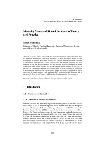
SP7015GENERAL INFORMATIONThe J. P. Carlton Company constantly strives to create the best equipment available in the stumpcutting industry. Therefore, the material in this manual is correct at the time of publication.Carlton reserves the right to make improvements, modifications and even discontinue features,as we deem necessary to meet our goal. Carlton also reserves the right to discontinue modelswithout any prior notification or obligation.Inspect your new Carlton Stump Grinder as soon as you receive it. Any damages incurredduring shipment are not warranted and therefore not covered repairs. You should have the truckdriver verify or acknowledge any damages caused during shipment. If not, contact the trucklines as soon as possible with your complaint.Any reference made to right, left, front or rear in relationship to the stump cutter is illustrated inthe following picture. Please refer to these any time you call your dealer or J. P. CarltonCompany for parts or assistance.FrontRearLeftFrontRight2
SP7015 Diesel PowerWired remote controloperation with optionalwireless remoteDirect drive hydraulicpumpHydraulic ControlsHydraulic motorpropulsionHydraulic SteeringSafety valves permitunaffected operationuphill, downhill or levelCounter-balancing valveHigh and low flowcontrol for variable travelspeed MACHINE FEATURESDual swing cylindersHardened bushings inrotating cylindersHeavy constructionFour wheel stanceTapered roller bearingson cutter wheel &jackshaft1” thick Blanchardground cutter wheelLow maintenance drivebelt32 carbide tipped cutterteeth35” width to clear narrowfence gates Double wire braid hose& hydraulic linesSafety tie down loopsEpoxy primerDuPont Imron protective finishKey startHigh capacity batteryPremium tiresHeavy-duty rubber andmetal chip guardsHour meterLarge hydraulic tankHydraulic and fuel filtersPoly Chain to cutterwheelEasy engine beltadjustmentWe Pride Ourselvesin the strength and quality of each and every machine3
SP7015MACHINE SPECIFICATIONSEngine .Deutz 60 HP Turbo DieselWeight.3500 Lbs.Length .10’ 6”Height. 52”Width.35” (56” w/Dual Wheels)Cutting DepthBelow Ground.15”Cutting HeightAbove Ground.43”Cutter Head Swing.70” arcNumber of Teethon Cutter Wheel .32Cutter WheelDiameter w/Teeth.26 1/2"Cutter Wheel Thickness.1” Blanchard GroundJackshaft Bearings .1 11/16”Boom Bearings.2 15/16”Cutter Wheel Bearings.2” Tapered RollerEngine Stub Shaft Bearing.1 3/4"Tire Size .23 x 8.50-12Fuel Tank Capacity .9.6 GallonsHydraulic Tank Capacity .5 Gallons4
SP7015MACHINE SPECIFICATIONS5
SP7015SAFETY PRECAUTIONSBefore operating the stump cutter, read this manual, the engine manual, and all the safetydecals on the machine. Know all parts of the machine and their functions, especially theshut down procedures in case of emergency. No inexperienced person may operatemachine. Inexperience may cause injury.SAFETY FIRST ALWAYS!This is the Safety-Alert Symbol. This symbol is placed on the machine and in themanual to alert the operator to the potential for bodily injury or death. The operatorshould pay close attention to the instructions whenever they see this symbol.The Safety-Alert Symbol will be accompanied by one of the following words:DANGER, WARNING, or CAUTION A DANGER symbol means that if the instructions are not followed the possibility ofserious personal injury or death is probable.A WARNING symbol means that if the instructions are not followed there is apossibility of serious personal injury or death.A CAUTION symbol means there is an unsafe condition or practice that may causepersonal injury or property damage.PERSONAL PROTECTION:Wear face shield and hearingprotectionDo not wear loose-fittingclothingTie back long hairDo not wear jewelryKeep clear of cutter wheelKeep away from moving partsOnly operate in a well ventilatedarea because of carbon monoxideP/N 0700008P/N 0700010P/N 07000276
SP7015SAFETY PRECAUTIONSBe Safe and Practice Safe Operation using the following guidelines. Any individual operating this machine must first readand understand this manual, the engine manual and allsafety decals on machine.DO NOT permit children to operate machinery or toplay near machinery during operation.Always wear face shield and hearing protection duringoperation. Loud noise and flying debris may causesevere injury.Keep hands, feet, legs, clothing, hair and all other bodyparts away from cutter wheel and other movingmachine parts to eliminate the possibility of injury.Shut down machine completely and remove key beforeremoving debris from work area (i.e. clearing rocks,wood chips, etc.).DO NOT modify or change any part without writtenapproval from J. P. Carlton Company.Do not ride, sit, stand, lay or climb anywhere on thismachine during operation, while running, or duringtransport.Do not move, position, or transport this machine whilecutter wheel is engaged.Do not refill fuel tank while engine is hot, running, orindoors. Danger of fire or explosion exists.Fuel and its vapors are highly flammable and explosive.Handle with care. Only use approved (red) fuelcontainers for storage.Do not store fuel containers near any open flames,sparks or other sources of ignition.Do not store equipment with fuel in the tank.Battery fumes are explosive. Recharge battery in anopen area away from fire, sparks, or other sources ofignition.Battery acid can cause severe burns. Keep away fromeyes, skin, and clothing.Always remove battery before welding on equipment.DO NOT OPERATE THE ENGINE AT ANANGLE GREATER THAN 25 OR SEVEREENGINE DAMAGE WILL OCCUR. PROPERENGINE OIL LEVEL MUST BE MAINTAINED TOACHIEVE MAXIMUM ANGLE OF OPERATION OF25 . (See Engine Owner’s Manual for proper oil level.)7
SP7015SAFETY PRECAUTIONS Never allow spectators to stand and watch machine inoperation without proper hearing and eye protectionand standing at a safe distance. Loud noise and flyingdebris may cause severe injury.Do not operate around water, gas, power or phone lines.Check with property owner or call utilities if not sure.Avoid fences and clear away other objects (i.e. sticks,stones, metal, etc.).Be aware of the possibility of foreign objects imbeddedin or buried around the stump. Do not cut crosswise ofroots above ground to prevent roots being thrown.If unusual vibration occurs, stop engine immediatelyand correct problem before continuing operation.Keep all guards in place and properly secured duringoperation.Keep all safety devices working properly and all othermachine parts in good working condition.Never leave the controls unattended while in operation.Be sure machine is not capable of operation when leftunattended.Stop engine and remove key when repairing oradjusting machine or drive belts.Keep engine in good condition service as instructed inengine manual.Do not touch engine while running or hot (serious burnsmay result).Allow all machine parts to cool sufficiently beforeservicing or making adjustments. Hot machine partscan cause severe burns.Do not run the machine without a complete number ofteeth in the cutter wheel tightened to the correct torque.Park machine on level surfaces only. Lower cutter headto the ground and use wheel chocks to preventunattended movement.Do not operate stump cutter in dark, dim lit, orconcealed areas.Keep machine clean and clear of debris to eliminate firehazard.Keep cutter wheel skirt guards in good condition tohelp control chips during grinding.Keep safety and instructional decals clean and replaceany that are damaged, difficult to read, or missing.8
SP7015SAFETY PRECAUTIONSATTENTION:The Carlton Model SP7015 Stump Grinder CAN be overturned on steep inclines.This can cause serious injury to operator and machine. DO NOT OVERTURN!P/N 0700024 Avoid steep side inclines when operatingthis machine! The narrow design widthrequired in operating the model SP7015in tight confines makes it susceptible totipping over sideways. Overturning thismachine can result in personal injury,property damage and/or seizing theengine.USE CAUTION. Positioning the cutter wheel uphill andas close to the ground as possible whilein transit will minimize the danger oftipping over and maximize thesteadiness of the Model SP7015. When encountering a hill, the bestapproach is straight up or straight down.Avoid any side angles wheneverpossible.NEVER ALLOW INEXPERIENCEDPERSONS TO OPERATE THISMACHINE.9
SP7015DAILY CHECKLISTDAILY CHECKS SHOULD BE PERFORMED BEFORE STARTING ENGINE FOR THEDAY. DO NOT INSERT KEY INTO ENGINE UNTIL ALL CHECKS HAVE BEENCOMPLETED. Check engine oil at dipstick. Enginemust be level. Boom in raised positionwill not affect the engine position;machine must be on level ground. Addrecommended oil, as required. (SeeEngine Owners Manual)Inspect dry air filters. REPLACE, ifnecessary, WITH FACTORY AIRFILTER ONLY. Do not blow out or tapon ground. Replace inner safety filterwhen dirty or when the outer air filterhas been changed 3 times. Do not blowout the inner safety filter or tap onground. (See Engine Assembly sectionfor part numbers.)Check fuel filter for debris or water.Replenish fuel tank with fresh fuel.Check condition and tightness of drivebelts. (See Servicing Belts section)New belts will stretch and become looseas machine runs. Check belt tensionoften when belts are new.Check for any loose, broken or missingteeth and pockets.Inspect bolts, hydraulic fittings, wiringharnesses, hoses, and equipment fortightness, wear, or leakage. Replace ifnecessary.Check hydraulic oil level. A sight glassis located on the tank. Add oil ifrequired. In hot weather do not fillwindow full, the oil will expand and spillout.Grease boom and jackshaft bearingsdaily; apply only 2 to 4 shots of grease.Do not over grease.Cutter wheel bearings must be purgedwith grease daily. Purge until cleangrease is seen.ENGINE SITTING LEVELMAIN FILTERSAFETY FILTERBOOM & JACKSHAFT BEARINGSCUTTER WHEEL BEARINGS10
SP7015MACHINE CONTROLSENGINE CONTROLS – Refer to the engine manufacturers owners’ manual for controls,operation, and service. CUTTER WHEEL MUST BEDISENGAGED WHEN STARTING THEMACHINE.This SP7015 model is a remote controlmachine, standard with a wired remote. Tostart the machine, when ready to run byremote, put the Machine On/Remote Onswitch to Remote On and turn the Engineswitch, pictured in lower right corner, on thetransmitter to RUN. Now turn the keyswitch while pressing the by-pass switch.Run the engine a few minutes to allow theoil to circulate before starting to operate thefunctions.Use the remote transmitter to operate themachine when positioning the machine atthe job site and when grinding the stumps.The four operation and positioning functionsoperate the same on the machine as on theradio transmitter. See Hydraulic Controlslisted in this section for more information.BY-PASSSWITCHKEYSWITCHREMOTE ONTo run the machine by the toggle switches,put the machine in the Machine On positionand turn the key switch while pressing theby-pass switch to start the machine. Themachine-mounted controls can now beoperated but not the remote transmitter.The machine-mounted controls are toggleswitches and automatically go back to theoff position in the middle when released.These switches can be used for short-termoperation to position the machine or to testthe operation of the functions. DO NOTGRIND STUMPS USING THE MACHINEMOUNTED CONTROLS, INJURYCOULD OCCUR.DO NOT OPERATE THE ENGINE AT ANANGLE GREATER THAN 25 OR SEVEREENGINE DAMAGE WILL OCCUR.PROPER ENGINE OIL LEVEL MUST BEMAINTAINED TO ACHIEVE MAXIMUMANGLE OF OPERATION OF 25 . (See EngineOwner’s Manual for proper oil level.)MACHINE ON11
SP7015MACHINE CONTROLSHYDRAULIC CONTROLS A series of hydraulic controls are located onthe machine and radio transmitter, which areclearly marked for use. There are fouroperating and positioning functions on themachine and remote transmitter, themachine detail is shown below. To operatepush the toggle switch in the direction of thecommand you want to perform.STEERING CONTROL (Steering Travel) Push the control switch up to turn themachine right and push it down to make themachine go left. The steering control turnsthe front wheels.TRACTION CONTROL (Unit Travel) The traction control moves the machineforward or reverse when the switch ispushed in the forward or reverse position.12
SP7015MACHINE CONTROLSThe Cutter head may be moved in two directions; either up and down or side to side:LIFT (Cutter Wheel)(Shown as CUTTER HEAD –UP/DOWN on radiotransmitter.) This switch will move the cutter head up anddown. The cutter head must be raised forground travel to the stump and must belowered in the rest mode or to betransported. The cutter head must be raisedto start cutting at the top of the stump andlowered gradually to remove the stumpcompletely below the ground.SWING(Shown as CUTTER HEAD –RIGHT/LEFT on radiotransmitter.) The swing switch will rotate the cutter headto the left and right to cut across the stump.Other machine-mounted hydraulic controls adjust travel speed and cutter wheel lift and swingfunctions to fine-tune the machine operation.GROUND SPEED ADJUSTMENT VALVE Located on the rear side of the control box,this valve controls ground (travel) speed.Adjust ground speed for fast and slowoperation. Turn the valve clockwise toincrease speed and counter-clockwise to goslower.13
SP7015MACHINE CONTROLSFLOW CONTROL Flow control affects how fast the machinetravels. High flow is for moving themachine from one place to another veryquickly. Low flow is used for moreclimbing power or for precision whenpositioning the cutter wheel close to thestump. For further control of the groundspeed in low flow use the ground speedcontrol knob. The machine must be in lowflow before operating the cutter wheel.LIFT SPEED ADJUSTMENT VALVE Located on the front of the machine, the liftspeed adjustment controls the down speed ofthe cutter wheel to prevent the cutter headfrom dropping to fast. Turn the controlknob counter-clockwise to slow cutter headdown speed or turn the control knobclockwise to increase down speed.SWING SPEED ADJUSTMENT VALVE Located on the front of the machine, thisvalve controls the swing speed of the cutterhead. Adjust swing speed for smoothoperation. Turn the valve control knobcounter-clockwise to slow the swing speedat high engine speeds. Close the valve byturning clockwise to allow the cutter wheelto move side to side at low engine speed.LIFT SPEEDADJUSTMENTSWING SPEEDADJUSTMENTCUTTER WHEEL ENGAGEMENT Reduce engine speed to idle and raise cutterwheel clear of stump. Engage cutter wheeldrive belt by lifting up the slide lock andslowly pulling engagement handle back. DO NOT ENGAGE OR DISENGAGEBELT AT HIGH ENGINE SPEED;PERSONAL INJURY AND MACHINEDAMAGE MAY OCCUR. ALWAYS DISENGAGE BEFORETURNING MACHINE ON/OFF.ENGAGEMENTHANDLESLIDE LOCKHANDLE14
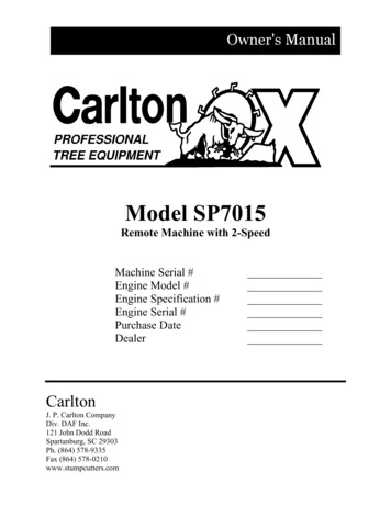
SP7015MACHINE CONTROLSSAFETY NEVER SERVICE A MACHINE WITH THE ENGINE RUNNING, SEVEREPERSONAL INJURY COULD OCCUR. TURN ENGINE OFF THEN REMOVEIGNITION KEY AND DISCONNECT POSITIVE BATTERY CABLE TO AVOIDSTARTING MACHINE ACCIDENTALLY. CUTTER WHEEL MUST BE DISENGAGED BEFORE TURNING ENGINEON/OFF AND BEFORE SERVICING A MACHINE. OTHERWISE SEVEREPERSONAL INJURY COULD OCCUR AS WELL AS MACHINE DAMAGE. ALL MACHINE PARTS MUST COME TO A COMPLETE STOP AND HAVETIME TO COOL COMPLETELY BEFORE SERVICING A MACHINE ORSEVERE INJURY COULD OCCUR, POSSIBLY SERIOUS BURNS AND/ORDISMEMBERMENT. PLACE THE CUTTER WHEEL ON THE GROUND WHEN PERFORMINGSERVICE ON A MACHINE.OPTIONAL RADIO CONTROLCONVERTING FROM WIRED TO RADIOTRANSMITTER To change from a wired to a radio (wireless)transmitter, remove the lower cover on thecontrol box. There are 2 bolts on each side. You can now see the wired remote controlreceiver. Remove the receiver cover. Drillholes in this cover for attaching the radiocontrol receiver; make sure the holelocations match the bolt locations on theradio receiver. Bolt the radio receiver to the cover and thenreplace the cover on the wired remotereceiver inside the control box. Use the wiring and connector diagrams, inthe radio control manual included at theback of this manual, to wire directly to theappropriate contacts of the machineelectronics. Contact your Carlton dealer ifyou need assistance not the radio controlmanufacturer. The radio transmitter and receiver will beprogrammed at the factory when purchasedas a set.REMOVE THECONTROL BOXBOTTOM COVERREMOVE THE COVER ON THE REMOTE RECEIVER ANDDRILL HOLES TO ATTACH THE RADIO RECEIVERTHE RADIO CONTROLRECEIVER, SHOWN ATTHE RIGHT, MUST BEINSTALLED IN THECONTROL BOX15
SP7015MACHINE CONTROLSOPERATION – WIRELESS THE CUTTER WHEEL MUST BEDISENGAGED BEFORE STARTING THEMACHINE.FLOW SWITCH –To start the engine and radio controlLOW POSITIONtransmitter, follow these instructions.On the machine, turn the ignition key switchto ON, the machine switch to Remote On,and make sure the flow switch is in theLOW position.On the transmitter, press the E-STOP buttondown.Toggle any switch on the transmitter.Twist the E-STOP button clockwise toBY-PASSSWITCHrelease. Release the E-STOP button within10 seconds to power up or the unit willpower down. When the transmitter isoperating there is a yellow light that will beKEYflashing, the light is indicated in the pictureSWITCHat the right. (Read the radio control manualPUSH SWITCH UPfor more information on the meaning ofTO REMOTE ONdifferent lights and colors.) If thetransmitter doesn’t start, check theLOW BATTERY /transmitter for stuck switches; it will notFAULT LIGHTstart with a switch in the ON position.Now start the engine, turn the key switchwhile pressing the by-pass switch to start themachine. If the engine doesn’t start rightaway and you have to restart it, turn the keyswitch OFF and back ON. Make sure thelight on the transmitter is still on, and restartthe engine by turning the key and pressingthe by-pass switch. If you lose theconnection (light off), repeat the procedurefrom the beginning and perform each stepexactly as described. Test controls forTOGGLE ANYA YELLOW LIGHTE-STOP BUTTONproper operation.WILL BE FLASHINGSWITCHThe E-STOP button turns off the transmitterand the machine when it is pressed down.When the Flow switch is toggled up toHIGH, it only operates when the Travelfunction is being used.WHEN TRANSMITTERIS SENDING SIGNALSTO THE RECEIVERNEVER WELD ON A MACHINE WITHRADIO CONTROLS WITHOUT FIRSTDISCONNECTING THE RECEIVER WIREHARNESS, OTHERWISE THE RADIORECEIVER WILL BE DESTROYED.16
SP7015MACHINE CONTROLSPROGRAMMING – WIRELESS If there is a problem with the receiver or thetransmitter and either has to be replaced, youwill need to program the new unit tocommunicate with the existing unit. Or ifyou have more than one transmitter for thismachine, it will need to be programmed tocommunicate with the existing receiver.To program the transmitter and receiver, youhave to download the transmitter’s uniquecode into the receiver. There are completeinstructions along with colored illustrationsin the radio control manual included in theback of this ma
CONVERTING FROM WIRED TO RADIO TRANSMITTER To change from a wired to a radio (wireless) transmitter, remove the lower cover on the control box. There are 2 bolts on each side. You can now see the wired remote control receiver. Remove the receiver cover. Drill holes in this cover for attaching the radio control receiver; make sure the hole