Transcription
EIT/FE ExamEE ReviewProf. Richard SpencerBasic Electricity Outline Charge, Force, Electric Field, Work and EnergyWork, Energy and VoltageThe AtomCurrent, Resistance and Ohm’s LawPower and EnergyConductors, Resistors and InsulatorsSchematics & modelsDC Circuits1
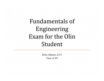
Force between Two ChargesCharge 1Charge 2r Consider two charges separated by a distance r The force on charge 2 because of charge 1 is:F2 Q1Q2a r124πε r 2 Just like gravity!Electric FieldCharge 1Charge 2E1 We sometimes find it convenient to picture theeffect one charge has on another by defining anelectric field vector The electric field at point 2 due to the charge at 1isQ1E1 a r124πε r 2QQ And the force is then given by F2 Q2E1 1 22 a r124πε r2
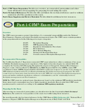
Electric FieldCharge 1Charge 2r12Net force(or field)r32Charge 3 If there are more charges, the fields and forces addas vectorsE E ENet13FNet F1 F3 Q2 ( E1 E3 )Electric Field and VoltageCharge 1Charge 2rE1r It takes work to move a charge in a field For example, the work required to move Charge 2to the left isr′r′r′Q1dr Q1Q2 drW Q2 E1dr Q2 4πε r 24πε r r 2rr Q1Q2 1 1 4πε r ′ r 3
Electric Field and VoltageCharge 1Charge 2E1 Because it takes work to move a charge in a field,charge possesses electrical potential energy whenin a field Voltage is the electrical potential energy per unitcharge and is always measured as the difference inpotential energy between two points – if a secondpoint is not explicitly stated, one has beenassumed (e.g., ground)– Note that potential only makes sense for a conservativefield!Electric Fields We saw that the field from a pointcharge is given byCharge 1Q1a r124πε r 2 The field from an infinitely longline of charge isE1 EL ρLar2πε r The field from an infinite sheet of charge isES ρSaz2ε4
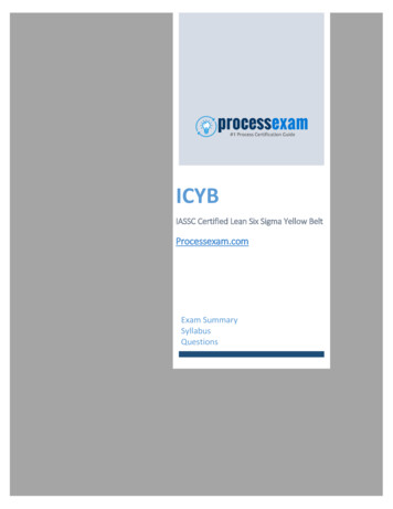
Summary: Consider Test Charge Consider a spatial distribution of charges Now consider a test charge:Negative ChargePositive ChargeTest ChargeForce There is a force on this test charge– it is attracted by the opposite charge– it is repelled by the charge of the same signNegative ChargePositive ChargeForceTest Charge5
Electric Field We can visualize this force by saying that there isan Electric Field in the region, then if the electricfield is E, the force on the test charge is F qENegative ChargeElectric FieldPositive ChargeFWork & Energy Work is equal to force times distance for a constantforce (for a variable force we integrate) The work done in moving some particle is equal tothe change in the particle’s energy Consider lifting an object off of the floor; thegravitational force is approximately constant (mg),so the work done in lifting to a height h is mgh Equating the work done with the gravitationalpotential energy of the particle, we say the potentialenergy is Um mgh. We can think of h as thegravitational potential energy per unit weight(weight mg)6
Electrical Potential Energy If a particle has electric charge, then it may alsohave an electrical potential energy, Uel We find Uel by equating it with the work required tomove the charge in a static electric field– If we move in opposition to the field, Uel increases and theinner product is negative Allowing for the possibility of a field that varieswith position, we have (in one dimension, assumingthe charge moves from 0 to x)xJKJKJKJKU el ( x) F (λ ) d λ q E (λ ) d λx00Voltage It is convenient to define the voltage between twopoints in space, V21, as the integral of the electricfield, E (V21 0 the potential at point 2 is higher)x2JKJKV21 E (λ ) d λx1 If we define x1 to be 0 and assume V(x1) 0, then wesee from our previous result that the voltage is theelectrical potential energy per unit charge, i.e.,xxJKJKJKJK U ( x)U el ( x) q E (λ ) d λ V ( x) E (λ ) d λ elq00 V is, therefore, analogous to h7
The Atom Start with a model of the atom - the Bohr model– protons and neutrons make up the nucleus, protons havepositive charge– electrons have negative charge and move around thenucleus in different orbits– electrons in the outermost orbit can easily be removedif that shell is not full– These electrons then become mobile charge (e.g., theyare free to move under the influence of an electric field)Electrical Conductor A conductor is a material that contains asubstantial number of mobile charges - for nowlet’s just assume that they are always electronsConductor8
Conductor in a Field Now suppose we apply an electric field to theconductor According to Newton’s second law (F ma), theelectrons will continuously accelerate while in thefieldConductorElectric FieldConductor in a Field But, what do we actually observe when the mobileelectrons in a conductor are exposed to an electricfield?ConductorElectric Field9
Conductor in a Field We find that the electrons move with a constantaverage velocity! Why?ConductorElectric FieldElectrical Resistance We find that the electrons move with a constantaverage velocity! Why? Our simplest model of this situation is that theelectrons occasionally collide with atoms in theconductor and loose energy in each collision These collisions are the cause of resistance which is the electrical analog of friction10
Ohm’s Law Experimentally, we find that the current flowing ina conductor is proportional to the field (or voltage)and inversely proportional to the resistance Stating this law, called Ohm’s law, in terms ofvoltage, as is customary, we have I V/R– V is the voltage across the conductor (remember,voltage is always a potential difference, therefore itappears across things, it does not flow through them)– I is the electric current (charge per unit time) throughthe conductor defined as positive in the direction apositive charge would move– R is the resistance of the conductorUnits for Ohm’s Law Voltage is measure in volts in honor of AlessandroVolta (1745-1827)– One volt is one Joule per Coulomb of charge(charge is measured in Coulombs, in honor of CharlesAugustin de Coulomb, 1736-1806) Current is measured in amperes (amps) in honorof Andre Marie Ampere (1775-1836)– One ampere is one Coulomb per second Resistance is measured in ohms, Ω, in honor ofGeorg Simon Ohm (1787-1854)– One ohm means that a one volt drop will produce acurrent of one ampere11
Power and Energy Power is the derivative of energy with respect totime (i.e., it is the rate of exchange of energy) Remembering that voltage is electricalpotential energy per unit charge, we find thepower dissipated in the element isP dUel d (QV )dQ V VIdtdtdtwhere we have assumed that the voltage isconstant over time and have recognized thatcurrent is the time-derivative of charge Power is measured in Watts in honor of James Watt(1736 – 1819)Current in a Conductor When a current flows in a conductor, energy isdissipated (i.e., it is lost to the electrical circuitbecause it has been converted into heat) The heat is caused by the energy transferred to thematerial by the electrons colliding with the atoms(in fact, heat is modeled as vibrations in the atomscomprising the conductor)12
Conductors, Resistors, & Insulators Under normal circumstances, all materials havesome non-zero, finite electrical resistance Nevertheless, we often find it convenient to define– Conductors - materials that conduct electric currentwith very little voltage across them (we usuallyapproximate the voltage across them as zero)– Resistors - materials that have significant resistanceand, therefore, require a significant voltage across themto produce current through them– Insulators - materials that do not allow significantcurrents to flow (although they will if the voltage getslarge enough to break them down) Ideal conductors and insulators do not dissipateany energy because either v or i is zero (P VI)Schematics and Models We use schematics to show how conductors,resistors, batteries, and other components areconnected together. Each of the elements in a schematic is arepresentation of a real or theoretical element– if the element is a real physical device (e.g., a realresistor or a transistor), then we must remember thatmany different models can be used to represent theelement depending on the desired analysis and accuracy– in the EIT exam you deal with idealized circuits, so thesymbols represent specific idealized models (e.g., aresistor symbol implies that Ohm’s law is satisfied)13
Schematic Symbols - Resistor This symbol is used for a resistor. Inthe EIT it will always imply thatOhm’s law holds (i.e., that V IR) But, if the symbol represents a realresistor in some circuit, we mayneed to use a more complex modelfor that element.– For example, all real resistors arenonlinear and they contain otherparasitic elements like capacitance andinductanceSchematic Symbols - Battery The symbol shown here represents abattery In reality, this symbol is often used forany source of constant voltage (calledDC for direct current, which simplymeans the direction does not change,although usually DC also implies that thevoltage is constant) As with the resistor, we may need a morecomplex model if this element representsa real battery (e.g., all real batteries haveinternal resistance)14
A Simple DC Circuit Here is a very simple example circuit This circuit actually uses three models:– the battery (assumed to be a perfect voltage source)– the resistor (assumed to follow Ohm’s law perfectly)– the wires (assumed to be perfect conductors) Using Ohm’s law we findI1 VB 9 V 9 mAR1 1 kΩDC Circuits Outline Water analogy for electric circuitsResistors and sources in series and parallelKirchoff’s voltage lawKirchoff’s current lawThevenin and Norton equivalent circuitsExample circuitsInductors– Transformers DC transient circuit examples AC Circuit examples15
Water Models – Battery Our water models will use:– Pressure analogous to voltage– Electrical current is analogous towater flow If a motor with constant torquedrives a turbine (i.e., an enclosedpaddle wheel), there will be aconstant pressure differencebetween the water entering and thewater leaving the turbineindependent of the flow– This is a “battery” for our watermodelsWater Models - Resistor One possible water model for aresistor is simply a pipe with anarrow region to restrict theflow We are assuming with thesemodels that the pipes arecompletely full of water andthat the flow is laminar (so thatflow is proportional to pressuredrop) In real pipes, the flow is rarelylaminar – so water in pipes isusually more complex thanelectrical current in wires!16
Water Model – First Circuit The water model equivalent of our first circuit is shownbelow along with the water equivalent of Ohm’s law (in allof our water models we will assume that the narrowregions dominate the resistance – i.e., the “wires” havezero resistance)I1 VBR1Flow PressureResistanceElements in Series When the same exactcurrent (not just thesame value!) flowsthrough twoelements, they arein series Voltages add forelements in series Therefore, resistanceadds for resistors inseriesV1 IR1V2 IR2VT V1 V2 I ( R1 R2 ) IRT17
Water Model for Elements in Series Two water resistors inseries are equivalent toone with the same lengthof narrow region as thetwo together– This same concept appliesto the electrical resistanceof a wire with uniform crosssection and resistivity, thetotal resistance isproportional to lengthElements in Parallel When the same exact voltage (not just the same value!)appears across two elements, they are in parallel Currents add for elements in parallel Therefore, the reciprocal of resistance (called conductance)adds for resistors in parallelI1 V R1I 2 V R2IT I1 I 2 11 V V R1 R2 RT RT 111 R1 R2 R1R2R1 R218
Water Model for Resistors in Parallel Two water resistors in parallel is equivalent to one with thesame cross-sectional area as the two combined– This same concept applies to electrical resistance – for resistorsmade with identical materials of equal length, the resistance isinversely proportional to the cross-sectional areaSources in Series and Parallel Voltage sources in series add– two equal sources in parallel makes no difference– two unequal sources in parallel makes no sense with thesimplest model Current sources in parallel add– two equal sources in series makes no difference– two unequal sources in series makes no sense with thesimplest model Superposition applies for linear circuits; you cananalyze the circuit for each source individuallyand sum the results19
Kirchoff’s Voltage Law (KVL) If you sum all of thevoltage rises and dropsaround any loop, thetotal must be zero– Think about walkingaround Kemper Hall upand down differentstairs, but returning tothe same point– The signs are arbitrarymathematically, butmeaningful physicallyVB V1 V2 V3 0VB V1 V2 V3 I ( R1 R2 R3 )I VB9V 1 mAR1 R2 R3 9 kΩKirchoff’s Current Law (KCL) The sum of allcurrents entering, orleaving, a node mustbe zero– Think of water inpipes– Charge can’t becreated or destroyedI1 I 2 I 3R2 R3 5kΩI1 VBR1 R2 R3 9V 1 mA9 kΩ20
DC Circuit Analysis - Practice Consider the circuit shown below Are R3 and R4 in series orparallel with each other? Is R2 in series or parallelwith R3 and R4? Is R1 in series or parallelwith R2, R3 and R4?DC Circuit Analysis - Practice Now let’s find the labeled voltage and currentsRX R2 ( R3 R4 ) 30k 60k 20 kΩ VX-I1 VB3V 50 μ AR1 RX 60 kΩI2 VX I1RX1V 33.3 μ AR2R230 kΩI 3 I1 I 2 16.7 μ AV3 I 3 R3 0.33 V21
Equivalent Circuits We can find circuits that, in limited ways, are equivalent toother circuits These equivalent circuits may make analysis and/or designmuch easier For example, consider the circuit shown– It is a one-port network (i.e., it has one pair of terminals to whichwe can connect another circuit)– Can we come up with acircuit that is electricallyidentical as far as we candetermine from the oneport available?Equivalent Circuits Consider the I-V characteristic shown for the circuit Any one-port network that produces the samecharacteristic is, in this limited sense, equivalentVary the “load”to produce thischaracteristic22
Thevenin Equivalent A one-port network comprising a voltage source and a single resistorcan be made equivalent to any linear one-port network – this is calledthe Thevenin equivalentIscSlope 1/RThVThVTh VX when I X 0I sc I X when VX 0RTh VTh I scThevenin Equivalent ExampleVTh VX when I X 0VTh R2R1 R2VB 6 VI sc VB R1RTh VThI sc R1R2 R1 R2R1 R2RTh is the resistance seen “looking into” the port withthe independent source(s) set to zero23
Example Use of Thevenin Equivalent Consider finding the current indicated in the circuit below It is much easier to do if you find the Thevenin equivalentfor the entire circuit driving RXExample - ContinuedVA VB R3R1 R3R4R2 R4VB 6 VVB 4 VVTh VX when I X 0VTh VA VB 2 VTo find RTh, set VB to zero and “look back into” the output port() ()RTh R1 R3 R2 R4 48 kΩ24
Example - Continued Using the values just determined for the Theveninequivalent circuit, we arrive at the much simpler circuitbelowIX VThRTh RX 2V 20 μ A100 kΩAnother Example Consider the circuit shown You can analyze this using:––––Straightforward application of KVL & KCLSuperpositon with KVL & KCLThevenin (or Norton) equivalentMesh currents25
Another Example Straightforward application of KVL & KCLKVL: VA I1R1 I3 R3 0KVL: VB I 2 R2 I3 R3 0I 3 I1 I 2KCL:Combine: VA I1 ( R1 R3 ) I 2 R3 & VB I1R1 I 2 ( R2 R3 )Solving:120 3.64 A3315I 2 0.455 A11I1 I3 105 3.18 A33Another Example Straightforward application of KVL & KCLKVL: VA I1R1 I3 R3 0KVL: VB I 2 R2 I3 R3 0I 3 I1 I 2KCL:Combine: VA I1 ( R1 R3 ) I 2 R3 & VB I1R1 I 2 ( R2 R3 )Solving: 120 3.64 A3315I 2 0.455 A11I1 I3 105 3.18 A3326
Another Example Superpositon with KVL & KCL Consider just VA: R2 R3 6 1.2Ω5R1 R2 R3 2.2Ω I1A 10 / 2.2 4.55 AV3 A 4.55(1.2) 5.45V I 2 A 5.45 / 3 1.82 AI 3 A 5.45 / 2 2.73 AAnother Example Superpositon with KVL & KCL Consider just VB: R R 2 0.67Ω133R2 R1 R3 3.67Ω I 2 B 5 / 3.67 1.36 AV3 B 1.36(0.67) 0.913V I1B 0.913 AI 3B 0.913/ 2 0.456 A Totals:I1 I1A I1B 3.64 AI 2 I 2 A I 2 B 0.455 AI 3 I 3 A I 3 B 3.18 A27
Another Example Thevenin (or Norton) equivalent – remove R2 andVB and find Thevenin equivalent looking to theleftAnother Example Thevenin (or Norton) equivalent – remove R2 andVB and find Thevenin equivalent looking to theleft; by inspection,VTh R3R1 R310 20 6.67V3RTh R1 R3 0.67Ω28
Another Example Thevenin (or Norton) equivalent Now use Ohm’s law to findITh 6.67 5 0.455 A I 23.67 Then you can find V2, V3 and the other currentsAnother Example Mesh currents – re-label the currents as loops:29
Another Example Mesh currents – re-label the currents as loops: Now write KVL around each loop:VA I m1R1 ( I m1 I m 2 ) R3 0VB I m 2 R2 ( I m1 I m 2 ) R3 0 Solve the two equations in two unknowns; thenI1 I m1I2 Im2I 3 I m1 I m 2More DC Examples Do more examples on Board30
AC Circuits Outline Uses of DC and AC CircuitsNotationAC SourcesTime and Frequency DomainsCapacitorsUses of DC and AC Circuits DC circuits are used to:– Bias nonlinear elements to put them in a usefuloperating range, this is necessary, for example, to makeamplifiers (DC power is used in virtually all consumerelectronics devices)– Turn on lights, run small motors and other devices AC circuits are used to:––––Transfer powerTransmit information (e.g., cell phone)Store information (e.g., disc drives, CD’s)Manipulate information (e.g., computers) Note that many systems today use digital signalsto transmit, store, and manipulate information.31
Notation Used The standard IEEEnotation for time-varyingquantities is:– vAB is the totalinstantaneous voltagefrom A to B– VAB is the average (DC)voltage from A to B– vab is the time-varying(AC) voltage from A to B– Therefore, we have:vAB VAB vabAC Sources AC voltages or currents are generated by:–––––microphonesmusical instrumentssensors (e.g., pressure, temperature)AC power generatorsOther sources Most AC voltages and currents are not sinusoidal But, all practical periodic functions of time can berepresented by summations of scaled and shiftedsinusoids (Fourier series)– When the function is not periodic, we can still handle it32
Time and Frequency Domains We can represent asingle sine wave ineither thetime domain,or thefrequency domain The frequencydomainrepresentation of asine wave is avertical linev(t ) sin[2π (1 MHz)t ]frequency (cycles/sec Hertz)Complex Signals More complex signalscan be decomposedinto a sum of scaledand shifted sine waves(only the amplitude isshown here - there is aphase plot in thefrequency domain too)v(t ) sin[2π (1 MHz)t ] 0.3sin[2π (2 MHz)t 0.3] 0.4sin[2π (3 MHz)t 0.5] 0.2sin[2π (4 MHz)t 0.1]33
Capacitors A capacitor is a component that stores electriccharge, just like a reservoir stores water A simple capacitor can be made by putting anytwo conductive plates close to, but not touching,each otherUncharged Capacitor When a capacitor is uncharged, the plates areglobally electrically neutral (i.e., they have equalamounts of positive and negative charge)positive charge (blue)negative charge(red)34
Charged Capacitor When an electrical potential isapplied, mobile electrons arepulled from one plate and addedto the other so that there is netpositive charge on one plate andnet negative charge on the other This global charge separation setsup an electric field between theplates Because the charges on the platesattract each other, the chargeseparation will persist if thecapacitor is removed from thecircuitCapacitor Current Current cannot flow in one direction through acapacitor indefinitely - the cap will eventually chargeup to the potential driving it and the current will stop– charges never really flow “through” the capacitor, we speakof the displacement current (i.e., charge moving on oneside displaces charge on the other due to the field) The capacitance is defined by C Q/V and ismeasured in Farads (in honor of Faraday) The capacitor current isi (t ) And the voltage isdq (t ) dCv(t )dv(t ) Cdtdtdttv(t ) v(0) 1i (t )dtC 035
Energy Storage in a Capacitor The energy stored in a capacitor can be found byintegrating the power delivered up to that timetU c (t ) p(α )dα t v(α ) C dv(α ) dαdα t1 C v(α )dv(α ) Cv 2 (t )2 we have assumed that v(- ) 0and turns out to only be a function of the voltageon the capacitor at the timeDC & Transients in a Capacitor Because the current is proportional to the timederivative of the voltage, if the voltage is constant(i.e., DC), the current is zero and a capacitor lookslike an open circuitdv(t )i (t ) Cdt Physically, this simply means that the charge onthe capacitor is not changing Notice that because the charge must change inorder to change the voltage, you cannot change thevoltage on a capacitor instantly unless you supplyan impulse of current, so it looks like a shortcircuit to step changes in current36
Water Model of a Capacitor One water model for a capacitor allows a plunger tomove left or right depending on the pressuredifference across it Energy is stored in the spring, and current onlyflows while the plunger is moving, i.e., i C(dv/dt)RC Circuit Example Consider the water circuit shown below– Turn on the motor at t 0– The current flow is largest at the start when the capacitor spring isrelaxed– The flow decreases as the spring is stretched and applies moreback pressure (so the pressure across the resistor is lower)– Finally, when the capacitor spring applies a back pressure equal tothe pressure generated by the motor & turbine, the flow stopsflowtimeCurrent flow37
RC Circuit Example The equivalent electrical circuit is shown below– assume the switch closes at t 0– assume the capacitor is initially uncharged We have:i (t ) CdvC (t )dtusing KVL andOhm’s law leads to;i (t ) CdvC (t ) VB vC (t ) dtRSolving the Differential Equation We hadi (t ) C Which leads toRCor, The solution is ConfirmdvC (t ) VB t RCe dtRCdvC (t ) VB vC (t ) dtRdvC (t ) VB vC (t )dtVB vC (t ) RCdvC (t ) 0dtvC (t ) VB (1 e t RC )so, VB VB (1 e t RC ) RCVB t RCe 0RC38
One More Solution We foundi (t ) CdvC (t ) VB vC (t ) dtRvC (t ) VB (1 e t RC )and Thereforei (t ) VB VB (1 e t RC )i(t)RVB t RCeRtimeRC is called the time constant of the circuitDevelop Your Intuition At t 0, vC 0, so vR VBand i(0) VB /R, which is themaximum value possible With current flowing into thecap, it charges up and vC 0,Vi (t ) B e t RC for t 0so the current decreasesR As the current decreases, ratei(t)of change of vC decreases,and so does the rate ofchange of the currenttime Eventually, i( ) 039
Magnetic Fields Magnets also exert force on objects at a distance We again represent this force-at-a-distancerelationship by visualizing a magnetic field As with the electric field we define a flux density,B, and picture the flux with lines (you can “see”magnetic flux lines using iron filings) Unlike the electric field, there are no magneticmonopoles Also unlike E fields,the flux lines areNOT lines of force!Magnetic Field Produced by Current An electric current in a wire produces a magneticfield around the wire that is proportional to themagnitude of the current– The direction of the field follows the “right hand rule”put your thumb in the direction of the current, and yourfingers wrap in the direction ofthe magnetic field40
Electromagnet If we have a coil of wirewith a current through thewire, each turn willcontribute to the magneticfield and we can producean electromagnet The magneto-motive force(mmf) is the product of thecurrent, I, and the numberof turns, N; mmf NIFlux in an Electromagnet The flux produced in theelectromagnet depends onthe mmf NI If the coil is a linear coil,we havemmf NIφ ℜ ℜwhere the flux, φ, ismeasured in Webers, themmf is in ampere-turns,and the reluctance, ℜ , is inampere-turns/Wb and is themagnetic equivalent ofelectrical resistanceNote: The flux densityis B φ/area in Wb/m241
Magnetic Fields and Moving Charge Magnetic fields are caused by moving charges If a charge moves in a magnetic field itexperiences a force given by F q B There is energy stored in a magnetic field Since a DC current produces a constant magneticfield, the power transferred to the field is zero(once it is established); therefore, the voltageacross a length of wire is zero (ignoring electricalresistance) When the current in a wire is changing, energymust be put into or taken out of the field;therefore, the voltage cannot be zeroInductor Summary Inductors are analogous to capacitors– For a capacitor, Q CV– For an inductor, the magnetic field is proportional tothe current, φ NI ℜ– A capacitor stores energy in the electric field– An inductor stores energy in the magnetic field– Current must flow into or out of a capacitor to changethe voltage, sodv(t )i (t ) Cdt– Voltage must appear across an inductor to change thecurrent, sodi (t )v(t ) Ldt42
Inductor Any wire has the propertyof inductance But, to make use of thisproperty, we make coilsso that the magnetic fieldsreinforce one another toincrease the energy stored We experimentally findthatdiv Ldt The inductance, L, ismeasured in HenrysInductor This relationship makessense!– when di/dt is large you arechanging the energy in thefield quickly, whichrequires greater power, so vmust be larger– when di/dt is negative, thefield is supplying energy tothe rest of the circuit, so vmust be negativev Ldidt43
Inductor Summary Inductors are analogous to capacitors– For a capacitor, Q CV– For an inductor, the magnetic field is proportional tothe current, φ NI ℜ– A capacitor stores energy in the electric field– An inductor stores energy in the magnetic field– Current must flow into or out of a capacitor to changethe voltage, sodv(t )i (t ) Cdt– Voltage must appear across an inductor to change thecurrent, sodi (t )v(t ) LdtInductor Energy To increase the current in an inductor we must putenergy into its field. Energy is the integral of powert2E ( t2 ) P (α ) dα E ( t1 )t1 Therefore, we must supply power to increasecurrent, which means that the voltage across theinductor must be nonzeroP (t ) v(t )i (t )44
Energy Storage in an Inductor The energy stored in an inductor can be found byintegrating the power delivered up to that timetU l (t ) p(α )dα di (α ) dαdα t i(α ) L t L i (α )di (α ) 1 2Li (t )2we have assumed that i(- ) 0and turns out to only be a function of the currentthrough the inductor at the timeInductor Voltage and Current Constant current:vL 0(no energy transfer) Increasing current:vL 0(energy to inductor) Decreasing current:vL 0(energy from inductor)vL (t ) Ldi (t )dt45
Inductors Store energy in themagnetic field Can act as a currentsource (i.e., it takeswork to change thecurrent) Initially are an opencircuit to step changes Steady state are a shortcircuit to DC v leads iCapacitors Store energy in theelectric field Can act as a voltagesource (i.e., it takeswork to change thevoltage) Initially are a shortcircuit to step changes Steady state are anopen circuit to DC i leads vWater Model of an Inductor One water model for an inductor uses a turbineconnected to a flywheel A pressure difference must be applied across theturbine to change the current flow Energy is stored in the flywheel The device resistschange in the flow(since the flywheelhas rotational inertiaand wants to keep aconstant speed)46
RL Circuit Example Consider the water circuit shown below– Turn on the motor at t 0 (the motor has been off a long time)– The current flow is zero at first since it takes time to put energyinto the flywheel on the inductor– As the flow builds up, there is an increasing pressure drop acrossthe resistor, so the rate at which the flow increases slows down– Eventually, the flow reaches a steady-state value and stopschanging. At that time, all of the pressure is dropped across theresistorflowtimeCurrent flowRL Circuit Example The equivalent electrical circuit is shown below– assume the switch closes at t 0– assume the initial inductor current is zero We have:vL (t ) Ldi (t )dtusing KVL andOhm’s law leads to;i (t ) VB vL (t ) VB L di (t ) dt RR47
Solving the Differential Equation We hadi (t ) Ri (t ) VB L Which leads toor,VB vL (t ) VB L di (t ) dt RRVB Li (t ) The solution is Confirmdi (t ) VB tR L edtLso,di (t )dtdi (t ) Ri (t ) 0dtVB1 e tR L )(RVB LVB tR Le VB (1 e tR L ) 0LExamine the Solutioni (t ) We foundVB1 e tR L )(Ri(t)timeL/R is called the time constant of the circuit48
Develop Your Intuition At t 0, i 0, sovR 0 andvL VB, which is themaximum value possible With voltage across theinductor, the currentVB tR Lincreases so i 0 and vR 0 i (t ) R (1 e ) for t 0 With vR 0, vL is smaller andi(t)the rate of change of thecurrent decreases Eventually, vL( ) 0timeAC Circuit Example With a sinusoidal source, the steady-state solution to thecircuit equation yields sinusoids of the same frequency forall voltages and currentsvC (t ) Vc sin (ωt φ ) Say thatwhere φ is some as yet unknown phase angle Thendv (t )di (t ) C C C Vc sin (ωt φ ) ωCVc cos (ωt φ )dtdt49
Impedance of a Capacitor We can write the current asi (t ) ωCVc cos (ωt φ ) ωCVc sin (ωt φ π
EIT/FE Exam EE Review Prof. Richard Spencer Basic Electricity Outline Charge, Force, Electric Field, Work and Energy Work, Energy and Voltage . FE a 3 Electric Field If there are more charges, the fields and forces add as vectors Charge 1 Charge 2 Charge 3 Net force (or field) r 32 r 12