Transcription
?This document is astep-by-step installationguide for L.J. Smith StairSystems. This document can be printed in its entirety,or you can click through the individual stepsonline. To begin online viewing, click on the hand atthe bottom of this page. Continue navigating through the guide byclicking on the “GO TO” boxes to go to thenext step.BALUSTRADEINSTALLATIONGUIDEFor use with the "LJ" Line of stair parts
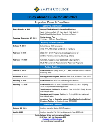
1INTRODUCTIONThis BALUSTRADE INSTALLATION GUIDE has beenrevised to be used with the LJ Line of stair parts. Beginning withthis introduction, Step 1, you will be guided through the stepsrequired for your particular stairway by a note at the bottom ofeach step indicating which step to go to next. This approachhas two benefits: first, you will be referred only to the steps youneed, and secondly, the sequence is designed with efficiency inmind and will help ensure that mistakes are not made by doingsomething out of sequence.An appendix for troubleshooting and unusual installations,Step 107, and a quick reference index, Step 108, round out theguide.Important: Before beginning your installation, take timeto thoroughly read all of the steps required for your stair. 2DNewels are the primary support of any balustradesystem and are recommended at the beginning,end, and at all changes of direction on a stairway.2EBalcony newels should be located no more than tenfeet (10') apart.2FConsult your local building codes prior to installation.2GAll stair parts are for interior use and installation only.GO TO 33BUILDING CODESGENERAL - It will be necessary to determine the followingcode requirements prior to beginning installation.GO TO 22GENERAL NOTESRAKE HANDRAIL HEIGHTThe minimum vertical distance from the tread nosingto the top of the handrail.IMPORTANT: Cut and fit all parts before permanentlyinstalling any of them. This will help reduce the chance oferror.2AThe LJ Line of Conect-A-Kit fittings are designed todecrease installation time. The time spent assemblingthe various components is outweighted by the time savedby avoiding the use of rail bolts.2BThe LJ Line of balusters and newels is designed toaccommodate virtually any building code requirement.2CIn order to provide a solid and durable installation, and toavoid squeaks, avoid the use of nails wherever possible.Use woodscrews, lag bolts, rail bolts and assembly glueon all joints.Page 3RakeHandrailHeightPage 4
BALCONY GUARDRAIL HEIGHTThe minimum vertical distance from the finished floor tothe top of the level railing.HANDRAIL CLEARANCEThe minimum clearance required between the handrailand any other object; such as a wall or landing treadnosing.BalconyGuardrailHeightGO TO 4BALUSTER SPACINGThe maximum spacing permitted between balusters.This will determine the number of balusters required foreach tread.4IS STAIR OVER THE POST ORPOST TO POST?POST TO POSTGO TO 6SphereSizeOVER THE POSTGO TO 5Page 5Page 6
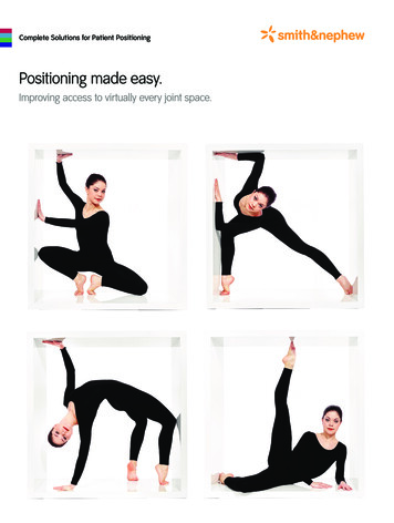
PLOW5OVER THE POSTDETERMINE THETYPE OFINSTALLATION OVER THE POSTLANDINGAThe illustrations below will help determine the type ofinstallation required.NO PLOWOVER THE POSTPLOWNO LANDINGNO PLOWBCDFor example, a type C stair is over the post, does not have anintermediate landing and uses plowed handrail.Remember the letter for your stair, as the "GO TO . . ." boxesat the end of each step may tell one letter to go on to the nextstep and tell another letter to skip one or more steps.Page 7A,B,C,D - GO TO 7Page 8
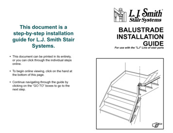
PLOW6POST TO POSTDETERMINE THETYPE OFINSTALLATION POST TO POSTKNEEWALLwith or without landingEThe illustrations below will help determine the type ofinstallation required.NO PLOWPOST TO POSTPLOWOPEN TREADwith or without landingNO PLOWFGHFor example, a type F stair is post to post, has a kneewalland uses unplowed handrail.Remember the letter for your stair, as the "GO TO . . ." boxesat the end of each step may tell one letter to go on to the nextstep and tell another letter to skip one or more steps.Page 9E,F,G,H - GO TO 7Page 10
7 MARK THE BALUSTRADE CENTERLINEAND NEWEL CENTERPOINTS1/2 KneewallWidthAn alternate method of locating the balustrade centerlinewhich does not require newel notching is described below.1/2 BalusterSquareALTERNATE VIEWLANDINGBALCONYLanding NewelCenterpointBalustradeCenterlineFRONT VIEWBalustradeCenterlineThe balustrade centerline and newel centerpoints caneasily be laid out using the L.J. Smith C-88 Centerline Tool.On a kneewall stair, the balustrade should be centered on thekneewall. On an open-tread stair, the centerline should be 1/2of the baluster square in from the face of the stringer; i.e.: 5/8"for a 1-1/4" baluster.LANDINGBalcony NewelCenterpointBalustradeCenterlineFace ofStringerStarting NewelCenterpointTOP VIEWThe newel centerpoints lie at the intersections of thebalustrade centerlines. Note that the above method typicallyrequires the notching of newels as described in step 107-A.Page 11BalustradeCenterlineFace of StringerStarting NewelBALCONYLanding NewelCenterpointUpBalcony NewelCenterpointOne method which does not require the notching of newelsis to mount the starting newel and intermediate landing neweldirectly against the riser. The balcony newel may be mountedflush to the floor with no overhang. Note that these methodsmay reduce the stair width and could pose problems interminating the balcony rail at a wall as well as effect the locationof the starting fitting template.A, B, C, D, G, H - GO TO 8E, F - GO TO 9Page 12
8MARK THE BALUSTER CENTERPOINTSFrom the baluster spacing required by code see step 3,determine the number of balusters required per tread. The firstbaluster of each tread should be 1/2 baluster square back fromthe face of the riser. Divide the run by the required number ofbalusters per tread to find the center-to-center distance for theother balusters. For example, if the run is 10" and the maximumspacing required by code is 4"; 10 divided by 4 equals 2-1/2spaces required per tread. Round this up to 3 spaces. Thus, 3balusters per tread are required. 10" run divided by 3 balustersequals 3.333" (3-11/32") center-to-center.Run1/2 Run1/2 Baluster SquareFace of RiserSecond BalusterFirst Baluster 9MARK THE BALUSTER CENTERPOINTSLanding NewelStartingNewelEqual Spacing C1/2 BalusterSquareHorizontal DistanceATotal HorizontalDistance BEQUAL SPACING CENTER-TO-CENTER (C):RunEquation 2Face of RiserSecond BalusterFirst BalusterA, B, C, D - ARE YOU USING AN OPENING CAP?YES - GO TO 11 / NO - GO TO 10G, H - GO TO 48 Equation 3(B) Total HorizontalDistanceSize of one BalusterSquareNumber of Spaces(Round up)Spacing Required byCode(B) Total HorizontalDistanceThird BalusterPage 13 (A) Horizontal Distance1/3 Run1/2 Baluster SquareWork through the following equations to determine theproper center-to-center baluster spacing. Use the end distance,obtained in Equation number 4, and the equal distance, obtainedin Equation number 3. Mark these points on the floor and doublecheck that they add up to the total horizontal distance. Use apumb-bob to plumb up from these points to mark the kneewall.Keep the spacing on different flights and on the balcony asconsistent as possible.Equation 11/2 Baluster SquareEnd Spacing D (C) Equal SpacingCenter-to-CenterNumber of Spaces(B) Total HorizontalDistanceEND SPACING (D) From face of Newel to Center of First Baluster):Equation 4-(C) Equal SpacingCenter-to-Center 1/2 Baluster SquareGO TO 48(D) End SpacingPage 14
10 TRACE THE STARTING FITTING TEMPLATE12TRIM THE STARTING EASINGTrim HereBalustradeCenterlineRiseRakeRunTemplateUsing the template provided with your starting fitting; alignthe balustrade centerline and mark the newel and balustercenterpoints on the starting tread.Trim the starting easing along the cut line using a miter saw.ARE YOU USING A CLIMBING VOLUTE?YES - GO TO 107-P / NO - GO TO 1111ARE YOU USING AN OPENING CAP?YES - GO TO 14 / NO - GO TO 1313MARK THE STARTING EASINGASSEMBLE THE STARTING FITTINGMark CutLineRiseRunMark TangentPointRunRiseAlways trim the end of the easing which has threepockets. Mark the tangent point on the easing with the "rise" legof the pitchblock lying flat. Mark the cut line on the easing withthe "run" leg of the pitchblock lying flat. Note: See Step 107-Efor instructions on how to make a pitchblock.Page 15GO TO 125/16" x 2" Lag BoltRemove the filler from the easing. Use a 5/16" x 2" lag boltand washer to assemble the single pocket end of the easing tothe volute or turnout. The LJ-3044 VersaTool may simplify thistask.GO TO 16Page 16
14 SQUARE CUT THE OPENING CAP16Mark and Trim HereASSEMBLE THE STARTING FITTINGTO THE HANDRAIL1 1/2" Deep5/16" x 3 1/2"Lag BoltThe mitered end of the opening cap must be square cut inorder to be assembled to the easing. Mark the opening cap atthe bottom edge of the miter. Square cut the opening cap at themark using a miter saw.Use the Rail Marking Template to mark the handrail. Drilla 1/4" x 1-1/2" deep pilot hole in the handrail. Assemble thestarting fitting to the handrail with a 5/16" x 3-1/2" lag bolt andwasher. The LJ-3044 VersaTool may simplify this task.GO TO 1515GO TO 17ASSEMBLE THE STARTING FITTING17CLAMP THE STARTING FITTING ANDHANDRAIL TO THE STAIRNutBalustrade Centerline5/16" x 2 1/4"Machine BoltCarefully remove the top lid of the opening cap using a puttyknife or chisel. Use a 5/16" x 2 1/4" machine bolt and nut toassemble the single pocket end of the easing to the openingcap. Use a 3/8" SAE washer on the bolt head end, and a 3/8"SAE washer with a 5/16" lock washer on the nut end. TheLJ-3044 VersaTool may simplify this task.Page 17GO TO 16Newel CenterpointClamp the assembly to the stair tread nosings using barclamps. Locate the handrail over the balustrade centerline andthe starting fitting directly over the starting newel centerpoint.GO TO 18Page 18
18MEASURE THE GAP UNDER THESTARTING FITTING 20SQUARE CUT THE INTERMEDIATELANDING FITTINGMark and Trim HereMeasure the verticaldistance from the treadto the underside of thestarting fitting. Writethis dimension downMeasurefor future use.the Gap19MEASURE THE RAKE HANDRAILTHICKNESSMeasurementMEASUREMENTA,B - GO TO 20 / C,D - GO TO 3321MARK THE EASING AT THE LOWER ENDOF THE SECOND FLIGHTMark TangentPointMark CutLineRiseMeasure the height of the handrail above the tread nosingwhile clamped to the treads or kneewall. Be sure the framingsquare is sitting on a tread and is lined up with the nosing. Writethis measurement down.Page 19GO TO 21GO TO 19RunMEASUREMENTThe mitered end of theintermediate landing fittingmust be square cut in orderto be assembled to the easing.Mark the intermediate landingfitting at the bottom edge ofthe miter. Square cut the fittingusing a miter saw. For fittingswith a cap, place a 5/8" spacerbetween the fitting and the mitersaw fence to help ensure asquare cut.RiseRunAlways trim the end of the easing which has threepockets. Mark the tangent point on the easing with the "rise" legof the pitchblock lying flat. Mark the cut line on the easing withthe "run" leg of the pitchblock lying flat. Note: See Step 107-Efor instructions on how to make a pitchblock.GO TO 22Page 20
22 TRIM THE EASING24ASSEMBLE THE INTERMEDIATELANDING FITTING TO THE SECONDFLIGHT HANDRAILTrim HereRise1 1/2"Rake5/16" 3-1/2"Lag BoltRunTrim the easing along the cut line using a miter saw.GO TO 2323Use the Rail Marking Template to mark the handrail. Drill a1/4" x 1-1/2" deep pilot hole in the handrail.Assemble the intermediate landing fitting to the handrailwith a 5/16" x 3-1/2" lag bolt and washer. The LJ-3044 VersaToolmay simplify this task.GO TO 25ASSEMBLE THE EASING TO THEINTERMEDIATE LANDING FITTINGNut25ASSEMBLE THE RAIL DROP TO THEINTERMEDIATE LANDING FITTING5/16" x 2"Lag Bolt5/16" x 2 1/4"Machine BoltUse a 5/16" x 2 1/4" machine bolt and nut to assemble thesingle pocket end of the easing to the intermediate landingfitting. Use a 3/8" SAE washer on the bolt head end, and a 3/8"SAE washer with a 5/16" lock washer on the nut end. TheLJ-3044 VersaTool may simplify this task.Page 21GO TO 24Assemble the rail drop to the intermediate landing fitting witha 5/16" x 2" lag bolt and washer.GO TO 26Page 22
26 CLAMP THE INTERMEDIATE LANDINGFITTING AND HANDRAIL TO THE STAIR28MARK THE EASING AT THE TOPOF THE FIRST FLIGHTMark TangentPointLanding NewelCenterpointRunRakeRiseClamp the assembly to the stair tread nosings using barclamps. Locate the handrail over the balustrade centerline andthe intermediate landing fitting directly over the landing newelcenterpoint.keRaRunBalustrade CenterlineRiseAlways trim the end of the easing which has threepockets. Stand the easing up on a level surface. Mark thetangent point on the easing with the "run" leg of the pitchblocklying flat. Mark the cut line on the easing with the "rise" leg ofthe pitchblock lying flat. Note: See step 107-E for instructionson how to make a pitchblock.GO TO 29GO TO 2727Mark Cut LineMEASURE THE GAP UNDER THEINTERMEDIATE LANDING FITTING29TRIM THE EASING AT THE TOPOF THE FIRST FLIGHTLanding Newel CenterpointLandingMeasurementTrim HereRiseRakeRunMeasure the vertical distance from the level of the landingto the underside of the intermediate landing fitting. Write thisdimension down for future use.Trim the easing along the cut line using a miter saw.MEASUREMENTPage 23GO TO 28GO TO 30Page 24
30 APPLY A PLYWOOD SEAT TO THE RAILDROP AND THE FIRST FLIGHT HANDRAIL32ASSEMBLE THE EASING TO THE RAILDROP AND THE FIRST FLIGHT HANDRAILRail Drop5/16" x 3 1/2"Lag BoltPlywood SeatsHandrailRail Drop5/16" x 2" Lag BoltHandrailTack-nail 4"-6" wide pieces of plywood to the underside of therail drop and to the handrail. This will be used as a temporaryseat for marking the rail drop and handrail for trimming.GO TO 3131EasingMARK AND TRIM THE RAIL DROP ANDTHE FIRST FLIGHT HANDRAILUse the Rail Marking Template to mark the rail drop and thehandrail. Drill a 1/4" x 1-1/2" deep pilot hole in the rail drop andthe handrail. Assemble the single pocket end of the easing tothe handrail with a 5/16" x 2" lag bolt and washer. Assemble thetri
guide for L.J. Smith Stair Systems. This document can be printed in its entirety, or you can click through the individual steps online. To begin online viewing, click on the hand at the bottom of this page. Continue navigating through the guide by clicking on the “GO TO” boxes to go to the next step. Page 3 Page 4 2D Newels are the primary support of any balustrade system and .