Transcription
THE COOPER UNIONALBERT NERKEN SCHOOL OF ENGINEERINGOFDM Modulation RecognitionUsing Convolutional Neural NetworksbyJustin AlexanderA thesis submitted in partial fulfillmentof the requirements for the degree ofMaster of EngineeringAdvised by: Dr. Sam Keene
THE COOPER UNION FOR THE ADVANCEMENT OF SCIENCE AND ARTALBERT NERKEN SCHOOL OF ENGINEERINGThis thesis was prepared under the direction of the Candidate’s Thesis Advisor and hasreceived approval. It was submitted to the Dean of the School of Engineering and the fullFaculty, and was approved as partial fulfillment of the requirements for the degree of Masterof Engineering.Dr. Richard J. Stock - Apr. 26 2017Dean, School of EngineeringDr. Sam M. Keene - Apr. 26 2017Candidate’s Thesis Advisor
AcknowledgementsFirst and foremost, I would like to thank my God, Lord Almighty, for giving me wisdom,strength, and courage to finish this project.I would also like to thank my family, especially my parents, for their support and encouragement. They pushed me to aim high, and that is why these pages are being written.I would also like to thank my thesis adviser Dr. Sam Keene for his constant guidance overthis project and my career life. Thank you for helping me succeed in both.I wouldn’t have made it through the data capture stage without the experience I gainedfrom working at MaXentric Technologies. Special thanks to Brian Woods for his help indebugging my code.Special thanks to Chris Curro for teaching me Neural Networks, and for being a great friend.i
ABSTRACTThe task of determining the relevant parameters of a transmission scheme is known as modulationclassification. Possible parameters of interest include carrier frequency, symbol time or modulationorder. In this thesis we focus on modulation format (linear vs OFDM) and modulation order. Thistask has applications in signal intelligence receivers (SIG INT), and cognitive radios. One possibleapplication is in military use, where friendly or non-friendly transmissions can be identified. Anotherpossible application is in a cognitive radio network, where knowledge of primary users transmissionscheme could be used as part of an underlay network scheme. A common approach for modulationclassification is support vector machines (SVM) with high order cumulants as features, however theproblem of classification of orthogonal frequency division multiplexing (OFDM) signals has notbeen fully explored. Furthermore, deep neural networks (DNN) have made tremendous advances inclassification problems, and there has been no prior work done on using live captured data to testmodulation classification using DNN. Therefore, four linear and OFDM modulations are capturedlive over a range of signal powers, and tested against with both SVM and DNN classifiers. The SVMclassifier with high order cumulant features achieved a classification rate of 99% for OFDMmodulations, but only achieved 93% accuracy for linear modulations. A convolutional neuralnetwork (CNN) achieved 99% classification for all 8 modulations. Additionally, the CNNgeneralizes better than the SVM classifier when trained over a range of SNR values. When trained inthis manner, the convolutional network significantly outperforms the SVM classifier when the SNRvalue is not known at the receiver.ii
Contents1 Introduction11.1Motivation for Research . . . . . . . . . . . . . . . . . . . . . . . . . . . .11.2Related Works . . . . . . . . . . . . . . . . . . . . . . . . . . . . . . . . .21.3Problem statement . . . . . . . . . . . . . . . . . . . . . . . . . . . . . . .32 Communication Basics2.12.25Digital Modulations . . . . . . . . . . . . . . . . . . . . . . . . . . . . . .62.1.1Linear Modulations . . . . . . . . . . . . . . . . . . . . . . . . . .62.1.2OFDM Modulations . . . . . . . . . . . . . . . . . . . . . . . . .9Signal Impairments . . . . . . . . . . . . . . . . . . . . . . . . . . . . . . 122.2.1Path Loss . . . . . . . . . . . . . . . . . . . . . . . . . . . . . . . 132.2.2Carrier Frequency Offset . . . . . . . . . . . . . . . . . . . . . . . 132.2.3Timing Offset . . . . . . . . . . . . . . . . . . . . . . . . . . . . . 15iii
2.2.4Multipath Fading . . . . . . . . . . . . . . . . . . . . . . . . . . . 153 Data Capture and Validation3.13.23.317ORBIT Testbed . . . . . . . . . . . . . . . . . . . . . . . . . . . . . . . . 173.1.1Software Defined Radios . . . . . . . . . . . . . . . . . . . . . . . 193.1.2GNU Radio . . . . . . . . . . . . . . . . . . . . . . . . . . . . . . 21Modulation Parameters . . . . . . . . . . . . . . . . . . . . . . . . . . . . 223.2.1Linear Modulations . . . . . . . . . . . . . . . . . . . . . . . . . . 233.2.2OFDM Modulations . . . . . . . . . . . . . . . . . . . . . . . . . 243.2.3Relative SNR . . . . . . . . . . . . . . . . . . . . . . . . . . . . . 27Validation . . . . . . . . . . . . . . . . . . . . . . . . . . . . . . . . . . . 283.3.1Constellation Diagrams . . . . . . . . . . . . . . . . . . . . . . . . 293.3.2Synchronization . . . . . . . . . . . . . . . . . . . . . . . . . . . . 324 Algorithms for Modulation Recognition374.1Support Vector Machines . . . . . . . . . . . . . . . . . . . . . . . . . . . 374.2Neural Networks . . . . . . . . . . . . . . . . . . . . . . . . . . . . . . . 394.2.1Multi Layer Perceptrons . . . . . . . . . . . . . . . . . . . . . . . 404.2.2Convolutional Neural Networks . . . . . . . . . . . . . . . . . . . 435 Modulation Classification5.146SVM . . . . . . . . . . . . . . . . . . . . . . . . . . . . . . . . . . . . . . 46iv
5.25.3NNet . . . . . . . . . . . . . . . . . . . . . . . . . . . . . . . . . . . . . . 575.2.1MLP Results . . . . . . . . . . . . . . . . . . . . . . . . . . . . . 585.2.2CNN Results . . . . . . . . . . . . . . . . . . . . . . . . . . . . . 61Comparison . . . . . . . . . . . . . . . . . . . . . . . . . . . . . . . . . . 706 Conclusion and Future Work73Appendices75A Relevant Source Code75A.1 MATLAB Code . . . . . . . . . . . . . . . . . . . . . . . . . . . . . . . . 75A.1.1 Linear modulation bit generator . . . . . . . . . . . . . . . . . . . 75A.1.2 OFDM frame sequence generator . . . . . . . . . . . . . . . . . . 75A.1.3 Linear modulation receiver . . . . . . . . . . . . . . . . . . . . . . 77A.1.4 OFDM modulation receiver . . . . . . . . . . . . . . . . . . . . . . 78A.1.5 Cumulant function . . . . . . . . . . . . . . . . . . . . . . . . . . 80A.1.6 Cumulant script for captured data . . . . . . . . . . . . . . . . . . 80A.1.7 SVM for single SNR data . . . . . . . . . . . . . . . . . . . . . . . 81A.1.8 SVM for multiple SNR data . . . . . . . . . . . . . . . . . . . . . 84A.2 GNU Radio Code . . . . . . . . . . . . . . . . . . . . . . . . . . . . . . . 87A.2.1 qam4 ic implementation in OOT module . . . . . . . . . . . . . . 87A.2.2 qam16 ic implementation in OOT module . . . . . . . . . . . . . . 89v
A.2.3 qam32 ic implementation in OOT module . . . . . . . . . . . . . . 92A.3 TensorFlow Code . . . . . . . . . . . . . . . . . . . . . . . . . . . . . . . 96A.3.1 Data capture segmentation . . . . . . . . . . . . . . . . . . . . . . 96A.3.2 MLP for single SNR data . . . . . . . . . . . . . . . . . . . . . . . 97A.3.3 CNN for single SNR data . . . . . . . . . . . . . . . . . . . . . . . 99A.3.4 CNN for multiple SNR data . . . . . . . . . . . . . . . . . . . . . 104Bibliography109vi
List of Figures2.1A simple communication system model. Figure taken from [11]. . . . . . . . .52.2Transmitter block diagram for linear modulations. . . . . . . . . . . . . . . . .72.3Symbol mapping for each of the 4 linear modulations. BPSK figure taken from[29]; QAM figures taken from [8]. . . . . . . . . . . . . . . . . . . . . . . . .82.4OFDM sub carriers. Figure taken from [20]. . . . . . . . . . . . . . . . . . . .92.5OFDM transmitter and receiver. Figure taken from [15]. . . . . . . . . . . . . . 102.6OFDM frame loading for 802.11a standard frames. Figure taken from 802.11astandard [7]. . . . . . . . . . . . . . . . . . . . . . . . . . . . . . . . . . . . . 122.7Effect of carrier frequency offset on QAM4 constellation. Figure taken from [30]. 142.8Signal degradation due to multiple copies of the signal arriving at the recevierwith delays. Illustration taken from [3]. . . . . . . . . . . . . . . . . . . . . . 163.1Schematic of USRP2 N210. Figure taken from USRP N210 manual [23]. . . . 20vii
List of Figures3.2BPSK transmitter code in GNU Radio Companion. . . . . . . . . . . . . . . . 213.3QAM4 transmitter code in GNU Radio companion . . . . . . . . . . . . . . . 233.4OFDM BPSK transmitter code in GNU Radio Companion. . . . . . . . . . . . 253.5OFDM frame sequence. . . . . . . . . . . . . . . . . . . . . . . . . . . . . . . 253.6Unsynchronized constellation diagrams for all the linear modulations. . . . . . 293.7Unsynchronized constellation diagrams for all the OFDM modulations. . . . . 313.8Synchronized constellation diagrams for all the linear modulations. . . . . . . . 333.9Synchronized constellation diagrams for all the OFDM modulations. . . . . . . 343.10 Synchronized constellation becomes tighter when TX gain is increased. . . . . 364.1Two classes shown in red and blue. Contours of constant y(x) are shown throughthe solid line. The decision boundary is between the support vectors which arecircled in green. Figure taken from page 331 of [1]. . . . . . . . . . . . . . . . 384.2Maximum margin between two classes and the optimal hyperplane in between.Figure taken from [17]. . . . . . . . . . . . . . . . . . . . . . . . . . . . . . . 394.33 layer MLP. . . . . . . . . . . . . . . . . . . . . . . . . . . . . . . . . . . . . 414.4Inside neuron h0 of figure 4.3. . . . . . . . . . . . . . . . . . . . . . . . . . . 414.5Simple convolutional neural network. Figure taken from [18]. . . . . . . . . . . 434.6Max Pooling example. Figure taken from [28] . . . . . . . . . . . . . . . . . . 44viii
List of Figures5.1Grid search example for finding optimal Cost and Gamma values. This SVMmodel is classifying between QAM16 and QAM32 modulations. A bigger gridsearch can provide a more optimal pairs of Cost and Gamma. . . . . . . . . . . 495.2Hierarchical Model for SVM classification for all modulations. . . . . . . . . . 505.3Kfold validation results for SVM # 1. This SVM classified between linear andOFDM modulations. . . . . . . . . . . . . . . . . . . . . . . . . . . . . . . . 505.4Kfold validation results for linear modulations (SVM # 2). . . . . . . . . . . . 515.5Kfold validation results for OFDM modulations (SVM # 3). . . . . . . . . . . 525.6Decision boundaries for the classes in linear and OFDM modulations. Theclassifier is taken from one of the ten models in the Kfold validation test. . . . . 545.7Kfold validation results for all modulations together. . . . . . . . . . . . . . . 555.8Kfold results for linear modulations when SVM is fed with data from all TXgain levels. . . . . . . . . . . . . . . . . . . . . . . . . . . . . . . . . . . . . 565.9Kfold results for OFDM modulations when SVM fed with data from all TXgain levels. . . . . . . . . . . . . . . . . . . . . . . . . . . . . . . . . . . . . 565.10 Kfold results when SVM is fed with data from all modulations and TX gain levels. 575.11 Multi Layer Perceptrion Model . . . . . . . . . . . . . . . . . . . . . . . . . . 585.12 MLP model results with Ninput 1024, Nf c1 512, Nout 2. This model wasattempting to classify between BPSK and QAM4 modulated signals. . . . . . . 605.13 1024 I samples from BPSK and QAM4 modulations. . . . . . . . . . . . . . . 61ix
List of Figures5.14 Conv Net Model Template . . . . . . . . . . . . . . . . . . . . . . . . . . . . 625.15 Training and validation cross entropy loss function for OFDM modulationclassification with Model # 1. . . . . . . . . . . . . . . . . . . . . . . . . . . . 645.16 Training and Validation accuracy for OFDM modulation classification withModel # 1. . . . . . . . . . . . . . . . . . . . . . . . . . . . . . . . . . . . . . 655.17 Activations functions. . . . . . . . . . . . . . . . . . . . . . . . . . . . . . . . 665.18 CNN performance with each SNR data. NNet Model # 1 (M1) is on the left;NNet Model #2 (M2) is on the right. These models are trained for 5 epoch withbatch size of 50. Roughly 16K examples per class used for training, and roughly2K examples per class where used as test set. . . . . . . . . . . . . . . . . . . 675.19 CNN confusion matrix from model # 2 for a) linear, b) OFDM and c) Allmodulation cases with the specified parameters. These are the poor performancecases in their respective categories. . . . . . . . . . . . . . . . . . . . . . . . . 685.20 CNN performance of both models when trained with examples from all TX gainlevel. These models were trained for 10 epoch with batch size of 100. Roughly16K examples per class and TX gain level were used for training. Tested againstroughly 2K examples per class and TX gain level. . . . . . . . . . . . . . . . . 695.21 Training and validation accuracy values for CNN Models. . . . . . . . . . . . . 69x
List of Figures5.22 CNN confusion matrix of model # 2 with all TX gain data for a) OFDM worseperformance case, and b) All modulations best performance case with thespecified parameters. . . . . . . . . . . . . . . . . . . . . . . . . . . . . . . . 705.23 Performance of SVM and CNN at different TX gain level, and with all TX gainlevel. . . . . . . . . . . . . . . . . . . . . . . . . . . . . . . . . . . . . . . . . 71xi
NomenclatureAdam Adaptive Moment EstimationBER Bit Error RateBNBatch NormalizationCN N Convolutional Neural NetworkCRCognitive RadioDN N Deep Neural NetworkF DE Frequency Domain EqualizerF SK Frequency Shift KeyingGDGradient DescentGRC GNU Radio Companionxii
NomenclatureHOC Higher Order CumulantsISIInter Symbol InterferenceM LP Multi Layer PerceptronsN N et Neural NetworkOOT Out Of TreeORBIT Open-Access Research Testbed for Next-Generation Wireless NetworksP CA Principal Component AnalysisP RT Pattern Recognition ToolboxQAM Quadrature Amplitude ModulationRBF Radial Basis FunctionReLU Rectifier Linear UnitRRC Root Raised CosineRXReceiverSDR Software Defined RadiosSN R Signal to Noise Ratioxiii
NomenclatureSV M Support Vector MachineTXTransmitterU HD USRP Hardware DriverU SRP Universal Software Radio Peripherals*xiv
1Introduction1.1Motivation for ResearchThere are many uses for modulation recognition algorithms; one of its primary uses arein a signal intelligence (SIG INT) receivers. A SIG INT receiver’s job is to monitor andintercept foreign communication signals, and gain information regarding the message beingtransmitted. To do such task, a SIG INT receiver needs to know what type of modulationhas been applied on the transmitted signal. This is where a robust modulation recognitionalgorithm, which is able to classify among various modulation type, comes in useful.Modulation algorithms can also be used in cognitive radios (CR). CR are programmedfor efficient utilization of the frequency spectrum for transmission which is being sharedamong multiple users [2]. This is typically done by detecting and transmitting when thechannel is unoccupied. A modulation recognition algorithm can be used here to detect1
CHAPTER 1. INTRODUCTIONif a channel is in use. CR can perform more intelligently in an underlay network if theunderlying modulations of the primary users is also known.There has been much research into modulation recognition algorithms for many different modulation classes. This thesis will be expanding upon the research by applying neuralnetworks (NNet) to modulation classification. Many experimenters have already done this,but with synthesized data. Current state of the art classifiers are support vector machine(SVM) with high order cumulants (HOC) as its features. Neural networks are a more recenttype of classification algorithm, and their effectiveness on classifying modulation schemeshas not yet fully been explored.1.2Related WorksThere has been some prior work into classifying OFDM modulations. In [12] the authorsdesign a system for OFDM signal classification. In their model a gaussianity test is done todistinguish between OFDM and single carrier modulations. Furthermore, their system thenestimates the relevant parameters of the OFDM modulations, such as the OFDM symbolrate, cyclic prefix interval, and number of sub carriers. They have noted that their systemis able to classify between OFDM and non OFDM signal with 80% accuracy, and theirparameter extraction accuracy is greater than 90% for SNR above 15 dB.In [26], the authors apply convolutional neural nets (CNN) to classify several lin2
CHAPTER 1. INTRODUCTIONear modulations. Digital modulations that were classified includes BPSK, QPSK, 8PSK,16QAM, 64QAM, BFSK, CPFSK, and PAM4. They also included 3 analog modulations:WB-FM, AM-SSB, and AM-DSB. Their dataset was synthesized in GNU Radio using harshchannel models. Their CNN was trained with SNR data ranging from -20dB to 20dB.Their overall accuracy across all the SNR levels was roughly around 87%.1.3Problem statementIn this thesis, four linear modulations will be classified: BPSK, QAM4, QAM16, andQAM32, along with 4 OFDM based modulation: OFDM-BPSK, OFDM-QAM4, OFDMQAM16, and OFDM-QAM32. Two different classifiers will be trained and tested for theirperformance in classifying these modulations. The classic SVM classifier with cumulantfeatures are considered state of the art for the modulation classification. Neural Networkshave recently become popular for their ability to learn features from complex data sets.To the author’s knowledge neither of these classifier have been tested to classify OFDMmodulations with live captured data. Therefore, these two classifiers will be trained andtested with live captured data sets. They will be tested for their ability to simultaneouslyclassify both linear and OFDM modulations across several SNR levels.This thesis is organized as follows. In chapter 2, a brief explanation of digital modulations will be given. Chapter 3 will describe how the data was captured and validated.3
CHAPTER 1. INTRODUCTIONChapter 4 explains the classifiers that will be used, and in Chapter 5 the results will bepresented. In Chapter 6 we conclude and list the future works for interested readers.4
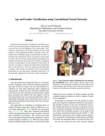
2Communication BasicsThis chapter is presented to give a brief overview on modulation’s waveform design parameters and the types of impairment that can be seen on a signal transmitted over the air. Atypical communication system model can be seen in the figure 2.1.Figure 2.1: A simple communication system model. Figure taken from [11].Information Source is the message being transmitted; these are usually in the form ofa binary bit stream. Transmitter modulates the bit stream into the carrier frequency andtransmits it into the air. The signal goes through a channel, which adds impairment to thesignal. If the receiver is not synchronized with the transmitter then additional impairments5
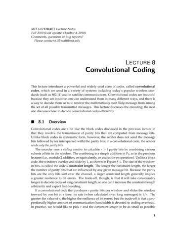
CHAPTER 2. COMMUNICATION BASICSwill be seen at the receiver. Both of these subjects, modulations and impairments, will bediscussed in the next two sections.2.1Digital ModulationsAs mentioned previously, 8 different type of digital modulation signals are classified in thisresearch. They can be categorized as linear and OFDM modulations. OFDM modulatedschemes are relatively new compared to linear modulation schemes like QAM, and they areboth used widely today.2.1.1Linear ModulationsResearchers have come up with wide variety of digital modulations for data transmission.Most common of them all are Frequency Shift Keying (FSK) and Quadrature AmplitudeModulations (QAM). These modulations are simple to implement in a transmitter, andsimple enough to build a receiver for. Figure 2.2 shows a typical transmitter for the 4modulations of interest.The bit streams are fed in from top level API (Host), which is mapped into complexsymbols by the modulator. Those symbols are then up sampled with repetition or digitallyinterpolated to the sampling rate required for the transmission. Then, the complex stream ismultiplied by the local oscillator (LO), which up converts the signal to radio frequency (RF).6
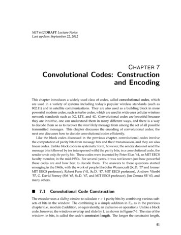
CHAPTER 2. COMMUNICATION BASICSFigure 2.2: Transmitter block diagram for linear modulations.This is the model that has been used to transmit linear modulations for this research. Pulseshaping can be applied to the signal to reduce inter symbol interference (ISI), however thatis not common in modern transmitters. For this project pulse shaping is not applied, and arectangular pulse shape is assumed for all modulations.Equation 2.1 shows the output values of the transmitted signal:s(t) I(t)cos(2πf0 t) Q(t)sin(2πf0 t)(2.1)where I(t) and Q(t) are the complex baseband symbols in the time domain. I standsfor in-phase, and Q stands for quadrature phase. The digital modulator maps the bits ontosymbol. It is easier to visualize the mapping by viewing it in a constellation diagram. Theconstellation diagram for the 4 linear modulations are shown in figure 2.3. The symbols aremapped based on the bit order seen on top of them.7
CHAPTER 2. COMMUNICATION BASICS(a) BPSK(b) QAM4(c) QAM16(d) QAM32Figure 2.3: Symbol mapping for each of the 4 linear modulations. BPSK figure taken from[29]; QAM figures taken from [8].Higher order QAM packs more bits per symbol, hence they have higher spectralefficiency compared to lower order QAM. One drawback is that the receiver has to be morecomplex for higher order QAMs. It is easy to track the frequency offset for BPSK or QAM4modulations, but requires power detection circuitry for higher level QAMs. Consequentlyhigher order QAMs tends to have higher bit error rate (BER).8
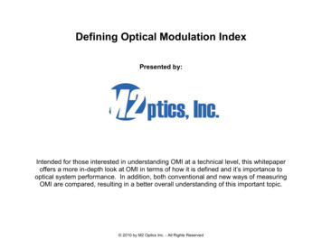
CHAPTER 2. COMMUNICATION BASICS2.1.2OFDM ModulationsOrthogonal Frequency Division Multiplexed (OFDM) modulations are multi carrier modulations. These modulations are considered as wide band signals, because their bandwidthis significantly larger compared to linear modulations due to having multiple carriers. Themain benefit of having multiple carrier system is that that it is robust against severe channelconditions such as multipath fading [5]. Another benefit is the ability to use frequencydomain equalizer (FDE) to compensate for channel impairments. FDEs are simple toimplement, and can be learned fairly quickly with the use of training frames.Figure 2.4: OFDM sub carriers. Figure taken from [20].OFDM modulations are considered orthogonal because at the optimum sampling pointthe contribution from adjacent carriers is exactly zero as seen in figure 2.4. This alignment,however, is easily broken if there is a frequency offset, which is why the receiver needscomplex algorithms to ensure frequency synchronization.9
CHAPTER 2. COMMUNICATION BASICS f SamplingRate/Ncarriers(2.2)There are many ways to implement an OFDM system; the most popular way of doingit is by using the FFT operation. This method is also used in 802.11a wireless standard [7].The block diagram of an OFDM system using this method is shown in figure 2.5.Figure 2.5: OFDM transmitter and receiver. Figure taken from [15].The input bit stream is mapped into symbols by the Constellation Mapper block on aframe by frame basis. The complex symbols are then loaded into an IFFT block to get atime domain representation of the input signal. Cyclic prefix addition operation is performedby copying the last Ncp samples into the front of the frame. The frames are then serialized10
CHAPTER 2. COMMUNICATION BASICSby a Parallel to Serial block and transmitted. At the receiver, the reverse operation is done,with the addition of a Frequency Domain Equalizer block, which is needed to remove ISI.OFDM signals are made up of frames. The frame size is determined by the length ofFFT and cyclic prefix. For example, in the 802.11a standard, the FFT size is 64, and the CPsize is 16. So there are 80 samples per OFDM frame [7]. There are different types of framethat are sent periodically. For our purposes there are only three different kinds of frames:preamble, training, and data frames. Both the preamble and the training frames are known atthe receiver, which is utilized for synchronization. The receiver uses the preamble frame todetect frame boundaries. The training frames are used to learn the FDE coefficients. Oncethe equalizer weights are learned, it is possible to extract the transmitted symbols from thedata frame.Each FFT bin can be thought of as a separate carrier frequency. In this particularOFDM system there are 64 carriers. Typically some of the carriers are nulled to taper thefrequency spectrum around the edges. Data frames, in 802.11a standard, are transmittedusing the loading pattern shown in figure 2.6There are 4 pilot carriers, # 7,21,-21, and -7, that are used in the standard. The receiverknows the values of the pilot symbols in advance, so these can be used to measure frequencyoffset, and also to fix timing offset. The rest of the carriers are loaded with data symbols,which are mapped by the appropriate modulator. Thus, out of 64 carriers, 48 are data carriers,11
CHAPTER 2. COMMUNICATION BASICSFigure 2.6: OFDM frame loading for 802.11a standard frames. Figure taken from 802.11astandard [7].4 are pilot carriers, and 12 are null carriers.The values of preamble frames are also taken from the 802.11a standard [7]. Thetraining frame is a custom frame that was created to train the FDE. It is loaded the same waya data frame would be loaded, except the data sequence are BPSK symbols with alternatingbits. The symbols going into consecutive data carriers are 1, -1, 1, -1 . Data symbolsfrom the training frame are used to compute the FDE coefficients.2.2Signal ImpairmentsThere are a couple of signal impairments that are expected to be seen at the receiver. Theeffects are different for narrow band and wide band signals. They are listed in the followingsections.12
CHAPTER 2. COMMUNICATION BASICS2.2.1Path LossThe biggest noticeable impairment to be seen is the severe attenuation of the transmittedsignal while it travels over the air. This happens because signal loses its power as it coversdistance. The free space path loss is shown in equation 2.3, in which we see that the signalloss in power is proportional to square of the distance traveled. Path loss is the biggest factorin signal to noise ratio (SNR) degradation for over the air transmitted signal. In the setupused for data capturing, the distance between the transmitter and receiver is not known,however they are close enough to properly transmit and receive data. The setup will beexplained in detail in the next chapter.F SP L (4πd/λ)22.2.2(2.3)Carrier Frequency OffsetTypically the effect of this impairments can be seen in constellation diagram, especially forthe linear modulations. Carrier frequency offset impairment occurs due to the mismatchbetween local oscillator of the transmitter and receiver, and also if either of those two aremobile. This makes the constellation of a particular modulation to rotate. Figure 2.7 showsan example of constellation rotation for QAM4 modulation.There are many effective algorithms designed to mitigate this type of impairment, mostnotable of them all is the costas loop that can be applied on BPSK and QAM4 modulated13
CHAPTER 2. COMMUNICATION BASICSFigure 2.7: Effect of carrier frequency offset on QAM4 constellation. Figure taken from[30].signals [25]. Variants of this algorithm are applied for higher order QAM modulations, butthey are more complex.This impairment has more profound effect on OFDM modulations because it breaks theorthogonality of the carriers. The carrier starts leaking into adjacent carriers which degradesthe SNR. This impairment is termed as Inter-carrier interference (ICI). Many pilots basedtechniques can be implemented to detect and mitigate this particular impairment for OFDMsignals [9] [13].14
CHAPTER 2. COMMUNICATION BASICS2.2.3Timing OffsetThis has different meaning for linear and OFDM modulations. In linear modulations, thisimpairment is seen when there is an offset in the clock frequency of the transmitter andreceiver. TX clock frequency determines the optimal sampling time of the signal, and if RXhas a different sampling time then the SNR is reduced. This impairment causes a shifting inthe optimal sampling point. Algorithms like early-late gate were designed to keep track ofthe optimal sampling point at the receiver. Digital communications book by Michael Ricehas a dedicated chapter on timing synchronization and covers early-late gate algorithm [24].In OFDM modulations, timing offset refers to the offset between what receiver considers to be the frame boundary and the actual frame boundaries. It is important to knowwhere the frames are starting, otherwise the demapping of known symbols from pilot andtraining will be incorrect. Typically, a correlator type algorithm can be used to match theframe boundaries [14].2.2.4Multipath FadingAnother distortion that is seen, especially in a wide band signal, is multipath fading. Thisarises due to multiple copies of the transmitted signal arriving at the receiver, with differentdelays. See figure 2.8 for an illustration. Some of the copies can combine destructivelywith the main dominant signal degrading the SNR. This problem is seen mostly in an urban15
CHAPTER 2. COMMUNICATION BASICSenvironments where the signal paths are longer creating a relatively large delay profile.Figure 2.8: Signal degradation due to multiple copies of the signal arriving at the recevierwith delays. Illustration taken from [3].Fading creates dips in the frequency spectrum, which degrades the signal quality. Thesetup in which all the data has been captured is an indoor environment. Therefore the delayprofile associated with that environment is small. This means that the fading shouldn’t be toosevere for narrow band signal. Wide band signal like OFDM modulations may experiencefading. It is possible that one of
been fully explored. Furthermore, deep neural networks (DNN) have made tremendous advances in classification problems, and there has been no prior work done on using live captured data to test modulation classification using DNN. Therefore, four linear and OFDM modulations are captured