Transcription
Procedia Computer ScienceProcediaProcedia ComputerComputer ScienceScience 101101,, 20162016,, PagesPages 292291 –– 299298YSCYSC 2016.2016. 5th5th InternationalInternationalYoungYoung ScientistScientist ConferenceConference onon ComputationalComputational Science,ScienceNumerical Modeling of Freeform RefractiveSurfaces Forming Line Radiation PatternYana Mazur and Anna VoznesenskayaITMO University, Saint Petersburg, Russiajanamazur27@gmail.com, voznesenskaya@mail.ifmo.ruAbstractThe original purpose of the study is to solve the inverse problem of synthesis of freeform opticalelements. This article describes a numerical approach for synthesis of freeform refracting surfacesforming a line radiation pattern.Keywords: illumination optics, freeforms, computer modeling, radiation pattern1. IntroductionNon-imaging optics arose around the 16th century, when was invented compound parabolicconcentrator (CPC) and has been evolved all the time. The objective for non-imaging devices isthe efficient transfer of light power between a source and a receiver, without image forming. Nonimaging systems are usually simple, consisted of several surfaces (freeforms) and do not respondto production errors. This makes the non-imaging optics a main tool in the designs forphotovoltaic concentration, illumination, and wireless optical communication, and others. Anotherfield of application of non-imaging optics is illumination system design, where the aim is toachieve the specific illumination distribution; for example, automotive headlamps design. In thiscase intensity distribution is defined by standards (ECE en European Union, and SAE in UnitedStates of America). There are several ways to create non-imaging optics: Flowline method,Poisson bracket method and Simultaneous Multiple Surface method (SMS), and others [1-9]. SMSmethod is the most powerful tool of all mentioned ones and it provides to develop simultaneouslyvarious surfaces. It was developed for design in two dimensions (2D), while the 3D surfaces wereobtained by rotational or lineal symmetry. Later it was extended to three dimensions (SMS 3D), sothat surfaces without symmetry (freeform) could be designed. SMS 3D method generates at leasttwo freeform surfaces at the same time (refractive or reflective). It gives full control over imagewidth and rotation, produces minimum vertical spread and can control the vertical image size, norotation, and optimizes pattern esthetics [10-16].Meantime a set of applications exists when there is a need to design a freeform elementforming a special exit light distribution (radiation pattern), e.g. a line or a curve. In this case theSMS method is not convenient to use. It is required a special calculations for the freeform surfacesynthesis. The refractive surface can be represented as ellipsoids of rotation or envelopehyperboloids which depend on the refractive indices of the media shared surface. The specifiedfreeform surface allows to convert a spherical beam of light from a source to a collimated beam ofa predetermined direction [15-19]. A number of papers of L.L. Doskolovich et al are devoted to292doi:10.1016/j.procs.2016.11.034Peer-review under responsibility of organizing committee of the scientific committee of the5th International Young Scientist Conference on Computational Science 2016 The Authors. Published by Elsevier B.V.
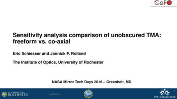
Numerical Modeling of Freeform Refractive Surfaces Forming Line Radiation PatternYana Mazur and Anna Voznesenskayasolution of this inverse problem and findings of accurate mathematical descriptions of the lightredistribution [20-23].In the given paper there is a continuation of these investigations in a part of a numerical modeldevelopment and further computer model realization.2. Method of a Refractive Surface SynthesisIllumination optics task concludes in synthesis of a refracting (reflecting) freeform surface forthe given parameters of the radiation source and exit radiation pattern. In this paper a pointradiation source is considered. The radiation pattern is a plot to the directional (angular)dependence of brightness or light intensity and has a shape of a line, arc, and others. Based on themathematical model, which is proposed in the paper of A.Yu. Dmitriev [22], a freeform surfacemay be generated.Illuminating light beam with a plane wavefront enters on a refractive optical element. Arefractive index is n1 for the element and n2 for the environment. The first surface of the element isflat and located in a plane z 0. The other surface is described by a function z z(x,y). Refraction ofrays occurs on the second surface of the optical element. Thus the task is the computation of therefractive surface shape z(x,y) [21-23] (Figure 1).Figure 1: Synthesis of freeform optical surfacesRadiation pattern is described with the unit vector: ሺߪሻ ൌ ቀ ௫ ሺߪሻǡ ௬ ሺߪሻǡ ௭ ሺߪሻቁ ǡ ȁ ሺ ሻȁ ൌ ͳ,(1)where ɐ א ሾͲǡ ሿ – some parameter. For example, it may be in the form of arcs, combination oftwo arcs, or more (Figure 2). The equation of the envelope surface z(x,y) can be obtained in ananalytical form. It is in general: ݖ ሺߪǡ ݕ ሻ ൌଵଵି మభ ሺఙሻή ሺ߰ሺߪሻ ݊ଶଵ ௫ ሺߪሻ ሺఙሻା௬ఛೣ ሺఙሻఛ ሺఙሻ ݊ଶଵ ௬ ሺߪሻ ݕ ሻ(2)When ௫ ሺߪሻ ൌ Ͳ in a radiation pattern, refractive surface corresponds to the cylindricalsurface: ݖ ሺߪǡ ݕ ሻ ൌଵଵି మభ ሺఙሻή ൫߰ሺߪሻ ݊ଶଵ ௫ ሺߪሻ݈ሺߪሻ൯ (3) 293
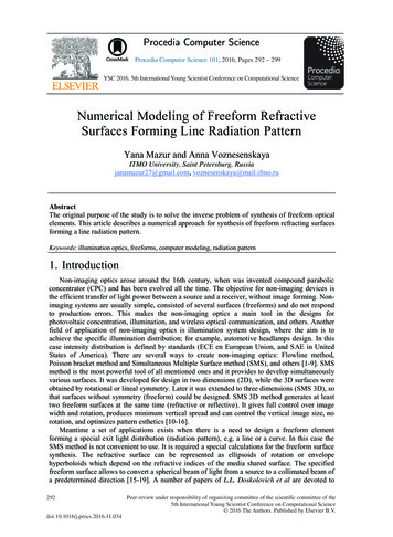
Numerical Modeling of Freeform Refractive Surfaces Forming Line Radiation PatternYana Mazur and Anna Voznesenskaya500y220 603 2u103 1u1031u10032u10x600400200y10y2 200 400 6003 2u103 1u10331u1002u10x1 x2abFigure 2: Radiation patterns (examples): (a) – arc; (b) – two arcsDirection vectors of two intersecting lines (intersecting lines form the envelope surface) are: ሺߪሻ ൌ ሺߪሻ ൈడ ሺ ሻడఙ,(4)where ሺߪሻ ൌ ሺ ௫ ሺߪሻǡ ௬ ሺߪሻǡ ௭ ሺߪሻ െଵ మభሻ - normal vector.In general case, ݐ ௭ ሺߪሻ ് Ͳ and a straight line with the direction vector (4) crosses the planez 0. ߬ሺߪሻ is the unit projection of the vector ሺߪሻ to (4) on the plane z 0.ଶௗ ௗߪሺ݈ሻ ൌ ቆ ିଵ ቀ ቁ ටͳ െ ቀ ቁ ቇ ǡ గோோோ ଶ (5) where σ is substituted into the equation (5) and then we can find l.The function ߰ሺߪሻ determines the distribution of energy along the radiation pattern:డటሺఙሻడఙൌ ۓ ۖ ଵೣ ሺఙሻఛೣ ሺఙሻା ሺఙሻఛ ሺఙሻ ۔ ۖ ە െ݊ଶଵ ሺ݈ሺߪሻ ቀ൭ ݊ଶଵ ݐ ௭ ሺߪሻ݈ሺߪሻ ߰ሺߪሻ ቆడ ೣ ሺఙሻడఙ ݊ଶଵడ ሺఙሻడఙడ ೣ ሺఙሻడఙ ೣ ሺఙሻቁଵି మభ ሺఙሻ߬௫ ሺߪሻ డ ሺఙሻడఙటሺఙሻడ ሺఙሻଵି మభ ሺఙሻడఙThe equation (6) can be solved with Bernoulli differential equation.294߬௬ ሺߪሻቇ൱ ǡ ݐ ௭ ሺߪሻ ് Ͳǡ ݐ ௭ ሺߪሻ ൌ Ͳ(6)
Numerical Modeling of Freeform Refractive Surfaces Forming Line Radiation Pattern మభ ௧ ሺఙሻ ሺఙሻܳሺߪሻ ൌଵܲሺߪሻ ൌ െNext: ೣ ሺఙሻఛೣ ሺఙሻା ሺఙሻఛ ሺఙሻ൬ డ ೣ ሺఙሻడఙYana Mazur and Anna Voznesenskaya߬௫ ሺߪሻ డ ሺఙሻడఙ߬௬ ሺߪሻ൰and. ೣ ሺఙሻఛೣ ሺఙሻା ሺఙሻఛ ሺఙሻLet us consider inhomogeneous linear differential equation of the first order: ߰ሺߪሻᇱ ܲሺߪሻ߰ሺߪሻ ൌ ܳሺߪሻ. We seek a solution of the original equation in the form of a product of twofunctions: ߰ሺߪሻ ൌ ݑ ή ݒ , where u, v – functions of ߪ. Differentiate: ߰ሺߪሻᇱ ൌ ݑ ᇱ ή ݒ ݑ ή ݒ Ԣ.Substitute into the original equation: ݑ ᇱ ή ݒ ݑ ή ݒ ᇱ ܲሺߪሻ ݒݑ ൌ ܳሺߪሻ. Takeaway u outside thebrackets: ݑ ᇱ ή ݒ ݑ ή ሺ ݒ ᇱ ܲሺߪሻ ݒ ሻ ൌ ܳሺߪሻ. As v we take any, non-zero, solution of the equation:ௗ௩ ܲሺߪሻ݀ߪ ൌ Ͳ. ݒ ᇱ ܲሺߪሻ ݒ ൌ Ͳ. We multiply both sides by dx and divide by v:௩Integrate:ௗ௩ ܲ ሺߪሻ ݀ߪ ൌ ܥ . The constant C is zero, because we need any nonzero solution. ௩ௗ௩௩ൌ ȁ ݒ ȁ ൌ െ ܲ ሺߪሻ ݀ߪ Then we potentiating and drop the module sign (sign moduleௗ௨reduces to multiplication by a constant 1): ݒ ൌ ݁ ି ሺఙሻ ௗఙ . Thenceௗఙൌ ܳሺߪሻ݁ ሺఙሻ ௗఙ . Andintegrate: ݑ ൌ ܳ ሺߪሻ݁ ሺఙሻ ௗఙ ݀ߪ ܥ .Finally, we find: ݕ ൌ ݑ ή ݒ ൌ ൣ ܳ ሺߪሻ݁ ሺఙሻ ௗఙ ݀ߪ ܥ ൧ ή ݁ ି ሺఙሻ ௗఙ .As a result, when all known variables are substituted, we receive multiple coordinates of pointsbelonging to the freeform surface. For example, it is a special case where the radiation pattern is aline (7): ݖ ሺߪሻ ൌቆଵଵି మభ ήమඨቀ ష ቁ శೌమమିଶ ήሺௗିଶఙሻௗ మ ିସௗήఙାସሺ మ ାఙమሻ ή మభήሺೌమටቀఙି ቁ ା మమଵή ቆെ݊ଶଵ ή ݈ሺߪሻ ή ൬ మଵିቀఙି ቁଶቆቀఙି ቁ ା మ ቇቇ൱ ൮݊ଶଵ ଶ ή ݈ሺߪሻ ή ή ቌమ ష ቁమೌ୲ୟ୬ቀଶఙିௗଵ൰ቇ ൭݊ଶଵ ଶ ή ݈ሺߪሻ ή ήඥௗ మ ିସௗήఙାସሺ మ ାఙ మ ሻ మమ ଶଵమ ష ቁమೌ୲ୟ୬ቀቍ൲ ݊ଶଵ ή ݈ሺߪሻ ή ఙି మమටቀఙି ቁ ା మమሻ(7)3. The Resulting Refractive SurfaceIn this paper we consider the calculation of refractive optical elements on an example, whenthe radiation pattern is a line (Figure 3). It has certain coordinates which are located in a remoteௗplane z a (a - is position of the surface along the axis z): ሺߪሻ ൌ ቄߪ ǡ Ͳǡ ܽቅ ǡ ߪ߳ሾͲǡ ݀ሿ (d – is ሺ ሻଶlength of radiation pattern), ሺ ሻ ൌ ȁ ሺ ሻȁ.In our case ߪ߳ሾͲǡ ͲͲͲሿ, we substitute this into equation (5), and find l. This equation can besolved analytically only if it is received with a numerical method, using appropriate theoreticalfoundations and logic. We find on the interval [-R, R] an approximate solution (5) with a certainstep, e.g., 1. We use the method of Runge-Kutta, which is a fourth-order method. We define theinitial condition - the solution at the start point ߪ ൌ Ͳ. Using the special function "rkfixed" inMathcad, we get a set of points that is the solution of the equation (5). Figure 4 depicts a plot ofl(σ), which is a solution of (5) with our values.Since ௬ ሺߪሻ ൌ Ͳ, that ݐ ௭ ሺߪሻ ൌ Ͳ and use the second equation of (6). In the particular case, theradiation pattern in the form of a segment forms a cylindrical refracting surface [3].295
Numerical Modeling of Freeform Refractive Surfaces Forming Line Radiation PatternFigure 3: The radiation pattern is a lineYana Mazur and Anna VoznesenskayaFigure 4: Graphical solution of the equation (5)(for σ (0, 3000 mm), R 20 mm, d 3000 mm)The computer model was realized using Mathcad software. The modeling result is a set ofpoints on the refractive surface. If we approximate them, then we get the corresponding surfaceprofile (Figure 5). In the Figure 6 is shown a sectional refractive surface, which is obtained in apractical way and using a mathematical algorithm in Mathcad. The input data for the algorithm isthe length of the radiation pattern, the position of the surface along the axis, and the radius of theangular size of the arcs of the radiation pattern (if any), the refractive index of the optical elementand the environment and the type of source.For freeform surface modeling we need to create an algorithm S that calculates the coordinatesof all future points of the surface:ܵൌ296݈ א െܴ ǥ ܴ ۓ ௗ ଶௗۖߪሺ݈ሻ ՚ ቆ ିଵ ቀ ቁ ටͳ െ ቀ ቁ ቇ గோோோଶۖۖଵ ή మభଶఙିௗήሺή ቆെ݊ଶଵ ή ݈ሺߪሻ ή ൬ మ൰ቇ ೌۖ ݖ ሺߪሻ ՚ ଵି మభήඥௗ ିସௗήఙାସሺ మ ାఙ మ ሻ మమටቀఙି మ ቁ ା మۖඨቀ ష ቁ శೌమమ ۔ ଵିଶ ήሺௗିଶఙሻଵ ൭݊ଶଵ ଶ ή ݈ሺߪሻ ή ή ቆ మ ۖమ ష ቇ൱ ଶௗ ିସௗήఙାସሺ మ ାఙ మ ሻ୲ୟ୬ቀቁమೌۖۖ ିቀఙି ቁఙିଵଵۖమమ ൮݊ଶଵ ଶ ή ݈ሺߪሻ ή ή ቌ ቍ൲ ݊ή݈ሺߪሻήሻଶଵమమ ష మ ଶۖ୲ୟ୬ቀቁටቀఙି ቁ ା మቆቀఙି ቁ ା మ ቇమೌమమ ە (8)
Numerical Modeling of Freeform Refractive Surfaces Forming Line Radiation PatternaYana Mazur and Anna VoznesenskayabFigure 5: The three-dimensional graph of the resulting refractive surface (cylinder) for a lineradiation pattern: (a) d 3000 mm; (b) d 1500 mmabFigure 6: Optical freeform surface in a cut (the dependence of the function z(σ)): (a) - A1i,0 σௗௗ( σ 0 െ ͲǤͳ) and A1i,1 z; (b) – A2i,0 σ (σ ͲǤͳ) and A2i,1 zଶଶ297
Numerical Modeling of Freeform Refractive Surfaces Forming Line Radiation PatternYana Mazur and Anna Voznesenskaya4. ConclusionThe main feature of this work is the achieved numerical approach for synthesis of refractivefreeform elements. The calculation result represents a set of surface coordinates. If weapproximate it, we will be able to get a computer simulation of a freeform surface. In furtherstudies there will be added new types of radiation patterns. Besides, these freeform surfaces willbe installed to the Zemax software directory.References[1] Cvetkovic, A. Free-form Optical Systems for Nonimaging Applications/ A. Cvetkovic. 2009 P.1-2.[2] Koshel J. R. Illumination engineering design with nonimaging optics / Koshel J. R.,Abhari R., Arnold G.W., Canavero F., Goldgof D. – 2012.[3] Chaves J. Introduction to nonimaging optics / Chaves J.-CRC Press Taylor & FrancisGroup, Spain - 2016.[4] Fang, F. Z. Manufacturing and measurement of freeform optics/ Fang F. Z., Zhang X. D.,Weckenmann A., Zhang, G. X., Evans C. // Journal: CIRP Annals - Manufacturing Technology. –2013. – V. 62. Issue 2. – P. 823-846.[5] Goldstein P. Process for designing a freeform Fresnel lens / Goldstein P. // Journal:Optical Engineering. – 2011. – V. 50. Issue 12. – P. 121703-121703-7.[6] Forbes G. W. Characterizing the shape of freeform optics / Forbes G. W. // Journal:Optics Express. – 2012. – V. 20. Issue 3. – P. 2483.[7] Kandogan E. How a freeform spatial interface supports simple problem solving tasks /Kandogan E., Kim J., Moran T. P., Pedemonte P. // Proceedings of the 2011 annual conference onHuman factors in computing systems - CHI '11. – 2011. – P. 925.[8] Wallner J. Geometric Computing for Freeform Architecture / Wallner J., Pottmann H. //Journal of Mathematics in Industry. – 2011. – V. 1. Issue 1. – P. 4.[9] Michaelis D. Cartesian oval representation of freeform optics in illumination systems /Michaelis D., Schreiber P., Bräuer A. // Journal of Mathematics in Industry. – 2011. – V. 36. Issue6. – P. 918.[10] Ma D. Freeform illumination lens design using composite ray mapping / Ma D., Feng Z.,Liang R. // Journal Application optics. – 2015. – V. 54. Issue 3. – P. 498-503.[11] Jiang C. Freeform honeycomb structures / Jiang C., Wang J., Wallner J., Pottmann H. //Journal Application optics. – 2014. – V. 33. Issue 5. – P. 185-194.[12] Bäuerle A. Algorithm for irradiance tailoring using multiple freeform optical surfaces /Bäuerle, A., Bruneton A., Wester R. // Journal Optics Express. – 2012. – V. 20. Issue 13. – P.14477.[13] Chen Jin-Jia. Freeform lens design for LED collimating illumination / Chen Jin-Jia,Wang Te-Yuan, Huang Kuang-Lung // Journal Optics Express. – 2012. – V. 20. Issue 10. – P.10984.[14] Chen Enguo. Design a freeform microlens array module for any arbitrary-shapecollimated beam shaping and color mixing / Chen Enguo, Wu Rengmao, Guo Tailiang // JournalOptics Communications. – 2014. – V. 321. – P. 78-85.[15] Kaya I. Comparative assessment of freeform polynomials as optical surface descriptions /Kaya I., Thompson K. P., Rolland J. P. // Journal Optics Express. – 2012. – V. 20. Issue 20. – P.22683-22691.[16] Muschaweck, J. Tailored freeform optical surface / J. Muschaweck, H. Ries // J. Opt.Soc. Am. A. – 2002.– V. 19, N 3. – P. 590-595.[17] Chen, H.-C. Rectangular illumination using a secondary optics with cylindrical lens forLED street light / H.-C. Chen, J.-Y. Lin, H.-Y. Chiu // Optics Express. – 2013.–Vol. 21, Issue 3. –P. 3201-3212.298
Numerical Modeling of Freeform Refractive Surfaces Forming Line Radiation PatternYana Mazur and Anna Voznesenskaya[18] Lin, K.Ch. Weighted least-square design of freeform lens for multiple point sources /K.Ch. Lin // Optical Engineering. – 2012. – Vol. 51, Issue 4 – P. 043002.[19] Michaelis, D. Cartesian oval representation of freeform optics in illumination systems /D. Michaelis, P. Schreiber and A. Bäuer // Optics Letters. – 2011. – V. 36. – P. 918-920.[20] Dmitriev, A.Yu. Analytic design of refractive optical elements generating one-parameterdirectivity diagram/ A.Yu. Dmitriev, D.L. Doskolovich, L.L. Doskolovich, N.L. Kazanskiy.//Computer optics. – 2014. – V. 38. – P.207-212. (In Russian)[21] Doskolovich, L.L. Design of refractive spline surface for generating required irradiancedistribution with large angular dimension / L.L. Doskolovich and M.A. Moiseev // Journal ofModern Optics. – 2010. – V. 57. – P. 536-544.[22] Doskolovich, L.L. Designing reflectors to generate a lineshaped directivity diagram / L.L.Doskolovich, N.L. Kazanskiy, S.I. Kharitonov, P. Perlo and S. Bernard // Journal of ModernOptics. – 2005. – V. 52. Issue 11. – P. 1529-1536.[23] Doskolovich, L.L. Designing a mirror to form a line-shaped directivity diagram / L.L.Doskolovich, N.L. Kazanskiy, S. Bernard // Journal of Modern Optics. – 2007. – V. 54. Issue 3-4.– P. 589-597.299
The computer model was realized using Mathcad software. The modeling result is a set of points on the refractive surface. If we approximate them, then we get the corresponding surface profile (Figure 5). In the Figure 6 is shown a sectional refractive surface, which is obtained in a practical way and using a mathematical algorithm in Mathcad.