Transcription
STANDARD OPERATING PROCEDURE FOR IN-PROCESS WELDING ON PIPELINES ANDFACILITIESBySeth Loosli, B.A.A Project Submitted in Partial Fulfillment of the Requirementsfor the Degree ofMASTER OF SCIENCEinProject ManagementUniversity of Alaska AnchorageDecember 2018APPROVEDRoger Hull, PMP, Committee ChairLuAnn Piccard, M.S., Committee MemberRaul Loya, Committee MemberLuAnn Piccard, M.S., ChairDepartment of Project ManagementRobert Lang, Ph.D., Associate DeanCollege of Engineering
2
Table of ContentsTitle Page .Error! Bookmark not defined.Table of Contents . 3List of Exhibits. 4Appendices. 5Abstract . 6Introduction . 7Explanation of In-Process Welding . 8Research . 11Research Method . 11Literature Review . 12Welding Procedure Specification . 13Procedure Qualification Record. 13Weld Cracking . 17Burn-through. 20In-Process Welding in the Field . 21Conclusions . 22Recommendations . 22References . 23Bibliography .Error! Bookmark not defined.3
List of ExhibitsExhibit 1.Total cost of pipeline incidents in the state of Alaska 1998-2017 (PHMSA, 2018) . 7Exhibit 2. Three common types of pipe damage (Reliable Pipes & Tubes LTD. 2018).9Exhibit 3. Artist depiction of Type B piping sleeve (Reliable Pipes & Tubes LTD. 2018).9Exhibit 4. Pipeline Incidents10Exhibit 516Exhibit 6. This is an example of a test spool for welder qualifications on in-process systems (API 1999).17Exhibit 7. The temper bead process reduces the prevalence of crack-susceptible microstructures18Exhibit 8. Cracking most often occurs when the weld zone returns to ambient temperature (TWI, 1999).19Exhibit 9. Welding electrodes must be monitored to meet code and procedure standards20Exhibit 10. Weld coupons with different degrees of burn-through defect: (a) weld coupon No. 1; weldcoupon No. 2; and (c) weld coupon No. 3. (NLM, 2018).421
AppendicesAppendix A. Standard Operating Procedure. 25Appendix B. Interviews . 26Appendix C. Field Welding . 345
AbstractIn-process welding has become a commonly used approach when installing upgrades or makingrepairs to piping systems that are live. Pipeline incidents occur every year, and they are often deadlyand expensive. The research of this project set out to find out what components a standard operatingprocedure should have that would lead to reaching a zero percent incident rate while utilizing inprocess welding to make money. Not every contractor has the internal processes formalized toperform this work safely in a high-quality manner. Successful execution of this work can lead toopportunities for contractors to expand their scope of operation and expertise further.6
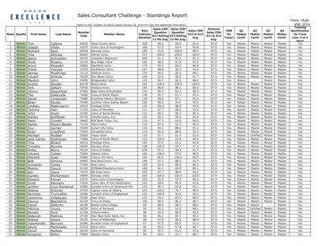
IntroductionConstruction began on the Trans-Alaska Pipeline System (TAPS) in 1974. A few short years later, oilwas flowing from Alaska’s northernmost shore down to the terminal in Valdez. Found along thelength of the pipeline are varying environmental extremes (Brusso, 2018.). These corrosiveenvironmental stresses coupled with erosion from flowing fluids can degrade a pipeline below safelevels in a matter of a few years. According to the National Energy Board of Canada, corrosion is theprimary factor leading to the failure of oil and gas pipelines.Pipeline incidents occur every year, and they are often deadly and expensive. According to the UnitedStates Department of Transportation Pipeline and Hazardous Materials Safety Administration(PHMSA), there have been 11,752 incidents, 331 fatalities, 1,292 injuries with a total cost of 7,298,212,873 in damages from 1998 through 2017. During the same period in the State of Alaskaalone, PHMSA recorded incidents have cost the state of Alaska a total of 79,363,784. (See Exhibit1.) (PHMSA, 2018).Exhibit 1.Total cost of pipeline incidents in the state of Alaska 1998-2017 (PHMSA, 2018).PHMSA’s record keeping shows how pipeline incidents can be costly for states with pipelines.Because in-process welding is a hazardous activity, it is of great importance that companies performwork without incident or injury to personnel, equipment, and the environment. Not all the above-listedincidents involved welding but, each incident that does occur near where welding is taking place is atrisk for becoming a major disaster. Successful execution of this work can lead to opportunities forcontractors to expand their scope of operation and expertise further.7
In-process welding has become a commonly used approach when installing upgrades or makingrepairs to piping systems that are live. Furthermore, it is the preferred choice in procedure forpipelines and piping for the financial benefits. For contractors dealing with process piping, theopportunity to perform repairs on active or previously active piping systems is not always a reality.Not every contractor has the internal processes formalized to perform this work safely andprofitabilityThe need for a standard operating procedure was identified by a group of welding supervisors thathave been subcontracting this type of work. This project focused on combining academic research andfield data to create a living document that will serve as a formalized checklist for in-process welding.Following a formalized guide for in-process welding can help a contractor perform work in a mannerthat is consistent with health, safety, and environmental requirements.The modern construction approach applies scientific principles to project management by mappingand planning all project aspects, utilizing best-known methods. Part of project management dutiesincludes expanding the customer base. Financial opportunities for a contractor with a developed an inprocess welding plan are available. Right now, revenue is being lost by the in-process weldingactivities that get subcontracted to different companies that specialize in this type of work.Explanation of In-Process WeldingWhen piping system damaged is discovered by visual inspection, x-ray or other inspection types,repairs must be made to maintain the integrity of that system. In-process welding is used to repairpiping systems that have damage but are still safe to operate. If the damage found poses an immediaterisk to personnel, the environment, and assets that system is usually shut down as fast and safe aspossible. Usually when this shutdown happens, if the product cannot get diverted, money is lostbecause the system must shutdown. The scenario mentioned above can be avoided in most cases if theappropriate inspection and repair schedules get followed.Three main types of damage that can commonly occur on piping systems are erosion/corrosion, holes,and cracking (See Exhibit 2a.). Erosion is caused by moving fluids on the inside of piping systems.Although this damage is on the inside of piping, it can be fixed utilizing a sleeve repair method and anin-process welding procedure.This project is examining in-process welding for the installation of metal sleeves (Type B) (SeeExhibit 2b.) while excluding newer composite type sleeves (Type A). Type B sleeves will generallybe made of two welded half pieces of pipe that encapsulate the damaged area on a live piping system.These halves are welded directly on to the live lines and then welded together. Once the sleeve repairwelding is completed the space between the damaged pipe and the sleeve are filled with a speciallymade grout. This grout is used to increase the structural integrity of the damaged area.8
Exhibit 2. Three common types of pipe damage (Reliable Pipes & Tubes LTD. 2018).Exhibit 3. Artist depiction of Type B piping sleeve (Reliable Pipes & Tubes LTD. 2018).The continuous flow of profitable product is a core deciding factor in choosing in-process welding forlive repairs. Type B sleeves are usually cheaper, but they cannot be used in piping systems that haveweight restrictions. Depending on the size of the damaged piping, Type B sleeve can exert too muchweight stress.A benefit of this type of repair is that the product flow can be decreased enough to make welding onthe active process safe while the system can remain profitable. This process also reduces the need toutilize hazardous material procedures to clean existing piping. Hazardous material procedures areexpensive and impractical especially on large sections of a pipeline.The United States has roughly 2.5 million miles of pipeline, much of these systems contain liquidsthat are often harmful and deadly (Exhibit 3). Utilizing in-process welding procedures can help9
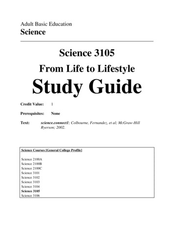
mitigate the risk of exposing people and the environment to these hazards. While using in-processwelding techniques, these hazards can be drastically reduced.Exhibit 4. Pipeline IncidentsThe above top left picture is from a natural gas pipeline explosion on Tuesday, Dec. 5, 2017, outsideof Dixon, Illinois (Alex T. Paschal / AP). The top right photo is the aftermath of a December 11, 2012explosion in West Virginia (National Transportation Safety Board). The bottom left is a picture of10
rescuers in-front of an explosion in Central Mexico on December 19, 2010 (United StatesEnvironmental Protection Agency). The bottom right photo is of the destruction that a Phillips 66pipeline explosion in Paradis, Louisiana on February 9, 2017 (NOLA.)The pictures above show destruction that pipeline explosions can cause. In Dixon, Illinois theexplosion killed two people and critically injured two others. The West Virginia incident was causedby corrosion and malpractice of inspection. This incident in West Virginia demolished three homesand damaged 800 feet of interstate road. This tragedy may have been avoided by utilizing theappropriate pipeline repair practices. The explosion in Central Mexico was caused by illegal and noncompliant pipeline connections. This explosion killed 28 people and destroyed over 100 homes in thearea. The bottom right photo is of the destruction that a Phillips 66 pipeline explosion caused inParadis, Louisiana, killing one person. The cause of the explosion is still under investigation, but ithas been reported that it happened during regular maintenance and that some part of the piping systemfailed.ResearchProject research focused on determining what components a standard operating procedure shouldhave that would lead to reaching a zero percent incident rate while utilizing in-process welding tomake money. Having a zero percent incident rate is imperative for keeping contractors competitive forwinning and retaining new work. On the job casualties and environmental incidents can negativelyimpact a contractor’s ability to make money and gain new work.Interviews were conducted with several individuals that have direct working knowledge of in-processwelding. The goal of this research was to establish what laws, regulations and best practices should befollowed to create a checklist for in-process welding safely.For a contractor to start working on in-process welding as a viable procedure, it was essential toexamine the context and environment by examining laws and regulations, and then narrowing thefocus by talking to industry professionals. The research was analyzed to form an in-process weldingchecklist, so field supervision could have a simple, action-orientated checklist that could help savelives and money. When in-process welding takes place, it requires various crafts and multiplecontractors.Research MethodBecause many professionals are working in the trades with direct knowledge of in-process welding,the best way to solicit information from them was to use face-to-face interviews. A mixture ofprofessionals was selected from various roles in the trades, including certified welding inspectors,11
superintendents, and welders. It was important to include many trades in this process because thedifferent point of views were essential to better understanding the environment and the risks.The following interview questions were used to gather the data needed for the in-process weldingSOP.Interview Questions1. What is your professional title and how many years have you been in that line of work?2. What codes are related explicitly to in-process welding?3. Are there any welding best practices that should be added to a Standard Operating Procedurefor in-process welding?4. What should be done by before an in-process weld?5. What should be done during an in-process weld?6. What should be done after an in-process weld?7. Do you have any lessons learned from previous in-process welding? If so, please explain oneor two of them.8. What are the most likely incidents to happen during in-process welding?The research data gathered was used to create a functioning SOP that would serve as a checklist tofollow before engaging in in-process welding. Some local variables such as inclement weather wereleft out of the SOP so that this document could be used elsewhere.This checklist required information from field personnel as well as various academic works andgovernmental agencies. The databases and publications from these works were used to elaborate onthe findings of the gathered research.Literature ReviewThe American Petroleum Institute (API) is a trade association that supports the natural gas and oilindustry by conducting and publishing research as well as influencing public policy. Their mission isto “promote safety across the industry globally and to influence public policy in support of a strong,viable U.S. oil and natural gas industry” (API, 2018). Their research can offer insight into discoveringsome of the industry’s best practices. API standard 1104 is the Standard for Welding Pipelines andRelated Facilities (API,1999).The API standard 1104 has a section specifically for in-process welding. This section offers insightand best practices for welding on live, pressurized piping systems that have been used for petroleumbased products. This section offers information for establishing processes that can help contractorsmake safe and legal in-process welds (API,1999).12
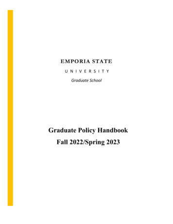
Welding Procedure SpecificationFor a welder to know the details of their scheduled welding scope, they must consult a WeldingProcedure Specifications (WPS), a document that includes variables and requirements for welders tofollow when making actual production welds. This document defines specifics for each type of weld.A welder’s qualification to use a WPS must be stored in a Procedure Qualification Record (PQR)Procedure Qualification RecordThe PQR is where a welder’s test for a specific WPS is recorded. This document shows the materialand other variables that were used during weld testing (Exhibit 4). This document must meet ASMERequirements for in-process welding. These are stored as proof that a welder has taken theappropriate steps to be able to weld in the field. This document is vital for documenting legalrequirements, and it must be completed in-house by each company using them.CONSTRUCTION COMPANYProcedure Qualification Record In-Process WeldingRevision No1SP No.IPWRevision Date:10/10/18Form No.IPWWelderNumber:Part I: To be completed by the JBH CWIA.Code Edition and Addenda:ASME Section IXEdition:Addenda:AWS D1.1:Edition:Addenda:Other Applicable Documents:B.Base Metal:1.Material Spec., Type & Grade:to2.ASME P-No. and Group:to3.Carbon Equivalent:to4.Thickness of Weld Test Coupons:to5.Diameter (if applicable):to6.Water Flowto7.Other Requirements:13
C.Weld Filler Metal:1.ASME Specification:Root:Fill:2.AWS Classification:Root:Fill:3.ASME Weld Metal Analysis A No.Root:Fill:4.ASME Filler Metal Group F No:Root:Fill:5.Filler Metal SizeRoot:Fill:D.Welding Process and Welding Parameters:1.Process:2.Spool Position:3.Water PressureRoot:# of Passes Over Root:Fill:# of Passes:O2 Content of Purge Gas Before Welding:CO24.Preheat Minimum: F5.Interpass Temperature:6.Electrical Characteristics: (List by Welding Process)ProcessCurrent::ProcessCurrent::7.Bead Placement Technique:8.Multipass Technique:9.Welding Position to be Tested: FMaximum (achieve for at least one pass)Polarity:Transfer Mode:Polarity:Transfer Mode:Type of Progression:10.Amperage, Voltage and Travel Speed (per Welding Process and Filler Wire Diameter)Filler MetalProcessPassDiameterAMPSVolts11.Joint Design to Use: (NORMAL JOINT IN-PROCESS DEFAULT)12.Post Weld Heat Treatment: (PWHT)YesTemperature: FTime at Temperature:HrPressureNoPWHT Procedure To Be Used:E.SpeedRev:Tests To Be Performed:1.Mechanical Test:a.Tensile Tests (QW-150)Number of Specimens:YesNoType:Per Fig:14
Locations of Specimens:Acceptance Per:b.psiBend Tests (QW-160)YesNoNumber of Sides Bend Specimens:Per Fig:Number of Face and Root Bend Specimens:Per Fig:Locations of Specimens:Acceptance Per:c.Toughness Tests (QW-170)(Carpy V-Notch):YesNoTest Temperature:Number of Specimens:Base Metal:Weld Metal:Locations of Specimens:Per Figure:Minimum Acceptance:2.Ft/LbsMils Lateral ExpansionMetallographic Testsa.Macro Etch Section Tests:YesNoNumber of Specimens:Inspected at:% MagnificationAcceptance Per:b.Hardness Transverse Tests:YesNoYesNoYesNoYesNoNumber of Specimens:c.Magnetic Verification of DeltaFerrite Tests:Number of Specimens:In-Process – 50% Weld LevelCompletionAcceptance Per:d.Sensitization Tests:Number of Specimens:Acceptance Per:3.Nondestructive Test:Radiographic:Acceptance Per:4.Other Required Tests:JBH AWS CWIDateSeth Loosli PMDate15HAZ
Part II: To be completed by the JBH AWS CWIA.Welder Assigned:B.Start of Welding Date:C.Test Facility:D.Pre-Test InspectionExhibit 5To meet the requirements needed for a PQR that covers in-process welding, a specific welding testmust be taken. In-process welding requires a specific welding test to manage heat-loss from movingliquids. When a live piping system has product flowing, the liquid can affect an in-progress weld byremoving heat from the weld area too quickly. The removal of heat at an accelerated rate can cause aweld to crack or fail. To replicate this phenomenon in the field a particular type of test spool must beused (Exhibit 6).16
Exhibit 6. This is an example of a test spool for welder qualifications on in-process systems (API1999).The heat loss problem is replicated by setting up a test spool like the spool in Exhibit 5. The AmericanPetroleum Institute recommends setting up a similar test spool with flowing water. Thisrecommendation says using flowing water is adequate to address most heat loss issues experienced inthe field, however other liquids can be used if the correct parameters are not being achieved withwater in the test system (API,1999).Weld CrackingHaving duly qualified welders helps avoid two common issues when welding on pressurized pipingsystems. The first issue is the cracking of welds during or after welding. The next issue has to do withthe welding rod penetrating the entire thickness of the piping system. The welding trade refers to thisas burn-through.Weld cracking is common during in-process welding because the moving of liquid takes heat awayfrom the welding area at an increased rate. The hydrogen cracking of welds generally happens whenthe three variables listed below happen: Hydrogen is present in welding material Above threshold tensile strength to the piping system17
Applied welding material microstructure is crack susceptible.To reduce the occurrence of hydrogen cracked welds, a welder must remove or mitigate the abovelisted variables. To reduce hydrogen levels in welding material the WPS should include the use of an18 series rod. The electrodes in this series are considered low hydrogen. Removing tension on apiping system can alleviate cracks. This can be achieved by making sure a piping system is level,plumb and supported according to engineering specifications.To reduce the presence of crack susceptible microstructures, the welding machine heat output shouldbe set as high as the material and specification allows it. Also, if the field situation is suitable for preheating and the temper bead method they should both be utilized (Exhibit 6).Exhibit 7. The temper bead process reduces the prevalence of crack-susceptiblemicrostructuresIf the damaged piping material is too thin, then the upper ranges of acceptable heat output will be toodangerous. If the heat output is too low material cohesion may be reduced to a point where cracksusceptible microstructures are prevalent. The solution for this is to utilize the tempering methodmentioned above (API, 1999).It is now known that speedier welds reduce instances of hydrogen cracked welds. Also, during the last50 years, the composition of electrodes and steel pipe have changed to help reduce this problem.When conducting in-process repairs generally there are no breaks between the start and finish ofwelds (Exhibit 7). This is partially due to the lower heat input ranges required for initial weld passes.It is hypothesized that there is a reduction in hydrogen cracked welds because of the three followingvariables: Reduction in carbon content in materials Increased alloy percentages Piping materials being thicker and allowing more heat18
Exhibit 8. Cracking most often occurs when the weld zone returns to ambient temperature(TWI, 1999).Another way to reduce the prevalence of disasters caused by hydrogen cracked welds is to do athorough inspection after welding is completed. This means that the correct inspection proceduresshould be explicitly created for in-process welding (Exhibit, 8). Furthermore, the same inspectionprocedures should be used during welder qualification and field repairs to account for consistency. Asignificant concern with hydrogen cracking welds is they the effects can sometimes be time delayed.Time should be set aside for this time delay during the final inspection.The American Welding Society (AWS) D1.1 code covers the storage of low hydrogen weldingelectrodes. The storage of low hydrogen welding materials is essential to follow (Exhibit 9). If thiscode is not followed the composition of the low hydrogen material can be compromised, and this canlead to welds that cracks. The AWS set up heat and humidity values to decrease the risk of addingadditional hydrogen to a welding area. Furthermore, it is essential to follow this code because if thewelding materials become contaminated the impurities are not visible to the naked eye. This leads toproblems being discovered too late, and it adds the need for costly rework (AWS, 2005).19
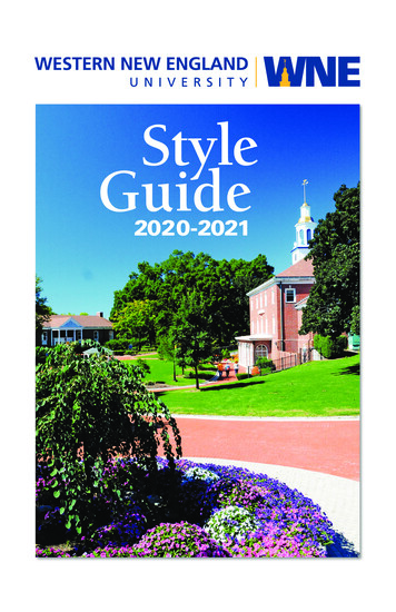
Exhibit 9. Welding electrodes must be monitored to meet code and procedure standardsBurn-throughAs previously mentioned, an increase in heat input is one of the ways to combat the hydrogen inducedcracking welds commonly associated with the in-process welding procedure. This technique does notcome without its risks. Because in-process welding is often done on damaged piping systems, there isan increase in the chances that the welding electrode can penetrate the piping material. When thisburn-through happens on pipes with an outside diameter of 2.375 inches or greater, it is considered awelding defect (Exhibit, 10). Moreover, during in-process welding, this can lead to a release ofprocess or an explosion (API, 1999).20
Exhibit 10. Weld coupons with different degrees of burn-through defect: (a) weld coupon No. 1; weldcoupon No. 2; and (c) weld coupon No. 3. (NLM, 2018).Welding burn-through is common in damaged piping areas. It is up to the welder to have the skillsnecessary so that burn-through does not turn into a catastrophic event that leads to the loss of life anddamage to the environment. Another way to ensure the welder has done the job properly is to have aninspection plan. An inspection plan starts before welders start welding and ends after the welding iscomplete.In-Process Welding in the FieldBeforeIn-Process welding takes several different crafts must prepare. Once this preparation is made it is timeto begin the most immediate in-process welding procedures. It is recommended that the welding scopepackage is set-up through a document control process to keep track of who and when information isbeing accessed. Next, the field system should be field-verified against the WPS. At this time, theinitial NDE requirements listed in the WPS should be executed. Once the piping system repairlocation has been through the NDE process, it should be labeled and recorded in the scope package.DuringWhen the NDE comes back, and workers are mobilized to start the actual in-process welding the nextphase can begin. It is recommended that if the NDE comes back within the acceptable parameters, it isreverified in the field. At this point in the process, the piping system operations team should havereduced the operating pressure of the piping system so that it can be welded. The actual live pressureshould be checked, and then a heat loss test can be performed. This test should be performed in frontof in-house and client Quality Assurance/Quality Control (QA/QC). These steps can help limit thechances for hydrogen cracking to occur.The next steps should also be followed to reduce hydrogen cracking. All welding materials should befield verified to meet the piping system and WPS. This includes the repair sleeve material andwelding electrodes. At this stage, it is recommended to check the welders for the correct WPQ. Onceall materials and welders are verified a Hot Work Permit (HWP) can be signed, and in-house andclient supervision can be notified that welding has started.The last step is to verify heat-loss values to make sure they stay within parameters. This last stepwhile the welding is taking place is designed to reduce the chance of a welder burning-through thepiping system material. Thus, avoiding a potentially catastrophic incident that would be detrimental tothe health safety of employees and the environment.21
AfterAfter the welders have finished the QA/QC can visually inspection all the welds that were made.Additional NDE that is piping system specific will be carried out if all the welds have passed visualinspection. Because the lines are still live, the weld will need to pass an in-service welding test. Thismeans the pressure will be turned up above normal operating pressure to make sure the weld willsurvive its regular activity. If the weld holds against the pressure, the in-process welding cycle isalmost complete (Exhibit 11). The system can be returned to normal operating pressure, and the finalsignatures on the scope and hydrostatic testing packages can be done at this time. The hydrostatic testshould include at least the date of the test, the piping system identifiers which includes which processfluid and the test pressure.ConclusionsThis project has created a useable standard operating procedure that will help the client make moneyby allowing them to bid for in-process work and by helping them stay safe while conducting this workwith the help of the project sponsor and those that participated in data collection. The standardoperating procedure that was created includes steps that help employees follow the welding laws andregulations as well as industry best practices.RecommendationsThe American Petroleum Institute cites that the first significant pipeline boom began in the 1920s.The process of repairing piping systems soon follow. The materials and processes have been updatingsince then. The piping system repair field is changing. In the future contractors might benefit fromusing newer methods and materials than what is cited in this project.Because of the limitations of the project sponsor, none of the newer methods of piping system repairwere included in this project. Another limitation of this project was that none of the participants weretrained engineers. Further studies could expand research by including engine
Exhibit 8. Cracking most often occurs when the weld zone returns to ambient temperature (TWI, 1999). 19 Exhibit 9. Welding electrodes must be monitored to meet code and procedure standards 20 Exhibit 10. Weld coupons with different degrees of burn-through defect: (a) weld coupon No. 1; weld coupon No. 2; and (c) weld coupon No. 3. (NLM, 2018). 21