Transcription
SystemVerilog AssertionsAre For Design Engineers, Too!Don MillsLCDM EngineeringSalt Lake City, Utahmills@lcdm-eng.comStuart SutherlandSutherland HDL, Inc.Portland, Oregonstuart@sutherland-hdl.com
LCDMPresentation OverviewEngineering& Why engineers don’t do assertions Excuses, excuses, excuses SystemVerilog Assertions overview Immediate assertions Concurrent assertions Where assertions should be specified Where to put the assertion code Who should write the assertions Developing an assertions test plan Assertions for Design Engineers Verifying design assumptions Examples, examples, examples Lessons Learned2 of 23
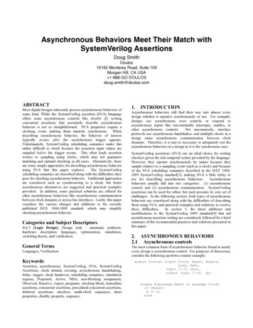
LCDMCase Study:Assertions for a Small DSP&Engineering A small Digital Signal Processor (DSP) design is used in this presentation to illustrate how to use SystemVerilog AssertionsThe DSP contains A clock generator andregisterclock genreset synchronizerA state machineSeveral registersA program counterCombinatorial decoder and ALUProgram and data memoriesA tri-state data busramregisterpc The DSP is used as a training lab in Sutherland HDL courses Synthesis students get to model the DSP as a final project Assertion students get to add assertions to the DSP and testbenchalucontrollerdecoderstatus regramiobufiobuf3 of 23
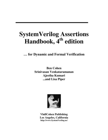
Assertion-like Checks Can BeWritten in Plain VerilogLCDMEngineering& An assertion is a design condition that must be true Assertions can be written in Verilog, but It’s a lot of extra code!012345reqackEachEach requestrequest mustmust bebe followedfollowed byby ananacknowledgewithin1to3clockcyclesacknowledge within 1 to 3 clock cyclesToTo testtest forfor aa sequencesequence ofof eventseventsrequiresrequires severalseveral lineslines ofof VerilogVerilog codecode DifficultDifficult toto write,write, readread andand maintainmaintain CannotCannot easilyeasily bebe turnedturned offoff duringduringresetreset oror otherother don’tdon’t carecare timestimesalways @(posedge req) begin@(posedge clk) ; // synch to clockfork: watch for ackparameter N 3;begin: cycle counterrepeat (N) @(posedge clk); display("Assertion Failure", time);disable check ack;end // cycle counterbegin: check ack@(posedge ack) display("Assertion Success", time);disable cycle counter;end // check ackjoin: watch for ackend4 of 23
Verilog-based Checker’sMust be Hidden from SynthesisLCDMEngineering& A checking function written in Verilog looks like RTL code Synthesis compilers cannot distinguish the hardware model fromthe embedded checker code To hide Verilog checker code from synthesis compilers, extrasynthesis pragma’s must be added to the codeif (if condition)RTL// do true statementsRTL codecodeelse//synthesis translate offif (!if condition)checkerchecker codecode//synthesis translate on// do the not true statementsRTLRTL codecode//synthesis translate offelse display("if condition tested either an X or//synthesis translate onHowHow manymany engineer’sengineer’s willwill gogo totothisthis muchmuch extraextra efforteffort toto addaddembeddedembedded checkingchecking toto ananif elseif else RTLRTL statement?statement?Z");checkerchecker codecode5 of 23
Obstacles to WritingSelf-Checking RTL CodeLCDMEngineering& There are a number of reasons design engineers are reluctant toembed self-checking code within synthesizable RTL models Not enough time in the design scheduleMakes the RTL code hard to readNot synthesizableMight inadvertently change design behaviorWill slow down simulationIt’s the verification team’s jobThese Are Valid Concerns!SystemVerilog Assertionsovercome all of these obstacles!6 of 23
Advantages ofSystemVerilog AssertionsLCDMEngineering& SystemVerilog Assertions have several advantages over codingassertion checks in Verilog Concise syntax! Dozens of lines of Verilog code can be represented in one line of SVA codeIgnored by Synthesis! Don’t have to hide Verilog checker code within convolutedtranslate off / translate on synthesis pragmasCan be disabled! SystemVerilog assertions can be turned off during reset, or untilsimulation reaches a specific simulation time or logic state Can have severity levels! SystemVerilog assertion failures can be non-fatal or fatal errors Simulators can enable/disable failure messages based on severity7 of 23
LCDMSystemVerilog HasTwo Types of AssertionsEngineering& Immediate assertions test for a condition at the current timegenerategenerate aa fatalfatal errorerror statestatevariablevariable isis notnot aa one-hotone-hot valuevaluealways @(state)assert ( onehot(state)) else fatal;AnAn immediateimmediate assertionassertion isis thethe samesame asas anan if elseif else statement,statement, butbut withwith assertionassertion controlscontrols Concurrent assertions test for a sequence of events spread overmultiple clock cyclesaa complexcomplex sequencesequence cancan bebedefineddefined inin veryvery conciseconcise codecode012345reqacka reqack: assert property (@(posedge clk) req ##[1:3] ack;) else error;OneOne lineline ofof SVASVA codecode replacesreplaces allall thethe VerilogVerilog codecode inin thethe exampleexample threethree slidesslides back!back!8 of 23
LCDMAssertion Severity LevelsEngineering& The severity of an assertion failure behavior can be specified fatal [ ( finish number, “message”, message arguments ) ] ; Terminates execution of the tool finish number is 0, 1 or 2, and controls the information printed by the tool upon exit(the same levels as with finish) error [ ( “message”, message arguments ) ] ;SoftwareSoftware toolstools maymay A run-time error severity; software continues executionprovideprovide optionsoptions toto warning [ ( “message”, message arguments ) ] ;suppresssuppress errorserrors ororwarnings A run-time warning; software continues executionwarnings oror bothboth info [ ( “message”, message arguments ) ] ; No severity; just print the messagealways @(negedge reset)assert (state LOAD)else fatal(0,“FSM %m behaved badly at %d”, time);always @(negedge reset)assert (state LOAD) else warning;9 of 23
Expression Sequencesand the ## Cycle DelayLCDMEngineering& A sequence is a series of true/false expressions spread over oneor more clock cycles ## represents a “cycle delay” Specifies the number of clock cycles to wait until the nextexpression in the sequence is evaluatedproperty p request grant;@(posedge clock) request ##1 grant ##1 !request ##1 !grant;endproperty“@(posedge“@(posedge clock)”clock)” isis notnot aa delay,delay, itit specifiesspecifies whatwhat #### representsrepresentsap request grant : assert property (p request grant); else fatal; requestrequest mustmust bebe followedfollowed oneone clockclock cyclecycle laterlater byby grantgrant grantgrant mustmust followedfollowed oneone clockclock cyclecycle laterlater byby !request!request !request!request mustmust bebe followedfollowed oneone clockclock cyclecycle laterlater byby !grant!grant10 of 23
SystemVerilog Design ConstructsWith Built-in AssertionsLCDMEngineering& Some SystemVerilog constructs have built-in assertion-like checking! always comb / always ff Allows tools to check that procedural code matches intent Check that procedural block variables are not written to elsewhere unique case / unique if else Check that decision statements are fully specified Check that decision branches are mutually exclusive Enumerated variables Check that assignments are within the legal set of values Check that two or more labels (e.g. state names) do nothave the same valueBy using these constructs, designer’s get the advantages ofself-checking, without having to write assertion statements!11 of 23
LCDMWhat’s NextEngineering&9 Why engineers don’t do assertions Excuses, excuses, excuses9 SystemVerilog Assertions overview Immediate assertions Concurrent assertions Where assertions should be specified Where to put the assertion code Who should write the assertions Developing an assertions test plan Assertions for Design Engineers Verifying design assumptions Examples, examples, examples12 of 23
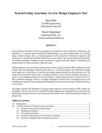
LCDMAssertions for theDSP Examplesys clkext clk(from test bench)clock genload bloadctl clkext rstNregister16rstN(from test bench)b data[15:0]data [15:0]dpc cnt[11:0]sys clkaddrvccloadregister16iw data[15:0]ddatardN programmemorysys clkfetchregister clkwrNrstNvccinc pciw [15:0]loadincqsys clk clkq code[2:0]rstNaluopcodexbitresultrstNalu out [15:0]xbitzbitzbitdout oeNset ro flagzero flagbranchingctl clkload sload bload bload fload fload pcbranching clkload sinc pcset brset brdout oeNhaltrstNrstNdmem rdNdmem wrNALUoperationdecodeload pcinc pcrslt oeNinstructionopcodehaltdmem rdNdmem wrNsys clkrstNloadrdNwrNdataz inb ind instatus reg clkrstN r regx reg z reg b reg d regbranchingzero flagexceptiondata rdyN(instance“dmem”)addrx inr inramrslt oeNdout oeNload sdata [15:0]gndload pciw [11:0](instance“pmem”)load fiw [15:12]ram&Engineeringresult [15:0]iobufiobufdata out[15:0]datamemoryrslt oeN13 of 23
Where AssertionsCan be Specified SystemVerilog Assertions can be LCDMEngineering&AssertionAssertion BasedBased VerificationVerificationshouldshould taketake advantageadvantage ofof allall ofofthesethese capabilitiescapabilities Embedded in the RTL code Executes as a programming statement, in-line with the RTL procedural code Will be ignored by synthesisIn the design model, as a separate, concurrent block of code Executes in parallel with the design code throughout simulation Will be ignored by synthesisExternal to the design model, in a separate file Can be bound to specific instances of design models Executes in parallel with the design code throughout simulation Allows verification engineers to add assertions to the designwithout actually modifying the design code Synthesis never sees the assertion code14 of 23
LCDMGuideline!Engineering& Design engineers should write assertions to verify assumptions thataffect the functionality of a design block The assertion documents the designer’s assumptions Example: The ALU block assumes that the A, B and opcode inputs willnever have a logic X or Z value Verification engineers should write assertions that verify designfunctionality meets the overall design specification The assertion verifies that the designer correctly implemented thespecification Example: The zero flag output of the ALU block should always be set ifthe ALU result output is zero15 of 23
Developing An AssertionsTest PlanLCDMEngineering& Before writing assertions, you need an “Assertions Test Plan” Specifies what functionality needs to be verified with assertions What type of assertion is needed for each test Immediate or concurrent? Where the assertion should be placed Embedded in the design? At the system interconnect level? Bound into the design? Which team is responsible for writing each assertion The verification team? The design team?TheThe AssertionsAssertions TestTest PlanPlan shouldshould bebe developeddeveloped beforebefore anyany designdesign codecode isis written!written!16 of 23
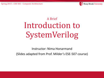
An Assertions Test PlanExampleLCDMEngineering& The assertions test plan defines What to verify Which team is responsible for writing the assertion Example: Program Counter assertions test planFunctionality to VerifyAssigned Toload and increment are mutually exclusivedesign teamIf increment, then d input never has any X or Z bitsdesign teamIf !load and !increment, then on posedge of clock, pc does not change (must allowfor clock-to-q delay)verification teamIf increment, then pc increments by 1 (must allow for clock-to-q delay)verification teamIf load, then pc d input (must allow for clock-to-q delay)verification teamEachEach designdesign blockblock hashas aa similarsimilar assertionsassertions testtest planplan17 of 23
Assertion Plan Example 1:Assertions on ALU InputsLCDMEngineering& ALU design engineer assertions exampleFunctionality to VerifyAssigned ToAfter reset, the A, input never have any X or Z bitsdesign teamAfter reset, the B input never have any X or Z bitsdesign teamAfter reset, the opcode input never have any X or Z bitsdesign teamAll instructions are decodeddesign team always comb begin// Check that inputs meet design assumptions (no X or Z bits)ai a never x:assert ( a ! 1'bx);ai b never x:assert ( b ! 1'bx);ai opc never x: assert ( opcode ! 1'bx);unique case (opcode) // “unique” verifies all opcodes are decoded. // decode and execute operationsDesignDesign engineerengineer assertionsassertions areareendcasesimplesimple toto add,add, andand cancan greatlygreatlyendreducehard-to-finderrors!reduce hard-to-find errors!18 of 23
Assertion Plan Example 2:State Machine AssertionsLCDMEngineering& FSM design engineer assertions exampleFunctionality to VerifyAssigned ToState is always one-hotdesign teamIf !resetN (active low), state RESETdesign teamIf in DECODE state, prior state was RESET or STOREdesign teamproperty p fsm onehot; // FSM state should always be one-hot@(posedge clk) disable iff (!rstN) onehot(state);endpropertyap fsm onehot: assert property (p fsm onehot);property p fsm reset; // verify asynchronous reset to RESET state@(posedge clk) !rstN - state RESET;endpropertyap fsm reset: assert property (p fsm reset);property p fsm decode entry; // verify how DECODE state was entered@(posedge clk) disable iff (!rstN) state DECODE - ConcurrentConcurrent assertionsassertions past(state) RESET past(state) STORE;cancan bebe usedused toto verifyverifyendpropertycoveragetoo!coverage too!ap fsm decode entry: assert property (p fsm decode entry);19 of 23
LCDMLessons Learned Engineering& Teaching engineers how to add assertions to the DSP training labhas shown that It takes time to write the assertions test plan It is not a trivial task, but it is critical to successfully using SVA! The assertion test plan helps identify similar assertions Can write an assertion once, and use it in several places Assertions should not just duplicate the RTL code Engineers need to learn to think differently Disabling assertions during reset is important Hundreds of false assertion failures occur in the DSP during reset The test plan needs to be flexible Some times the responsibility for which team should write theassertion needs to change20 of 23
MoreLessons Learned LCDMEngineering& Assertions may require different design partitioning The DSP ALU block is difficult to check with concurrent assertionsbecause it is pure combinational logic (no clock) Better design partitioning would put the ALU and its input and outputregisters into one design block Enumerated type definitions should be defined globally The DSP state machine uses a local enumerated variable for thestate names Assertions written external to the state machine cannot access thoseenumerated names Enumerated types should have explicit values defined for each label After synthesis, labels disappear and only logic values exist Assertions become invalid if the label does not have an explicit value21 of 23
LCDMSummaryEngineering& SystemVerilog Assertions enable true assertions based verification Integrated into the Verilog/SystemVerilog language Don’t have to hide assertions in comments Assertions have full visibility to all design code Execution order is defined within simulation event scheduling Easy to write (compared to other assertion solutions) Immediate and concurrent assertions A concise, powerful sequential description language Sequence building blocks for creating complex sequences Binding allows verification engineers to add assertions to a design without touching the design filesSystemVerilog assertions are a team effort Some assertions written by the design team Some assertions written by the verification team22 of 23
LCDMQuestions & Answers Engineering&What will assertions reveal about my design?23 of 23
SystemVerilog Design Constructs & With Built-in Assertions Some SystemVerilog constructs have built-in assertion-like checking! By using these constructs, designer's get the advantages of self-checking, without having to write assertion statements! always_comb/ always_ff Allows tools to check that procedural code matches intent