Transcription
AF Presentation October 2016 Version, By Samy Faried, PEArc Flash Regulations and MitigationUpdate ABBMonth DD, YYYY Slide 1
ABB Inc.December 18, 2017 Slide 2 Speaker name:Samy Faried, PE Speaker title:Regional Bus. Dev. Manager/Field Application Engineer Company name:ABB Location:Ft. Myers, FL Telephone Number239-560-1094
AgendaI.II. ABBDecember 18, 2017 Slide 3Electrical HazardsRegulation ChangesIII.Highlights of OSHA’s Final RuleIV.ABB Approach for Performing the Arc Flash StudyV.Mitigating Risk Hazards
I. Electrical Hazards ABB GroupDecember 18, 2017 Slide 4 ABBDecember 18, 2017 Slide 4
I. Electrical Hazards Video:Internal arc test50kA / 1s Switchgearwithout rcompartment ABBDecember 18, 2017 Slide 5
Types of Electrical Hazards Electric shock Prohibitive space (eliminated) Restricted space Limited spaceArc flash (Category 1 to 4) Burns Lethal at 10 feetArc blast ABB GroupDecember 18, 2017 Slide 6 ABBDecember 18, 2017 Slide 6
Arc Flash – How Big Is the ProblemArc flash incidents occur five toten times daily 6,000 Fatal electrical injuriesbetween 1992 and 2013 80% of electrical accidents arecaused by arc flash / arc blast24,000 Non-fatal electricalInjuries between 1992 and 2013 ABB GroupDecember 18, 2017 Slide 7 ABBDecember 18, 2017 Slide 7
Best Way to Understand Arc FlashHow fast; how intense?Arc Energy Volts X Amps X Time ABB GroupDecember 18, 2017 Slide 8 ABBDecember 18, 2017 Slide 8
Final Rule Forecasted Annual Impact 20 lives saved 118 serious injuriespreventedDr. David MichaelsUS Dept. of LaborOSHA ABB GroupDecember 18, 2017 Slide 9 ABBDecember 18, 2017 Slide 9
Codes and Standards ABB GroupDecember 18, 2017 Slide 10 ABBDecember 18, 2017 Slide 10OSHA 29CFR 1910.269 - General Industry 1926 Subpart V - Construction NFPA 70 National Electric Code NFPA 70E Standard for Electrical Safety in the Workplace NESC National Electric Safety Code IEEE Standard 1584 Guide for Performing Arc FlashHazard Calculations
Regulators’ ConflictsNFPA 70E 2015 “Standard for Electrical Safety in theWorkplace”The new standard includesthe following: ABB GroupDecember 18, 2017 Slide 11 ABBDecember 18, 2017 Slide 111.Elimination of PPE for allwell installed and wellmaintained equipment inclosed door operations2.New tables for arc-ratedPPE3.Table use is limited;calculations emphasized
Regulation SenseIf the goal is safety ofworkers and equipment,regulations without thewisdom of experience canbe hazardous. ABB GroupDecember 18, 2017 Slide 12 ABBDecember 18, 2017 Slide 12
II. Regulation Changes ABBDecember 18, 2017 Slide 13
Regulation Changes (1 of 2)A. The new law emphasizes the employer’sresponsibility.Example: Rule 1910.269(q)(2)(vii)Old Rule: Pulling lines and accessories shall berepaired or replaced when defective.New Rule: The employer shall repair or replacedefective pulling lines and accessories.B. New law is applicable to all construction work.C. “Utility” is “Host Employer”D. “Contractor” is “Contract Employer”E. “Hazard Analysis” is “Risk Assessment” (To becompleted by April, 2015) ABB GroupDecember 18, 2017 Slide 14 ABBDecember 18, 2017 Slide 14
Regulation Changes (2 of 2)F. Use four approved calculation methods for incidentenergy.G. Arc rated head and face protection is required for 9 Cal/cm2 single-phase open air 5 Cal/cm2 three-phase.H. Foot protection is required. ABB GroupDecember 18, 2017 Slide 15 ABBDecember 18, 2017 Slide 15
Example of Final Rule Changes1.General training determined by risk (Required every 3 years, NFPA 70E - 2012)2.Host employers and contractor employers3.Fall protection (April 1, 2015)4.Minimum approach distance and insulation (April 1, 2015)5.Protection from flames and electric arc hazard (January 1, 2015)Employers MUST estimate incident energy based on specific calculationmethods, and must provide protective equipment.6.Deenergizing T&D lines and equipmentMultiple crew coordinate under a single worker7.Protective grounding for deenergized lines 8. OSHA announced delay in citations for compliance until October 31, 2014. ABB GroupDecember 18, 2017 Slide 16 ABBDecember 18, 2017 Slide 16
III. Highlights of OSHA’s Final Rule ABBDecember 18, 2017 Slide 17
Final Rule Became Law July 10, 2014 ABB GroupDecember 18, 2017 Slide 18 ABBDecember 18, 2017 Slide 181.General training determined by risk (Required every 3years, NFPA 70E - 2015)2.Host employers and contractor employers3.Fall protection (April, 2015)4.Minimum approach distance and insulation (April, 2015)5.Protection from flames and electric arc hazard (April,2015) study:Employers MUST estimate incident energy based onspecific calculation methods, and must provide protectiveequipment.6.Deenergizing T&D lines and equipmentMultiple crew coordinate under a single leader7.Protective grounding for deenergized lines
Final Rule Became Law July 10, 2014Four methods for calculating incident energies1.2. ABB GroupDecember 18, 2017 Slide 19 ABBDecember 18, 2017 Slide 19NFPA 70E, Annex D 2012“Predicting Incident Energy to Better Manage the ElectricArc Hazard on 600 V Power Distribution Systems”Doughty, T.E. Neal & Floyd II3.IEEE 1584-2002, 1584a-2004 & 1584b-20114.ARCPRO, commercial software (Kinectrics, Inc.)
IV. ABB Approach For PerformingArc Flash Studies ABBDecember 18, 2017 Slide 20
1. Data, Existing Models, and Information Collection ABB GroupDecember 18, 2017 Slide 21 ABBDecember 18, 2017 Slide 21 Existing models for generation, transmission, anddistribution systems. One lines diagrams and layouts for substations. Existing and proposed load data. Equipment specifications and rating. Impedances of transformers, cables, etc. Protective system specifications and clearing time.
2. Modeling and Analysis ABB GroupDecember 18, 2017 Slide 22 ABBDecember 18, 2017 Slide 22 Identify utility and generation power sources and characteristics. Create the system model showing power sources, transmissionand distribution interconnection. Calculate short circuit momentary and interrupting currents. Identify protective equipment and coordination study for thefacilities. Provide all relay types, CT ratios, manufacturers, and settings. Define operating scenarios for tie breakers open/closed. Determine in cooperation with client any assumptions regardingmissing information. Perform arc flash study hazard analysis.
3. Quantifying Hazard Levels & Client Practice ABB GroupDecember 18, 2017 Slide 23 ABBDecember 18, 2017 Slide 23 Perform arc flash hazard analysis according to existingregulations including IEEE 1584. Retrieve short circuit calculations and clearing times ofphase over current devices. Calculate incident energy and arc flash protectionboundaries at all significant locations where work could beperformed on energized parts. Specify safe working distances based on calculated arcflash boundary (incident energy less than 1.2 Cal/cm2. Discuss client practice and interview operation andmaintenance personnel. Recommend personal protective equipment, training, safepractice, labels, and arc flash labels.
4. Deliverable Report and Recommendations ABB GroupDecember 18, 2017 Slide 24 ABBDecember 18, 2017 Slide 24 Collected data and assumptions Coordination study and protective device settings Incident energy and arc flash boundaries Determine adequacy of existing breakers, relay andprotective device settings and providing mitigating solutionsrecommendations. Providing required warning labels
V. Mitigating Risk Hazards ABBDecember 18, 2017 Slide 25
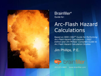
Single line diagram – Where to install AFmitigating devicesUtilityMV BUSMV BREAKER50Ownership boundary51OIL or DTXFMRLV CLASS L CLFBONDING JUMPERUFESPlantPOWER CABLESREALV EQUIPMENT26 ABBDecember 18, 2017 Slide 26Arc Energy Volts X Amps XTime
Four methods for controlling risks ABB GroupDecember 18, 2017 Slide 27 ABBDecember 18, 2017 Slide 271.Reduce fault current or reduce arc voltage2.Reduce duration of the arc (clearing time)3.Increase working distance4.Minimize personnel exposure/presence
1. Reducing Fault CurrentReducing fault current is difficult after system is in place, butthere are some changes that can be made ABB GroupDecember 18, 2017 Slide 28 ABBDecember 18, 2017 Slide 28 For a new design: Reduce transformer size and/orincrease transformer impedance Deploy electronically actuated current limiters Install current-limiting fuses Install current-limiting reactors
IEEE 1584 Guide Equations – Arcing Current For System Voltages below 1kV the following equation is solved:log10 Ia K 0.622log10Ibf 0.0966V 0.000526G 0.5588V(log10Ibf)0.00304G(log10Ibf) For System Voltages of 1kV and higher the following equation is solved:log10 Ia 0.00402 0.983log10Ibf Where: Ia Arcing Current in kA G Conductor Gap in mm, (typical values provided in IEEE 1584 Guide) K -0.153 for open air arcs, -0.097 for arc in a box V System Voltage in kV Ibf bolted three-phase fault current kA, rms symmetrical ABBDecember 18, 2017 Slide 29
IEEE 1584 Guide Equations – Normalized IncidentEnergy So now that we have determined the Arcing Current, let’s look at the Incident EnergyEquation at working distance (normalized at 24 Inches) for an arc time of 0.2secondslog10 En K1 K2 1.081 log10 Ia 0.0011G Where:En Incident Energy in J/cm2 normalized for time and distanceCf Calculation factor 1.0 for voltages above 1 kV, 1.5 at or below 1kVK1 -0.153 for open air arcs, -0.097 for arc in a boxK2 0 for ungrounded systems and -0.0113 for grounded systemsG Conductor Gap in mm, (typical values provided in IEEE 1584 Guide) ABBDecember 18, 2017 Slide 30
IEEE 1584 Guide Equations – Incident Energy(continued) Conversion from normalized values gives the Equation:E 4.184CfEn(t/0.2)(610x/Dx) Where:E Incident Energy in J/cm2Cf Calculation factor 1.0 for voltages above 1 kV, 1.5 at or below 1kVt Arcing time in secondsD Distance from the arc to the person, working distance from IEEE 1584x Distance Exponent from IEEE 1584 factors for equipment ABBDecember 18, 2017 Slide 31
IEEE 1584 Guide Equations – Arc Flash Boundary Calculate the Arc Flash Protection Boundary:DB (4.184CfEn(t/0.2)(610x/EB))1/x Where:DB Arc Flash Protection BoundaryEB Incident Energy in J/cm2 at the distance of the arc flash protection boundary,which is set at 5 J/cm2 (1.2 Cal/cm2) for bare skin (no hood) or at the rating of theproposed PPE ABBDecember 18, 2017 Slide 32
Electronically Triggered Fault Current Limiters(ET-FCL) ABBDecember 18, 2017 Slide 33The ET-FCL is a fast operating interrupting device(intelligent switch) that limits the short circuit current to alevel that breakers and buses can withstand, thereforeprotecting them from damage. 0.6 ms peak current limiting time at first current rise 1/27th of a cycle Warp speed! Comparison: MPR’s instantaneous relay is 1.0 cycle;standard 3 cycle breaker 4 cycles of fault current Bow & arrow vs. rifle shot
ET-FCL, 15kV, 3000A on Roll-in Truck ABBDecember 18, 2017 Slide 34
ET-FCLSingle pole cut-away ABBDecember 18, 2017 Slide 35
ET-FCL: single pole cut awayAfter bursting bridge ABBDecember 18, 2017 Slide 36
ET-FCL – How It Works ABBDecember 18, 2017 Slide 37
RatingsRatedVoltage0.75 kV12.00 kV17.50 kV24.00 kV36.00 kV40.50 kVRatedCurrent* (FLA). . . . . 5000 A. . . . . 4000 A. . . . . 4000 A. . . . . 3000 A. . . . . 2500 A. . . . . 2500 ASwitchingCapability (RMS). . . . . 140 kA. . . . . 210 kA. . . . . 210 kA. . . . . 140 kA. . . . . 140 kA. . . . . 140 kA*For higher rated currents, IS-limiterscan be connected in parallel ABBDecember 18, 2017 Slide 38
Short Circuit vs. Over Currenti11.2.3.2(didt )2(didt )33ilimitt ABBDecember 18, 2017 Slide 39Short-circuit currentwithout ET-FCLShort-circuit current– ET-FCL trippedOver current– ET-FCL NOT tripped
Trip TimingT0: Reaching time for tripping criteria(instantaneous value and di/dt).T1: Response time of the electronic approx. 15 µsiiCT2: Time for opening the burstingbridge and for commutatingthe current to the fuse element approx. 85 µsiBT3: Melting time of the fuse element approx. 500 µsT4: Arc durationiAiA: Tripping criteria are reached(instantaneous value and di/dt).iB: Current at beginning of fuse element's meltingiC: Let-through currentT0 ABBDecember 18, 2017 Slide 40.T1T2 T3T4t
Main-Tie-Main System ApplicationNotes: All mains and ties are operated normally closedET-FCL set to protect all feeder breakersThree winding sources are also applicable ABBDecember 18, 2017 Slide 41
ET-FCL MV Switchgear “System-Wide” Solutions Construction cost reduction tool (MV cable size reduction; lower cost switchgear; lower CTclass applied; smaller switchgear footprint; possible smaller building) A voltage regulation device Protective relay coordination improvements Tighter protection systems via adjusting protective relay time dials Ease of large MV motor starting; questionable need for MV soft starters Harmonic mitigation Arc flash mitigation device Full, MVA rated, N-1, MV bounceless transfer system Inter-buss disturbance immunity Synchronous motor stability improvement All solutions available in the same time frame; marginal tradeoffs betweenthem ABBDecember 18, 2017 Slide 42
Advantages of Current Limiters ABBDecember 18, 2017 Slide 43 Construction cost reduction tool (MV cable size reduction;lower cost switchgear; lower CT class applied; smallerswitchgear footprint; possible smaller building) Arc flash mitigation device A voltage regulation device; Full, MVA rated, N-1, MVbounceless transfer system; Interbuss disturbanceimmunity; Sync motor stability improvement Harmonic mitigation
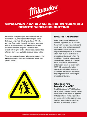
Grounding Switches (UFES)Application descriptionMV BUSMV BKR5051MV “E” RATEDFUSEUFESDT XFMRDT XFMRLV BUSN/A SYSTEMLV BUSAPPLICABLESYSTEMApplication with a primary MV fused switch, a fast acting earthing switch can be applied at anylocation between the fuse’s load side and the transformer’s primary connection. Can operateas fast as 4 ms, therefore magnitude of the LV fault level can potentially be HRC-1 ABB GroupDecember 18, 2017 Slide 44 ABBDecember 18, 2017 Slide 44
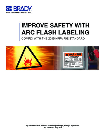
ABBDecember 18, 2017 Slide 45
Three line diagram - MVsolution46 ABBDecember 18, 2017 Slide 46
Three line diagram - MV solution47 ABBDecember 18, 2017 Slide 47
Three line diagram - MVsolution48 ABBDecember 18, 2017 Slide 48
Three line diagram - MVsolution49 ABBDecember 18, 2017 Slide 49
Light Detection Protection ABB GroupDecember 18, 2017 Slide 50 ABBDecember 18, 2017 Slide 50 Light detection protection is based on bothoptical light and phase overcurrent orground overcurrent. It uses fiber optics technology to sense thelight flash and enable very short clearingtimes (AND/OR) technology. Since many arc faults start as a singlephase fault, the neutral current should bemeasured. This results in clearing the faultin early stages.
Arc Flash Detection RelayApplication example – feederREA101REA105 ABBDecember 18, 2017 Slide 51REA105REA101REA105REA105 Arc in a cable compartment Relay detects light Both relays detect overcurrent Both relays send the currentinformation to all connectedunits Only the affected feederbreaker is opened
Effects of an Internal Arc FaultNew active protection using grounding switchesFast Grounding Switch A device as small as a 24 kVinsulator offers enhancedprotection for your switchgear byminimization such effects The arc protection systemchannels the uncontrolled releaseof energy by the arc into a solidmetal, 3-phase connection to earthpotential The internal arc will beextinguished within an operationtime of 4 ms after detection ofthe fault ABBDecember 18, 2017 Slide 52
Switching PrinciplePosition after trippingService position ABB GroupDecember 18, 2017 Slide 53 ABBDecember 18, 2017 Slide 53VacuuminterrupterMovingdirectionDriveCurrent flowafter tripping
A New Way to Approach Arc Fault MitigationTest of ABB’s grounding system “UFES” ABBDecember 18, 2017 Slide 54 LV circuit breaker compartment before and after initiation ofa 60kA arc Arc eliminated by active UFES protection
Test 5 Details55 ABBDecember 18, 2017 Slide 55
2. Reduce Duration of the Arc (Clearing Time) ABB GroupDecember 18, 2017 Slide 56 ABBDecember 18, 2017 Slide 56 Maintenance switch (LV) Zone selective interlocking Bus differential Fast earthing switches Light detection relay (REA) Current Limiters4 ms 2.5 ms0.6 ms
Incident Energy Key Equation x t 610 E 4.184C E xf n 0 .2 D Eis the incident energy (cal/cm2) Cfis a calculation factor 1.0 for voltages above 1 kV 1.5 for voltages at or below 1 kV Enis the energy normalized for a specific time and distance (cal/cm2)dependent on the available fault current & physical equipment tis time in (seconds) REDUCE xis a distance exponent (lookup from IEEE table) Dis the distance from the possible arc point (mm) INCREASE ABB GroupDecember 18, 2017 Slide 57 ABBDecember 18, 2017 Slide 57
Options to Reduce Clearing Time ABB GroupDecember 18, 2017 Slide 58 ABBDecember 18, 2017 Slide 58 Reconfigure protective relay schemes, settings, and types Instantaneous arc detection (long-fiber technology) 2.5ms Fast grounding switch 1.6 ms
Effect of Reduced Arc Clearing Time ABB GroupDecember 18, 2017 Slide 59 ABBDecember 18, 2017 Slide 59
Arc Flash Mitigation – Maintenance Mode Switch Maintenance Mode Switch Performance Maintenance Mode “OFF” Maintenance Mode “ON” ABBDecember 18, 2017 Slide 60
Arc Flash Mitigation – Arc Flash DetectionArc Flash Detection Performance Arc Flash Calculation Results with AFD, Sensing Time 0.25 cycles,13.8kV Switchgear, Resistance-Grounded System, Gap 153mm, WorkingDistance 36”BreakerBus Bolted Arc Fault, Interrupting Arc FlashArc FlashFault, KA KA rms,TimeTimeBoundary,rms, symsym(Cycles) 25047.2235510.1658816.5 ABBDecember 18, 2017 Slide 61Incident Energy,cal/cm20.611.41.3324.63.96.24.97.9
3. Increase Work Distance ABB GroupDecember 18, 2017 Slide 62 ABBDecember 18, 2017 Slide 62 Determine Minimum Approach Distance Remote racking device Remote control panels
Remote SolutionsOther means of protection when arc-resswitchgear is not available is to remotelyoperate the breakers via a remote relay cabinetor “SCADA” AND remotely “rack” the breakerswith a device similar to the one shown below. ABB GroupDecember 18, 2017 Slide 63 ABBDecember 18, 2017 Slide 63
4. Minimize Personnel Exposure / Presence75% of arc flash incidents happen in the presence ofan operator ABB GroupDecember 18, 2017 Slide 64 ABBDecember 18, 2017 Slide 64 Arc resistant switchgear deflects arc flashenergy and explosion products Magnetically-actuated breakers: onemoving part, less maintenance Warning labels required by code Proper PPE within minimum approachdistances; Need risk assessment studyand compliance with new law
Metal-clad Switchgear – Arc VentingCharacteristics of arc resistant switchgear designs Robust construction to direct gases to exhaust chambers Vent flaps designed to open under pressure and safely expel gases Special ventilation Under normal conditions, open to allow air to flow Under arc fault conditions, slams shut to prevent exit of gases Double wall construction with 3/16” air gap is very effective in resisting burn through Closed door racking and operation of circuit breakers, PT’s, CPT fuses ABB GroupDecember 18, 2017 Slide 65 ABBDecember 18, 2017 Slide 65
Arc-resistant Switchgear DesignInternal collection chamber ABBDecember 18, 2017 Slide 66
Plenum Design ABB GroupDecember 18, 2017 Slide 67 ABBDecember 18, 2017 Slide 67 Sealed duct across top of switchgear, covering all ventflaps Sized and shaped to minimize turbulence and backpressure Allows room for cable trays and conduit entry Channels gases safely out of building, through wallpenetration and vent
Increase the Working Distance and Post LabelsIncreasing the workingdistance is morestraightforward (thanreducing fault current) ABB GroupDecember 18, 2017 Slide 68 ABBDecember 18, 2017 Slide 68 De-energize equipment Use technology to workfurther from energizedequipment Install warning labels (paintfloor) Ensure appropriate PPE forthe hazard level
Magnetically-actuated BreakerMechanism design1.Upper contact terminal2.Vacuum interrupter3.Epoxy resin enclosure4.Lower contact terminal5.Flexible connector6.Contact force spring7.Insulated coupling rod8.Lever shaft9.Stroke adjuster10.Sensors for switch position detection11.Open/Close coil12.Permanent magnets13.Magnet armature14.Open/Close coil15.Emergency manual breaking mechanism16.Mechanism enclosure with magnetic actuator ABB GroupDecember 18, 2017 Slide 69 ABBDecember 18, 2017 Slide 69
Magnetically-actuated BreakerReliability ABB GroupDecember 18, 2017 Slide 70 ABBDecember 18, 2017 Slide 70No maintenance required on the magnetic actuatoroperating mechanism Consists of only 1 moving part, no springs utilized Replaces spring mechanism, motor, open coil, closecoil Capable of a high number of operationsCoil protection eliminates frequent failure of traditionalcoils Current is only held on the coils for 45 ms –eliminates burning of coils as in traditional springcharge mechanism One coil used for closing and one coil for opening
SummaryRules & remedies ABBDecember 18, 2017 Slide 711.Several regulators and a new law2.Reduce fault currents for a new design3.Reduce fault currents for an existing design4.Minimize arc duration5.Increase work distance / remote control6.Minimize personnel exposure and maintenance
How Can ABB Help? ABBDecember 18, 2017 Slide 721.Assistance and training to understand the new law2.Perform risk assessment studies3.Provide you most advanced technologies for arc flashmitigation to comply with the new law
Contact InformationIf you have further questions, please contact me at:PRESENTERCOMPANYCONTACT PHONECONTACT E-MAIL ABBDecember 18, 2017 Slide 73Samy Faried, PEABB(239) 560-1094samy.faried@us.abb.com
NFPA 70E 2015 "Standard for Electrical Safety in the . General training determined by risk (Required every 3 years, NFPA 70E - 2012) 2. Host employers and contractor employers 3. Fall protection (April 1, 2015) 4. Minimum approach distance and insulation (April 1, 2015) 5. Protection from flames and electric arc hazard (January 1, 2015)