Transcription
NB12-0304NBIC Part 1SUPPLEMENT 3INSTALLATION OF LIQUID CARBON DIOXIDE STORAGE VESSELSS3.1 SCOPEThis section provides requirements for the installation of Liquid Carbon Dioxide Storage Vessels(LCDSV’s), fill boxes, fill lines and pressure relief discharge/vent circuits used for carbonatedbeverage systems, swimming pool PH control systems and other fill in place systems storing1,000lbs or less of liquid CO2.S3.2 GENERAL REQUIREMENTSSTORAGE TANK LOCATIONLCDSV’s should be installed in an unenclosed area whenever possible. LCDSV’s that do notmeet all criteria for an unenclosed area shall be considered an enclosed area installation.An unenclosed area: Shall be outdoors Shall be above grade Should not have a roof or overhead cover Shall not obstruct more than three sides of the perimeter with supports and walls. At least25% of the perimeter area as calculated from the maximum height of the storagecontainer shall be open to atmosphere and openings shall be in direct conveyance withground level.S3.2 a) General Requirements (enclosed and unenclosed areas)1) LCDSV’s shall not be located within 10 feet of elevators, unprotected platformledges or other areas where falling would result in dropping distances exceedinghalf the container height.2) LCDSV’s shall be installed with sufficient clearance for filling, operation,maintenance, inspection and replacement.3) Orientation of nozzles and attachments shall be such that sufficient clearancebetween the nozzels, attachments, and the surrounding structures is maintainedduring the installation, the attachment of associated piping, and operation.4) LCDSV’s shall not be installed on roofs.5) LCDSV’s shall be safely supported. Vessel supports, foundations and settings shallbe in accordance with jurisdictional requirements, manufacturer recommendationsand/or other industry standards as applicable. The weight of the vessel when full ofliquid carbon dioxide shall be considered when designing vessel supports. Designof supports, foundations, and settings shall consider vibration (including seismicand wind loads where necessary), movement (including thermal movement), andloadings. Vessel foundations or floors in multistory buildings must be capable ofsupporting the full system weight and in accordance with building codes.6) LCDSV’s shall not be installed within 36 in. (914 mm) of electrical panels.17/22
7) LCDSV’s installed outdoors in areas in the vicinity of vehicular traffic shall beguarded to prevent accidental impact by vehicles. The guards or bollards shall beinstalled in accordance with local building codes or to a national recognizedstandard when no local building code exists.8) LCDSV’s shall be equipped with isolation valves in accordance with paragraphS3.6.S3.2 b) Unenclosed area LCDSV installations.If LCDSV’s are installed outdoors and exposed to the elements, appropriate additionalprotection may be provided as necessary based on the general weather conditions andtemperatures that the tank may be exposed to. Some possible issues include:a.Exposure to high solar heating loads will increase the net evaporation rateand will decrease hold times in low CO2 usage applications. The vessel maybe covered or shade provided to help reduce the solar load and increase thetime needed to reach the relief valve setting in low use applications.b.If supply line is not UV resistant then supply line should be protected viaconduit or appropriate covering.S3.2 c) Enclosed area LCDSV Installations1) Permanent LCDSV installations with remote fill connections.a.Shall be equipped with a gas detection system installed in accordance withparagraph S3.4b.Shall have signage posted in accordance with paragraph S3.5c.Shall be equipped with fill boxes; fill lines and safety relief/vent valvecircuits installed in accordance with paragraph S3.62) Portable LCDSV installations with no permanent remote fill connection. Warning:LCDSV’s shall not be filled indoors or in enclosed areas under any circumstances.Tanks must always be moved to the outside to an unenclosed, free airflow area forfilling.a.Shall be equipped with a gas detection system installed in accordance withparagraph S3.4b.Shall have signage posted in accordance with paragraph S3.5c.Shall have safety relieve/vent valve circuit connected at all times exceptwhen the tank is being removed for filling. Connects may be fitted with quickdisconnect fitting meeting the requirements of paragraph S3.6d.Shall be provided with a pathway that provides a smooth rolling surface tothe outdoor, unenclosed fill area. There shall not be any stairs or other thanminimal inclines in the pathway.18/22
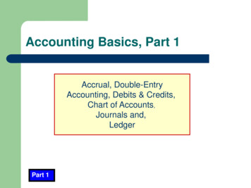
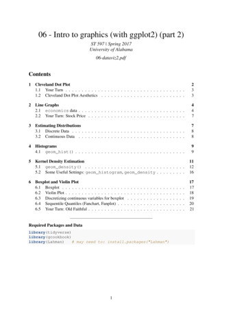
S3.3 FILL BOX LOCATION / SAFETY RELIEF/VENT VALVE CIRCUITTERMINATIONFill boxes and/or vent valve terminations shall be installed above grade, outdoors in anunenclosed, free airflow area. The fill connection shall be located so not to impede means ofegress or the operation of sidewalk cellar entrance doors, including during the delivery processand shall be:a) At least three (3) feet from any door or operable windows.b) At least three (3) feet above grade.c) Shall not be located within ten (10) feet from side to side at the same level or below, fromany air intakes.d) Shall not be located within ten (10) feet from stair wells that go below grade.S3.4 GAS DETECTION SYSTEMSRooms or areas where carbon dioxide storage vessel(s) are located indoors or in enclosed orbelow grade outdoor locations shall be provided with a gas detection and alarm system forgeneral area monitoring that is capable of detecting and notifying building occupants of a CO2gas release. Alarms will be designed to activate a low level pre-alarm at 1.5% concentration ofCO2 and a full high alarm at 3% concentration of CO2 (which is the OSHA & ACGIH 15 minuteand NIOSH 10 minute Short Term Exposure Limit for CO2.) These systems are not designed foremployee personal exposure monitoring. Gas detection systems shall be installed and tested inaccordance with manufactures installation instructions and the following requirements;a) Activation of the gas detection system shall activate an audible alarm within the room orarea in which the carbon dioxide storage vessel is located.b) Audible alarms shall also be placed at the entrance(s) to the room or area where thecarbon dioxide storage vessel and/ or fill box is located to notify anyone who might try toenter the area of a potential problem.S3.5 SIGNAGEWarning signs shall be posted at the entrance to the building, room, enclosure, or enclosed areawhere the container is located. The warning sign shall be at least 8 in (200mm) wide and 6 in(150mm) high. The wording shall be concise and easy to read and the upper portion of the signmust be orange as shown in figure S3.5. The size of the lettering must be as large as possible forthe intended viewing distance and in accordance with jurisdictional requirements. When nojurisdictional requirements exist, the minimum letter height shall be in accordance with NEMAAmerican National Standard for Environmental and Facility Safety Signs (ANSI Z535.2). Thewarning signs shall state the following:19/22
“WARNING – CARBON DIOXIDE GAS. Ventilate the area before entering. A highcarbon dioxide (CO2) gas concentration in this area can cause suffocation.”Figure S3.5a) Additional instruction signage shall be posted outside of the area where the container islocated and such signage shall contain at minimum the following information;Carbon Dioxide Monitors for general area monitoring (not employee personal exposuremonitoring) are provided in this area. These monitors are set to alarm at 15,000ppm(1.5% concentration) for the low level alarm and at 30,000ppm (3% concentration) forhigh level alarm.Low Level Alarm (15,000ppm) – Provide appropriate cross ventilation to thearea. Personnel may enter area for short periods of time (not to exceed 15 minutes at atime) in order to identify and repair potential leaks.High Level Alarm (30,000ppm) – Personnel should evacuate the area and nobody shouldenter the affected area without proper self contained breathing apparatus until the area isadequately ventilated and the concentration of CO2 is reduced below the high alarmlimit.S3.6 VALVES, PIPING, TUBING AND FITTINGSMaterials - Materials selected for valves, piping, tubing, hoses and fittings used in the LCDSVsystem shall meet following requirements:a) Components must be compatible for use with CO2 in the phase, (gas, or liquid) itencounters in the system.b) Components shall be rated for the operational temperatures and pressures encountered inthe applicable circuit of the system.c) Shall be stainless steel, copper, brass, or plastic/polymer materials rated for CO2.20/22
d) Only fittings and connections recommended by the manufacturer shall be used for allhoses, tubes, and piping.e) All valves and fittings used on the LCDSV shall be rated for the maximum allowableworking pressure stamped on the tank.f) All piping, hoses and tubing used in the LCDSV system shall be rated for the workingpressure of the applicable circuit in the system and have a burst pressure rating of at leastfour times the maximum allowable working pressure of the piping, hose or tubing.Relief Valves – Each LCDSV shall have at least one ASME stamped relief valve at or below theMAWP of the tank. The relief valve shall be suitable for the temperatures and flows experiencedduring relief valve operation. The minimum relief valve capacity shall be designated by themanufacturer Additional relief valves that do not require ASME stamps may be added per CGAS-1.3 recommendations. Discharge lines from the relief valves shall be sized in accordance withtables S3.6a & S3.6b Note: due to the design of the LCDSV the discharge line may be smaller indiameter than the relief valve outlet size.Caution: Company’s and or individuals filling or refilling LCDSV’s shall be responsible forutilizing fill equipment that is acceptable to the manufacture to prevent over pressurization of thevessel.Question - What is the ANSI number for CGA S-1.3?Isolation Valves - Each LCDSV shall have an isolation valve installed on the fill line and tankdischarge, or gas supply line in accordance with the following requirements:a) Isolation valves shall be located on the tank or at an accessible point as near to thestorage tank as possible.b) All valves shall be designed or marked to indicate clearly whether it is open or closed.c) All valves shall be capable of being locked or tagged in the closed position for servicing.d) Gas Supply and Liquid CO2 Fill Valves shall be clearly marked for easy identification.Safety Relief/Vent Lines-Safety relief/vent lines shall be as short and straight as possible with acontinuous routing to an unenclosed area outside the building and installed in accordance withthe manufacturer’s instructions. The vent line shall be a continuous run from PRD to outsidevent line discharge fitting, without any splices. These lines shall be free of physical defects suchas cracking or kinking and all connections shall be securely fastened to the LCDSV and the fillbox. The minimum size and length of the lines shall be in accordance with table S3.6a and S3.6b.Fittings or other connections may result in a localized reduction in diameter have been factoredinto the lengths given by the tables S3.6a and S3.6b.21/22
Tank SizeFire Flow RateMaximum length ofMaximum length of ½”(Pounds)Requirements (Pounds per3/8” ID NominalMetallic Tube AllowedMinute)Metallic Tube AllowedLess than 5002.60 maximum80’100’500-7503.85 maximum55’100’Over 750 to5.51 maximum18’100’1000Table S3.6a Minimum LCDSV System Safety Relief/Vent Line Requirements (Metallic)Tank SizeFire Flow RateMaximum length of 3/8 IDMaximum length of ½ ID(Pounds)Requirements (Poundsplastic/polymer materialsplastic/polymer materialsper Minute)Tube AllowedTube AllowedLess than 5002.60 maximum100’100’500-7503.85 maximum100’100’Over 750 to5.51 maximumN/A (See ½” column)100’1000Table S3.6b Minimum LCDSV System Safety Relief/Vent Line Requirements (plastic/polymer)22/22
nb12-0304 nbic part 1 supplement 3 installation of liquid carbon dioxide storage vessels s3.1 scope