Transcription
UNCONTROLLED HARD COPY - - VALID ONLY AT THE TIME OF PRINTING - - 19-Sep-18MS&L ProcedurePRO-4.5-0001-1-02Energy IsolationDocument Owner:Bill KruesiHSSE Manager - Asset Mgmt.Approved By:Owen QuakeBill KruesiPrepared By:Adrian ConnollyANZ Engineering AuthorityHSSE Manager - Asset Mgmt.Control of Work and ContractorManagement AdvisorDocument Status:ApprovedVersion Number:4Approved Date:22-Aug-2018Next Review Due By:22-Aug-2021To review changes refer to the ‘Version Summary’ at the end of this document.Copyright 2018 BP p.l.c. All rights reserved.This document and any data or information generated from its use, are classified, as a minimum, BP Internal.Distribution is intended for BP authorized recipients only. The information contained in this document is subjectto the terms and conditions of the agreement or contract under which this document was supplied to therecipient's organisation. None of the information contained in this document shall be disclosed outside therecipient's own organisation, unless the terms of such agreement or contract expressly allow, or unlessdisclosure is required by law.PRO-4.5-0001-1-02 Energy Isolation – Version 4Page 1 of 29
UNCONTROLLED HARD COPY - - VALID ONLY AT THE TIME OF PRINTING - - 19-Sep-18Contents1.Purpose . 42.Scope . 43.Terms, Definitions and Abbreviations . 44.Roles and Responsibilities . 65.Methodology . 75.1. General . 75.2. Mechanical Isolation . 85.2.1. Positive Isolation95.2.2. Valve Isolation95.2.2.1. Double Block and Bleed95.2.2.2. Single Valve105.2.2.3. Tagged Isolation105.2.2.4. Valve Actuators105.2.2.5. Isolation of other Energy Sources115.2.3. Steps in Isolating and Making Safe115.2.3.1. Identify115.2.3.2. Isolate115.2.3.3. Secure115.2.3.4. Discharge125.2.3.5. Test125.3. Electrical Isolation . 125.3.1. Key Considerations125.3.2. Steps in Isolating and Making Safe125.3.2.1. Identify125.3.2.2. Isolate125.3.2.3. Secure135.3.2.4. Discharge145.3.2.5. Test145.3.3. Interlocks and Automatic Starting of Equipment155.3.4. ‘Try’ Step155.3.5. Cutting of Electrical Cables155.3.6. Opening of Enclosures155.4. Working On or Near Live Electrical Equipment . 165.4.1. Key Considerations165.4.1.1. High Energy Installations165.4.2. Safeguards165.4.2.1. Assessment165.4.2.2. Stand-by Person175.4.2.3. Competency17PRO-4.5-0001-1-02 Energy Isolation – Version 4Page 2 of 29
UNCONTROLLED HARD COPY - - VALID ONLY AT THE TIME OF PRINTING - - 19-Sep-185.4.2.4. Precautions175.4.2.5. Safety Apparel (PPE) for Electrical Work175.4.2.6. Earthing175.4.2.7. Neutral Connections185.4.2.8. Barriers & Insulation Mediums185.4.3. Fault Finding185.4.4. Electrical Test Equipment185.4.4.1. Key Considerations185.4.4.2. Requirements for Electrical Test Equipment195.4.4.3. Prohibited Electrical Testing Equipment195.5. Powered Fixed Equipment Isolation . 205.6. Vehicles and Portable Equipment . 205.7. Application of Isolation . 205.7.1. Area Isolation215.7.2. Vessel Isolation (not for confined space entry)215.7.3. Confined Space Entry Isolation (General)215.7.4. Confined Space Entry Isolation (Tanks)215.7.5. Confined Space Entry Isolation (valve chambers and tank turrets)225.7.6. Confined Space Entry Isolation (vehicles)225.8. Removal of Locks and Tags (De-isolation and Commissioning) . 225.9. Commissioning . 235.10. LOTO Equipment . 236.Verification . 237.Associated Documents . 238.External References . 249.Version Summary . 24Annex A -Example LOTO Plan25Annex B -Typical Valve Isolation Integrity Tests26Annex C -Tagging29List of Tables, Diagrams and FiguresTable 1: Terms, Definitions and Abbreviations . 4Table 2: Roles and Responsibilities. 6Figure 1: Single Valve Isolation with Lock and Tag. 10Figure 2: Electrical Circuit Breaker with Multiple Lock hasp, Single Lock and Tag . 14Figure 3: Neon Test Pencils - Prohibited for Use. 19Table 3: Required References . 23Table 4: Document Version Summary . 24PRO-4.5-0001-1-02 Energy Isolation – Version 4Page 3 of 29
UNCONTROLLED HARD COPY - - VALID ONLY AT THE TIME OF PRINTING - - 19-Sep-181.PurposeWhenever BP conducts construction, maintenance, demolition, remediation and other similar work thatare typical of our industry, there is the potential for harm to people and the environment and for damageto equipment. This document provides requirements for the isolation of energy systems in support ofPRO 4.5-0001-0-01 Control of Work and WPCG-PRO-01 Work Authorisation. Energy Isolation is a keycomponent of the system of work that allows tasks to be completed safely and without unplanned loss ofcontainment with the potential to cause environmental damage or to damage a plant or equipment.This procedure sets out a required approach to isolation of energy systems in accordance with BP’sGolden Rules of Safely, the requirements of GDP 4.5-0001 Control of Work, Annex 1 and OMS GroupEssentials 3.2.1 and 4.5.1.This procedure specifically details the requirements of the following documents: 2.Group Defined Practice (GDP); GDP 4.5-0001 2016 Control of WorkScopeThe requirement specified in this procedure applies equally to BP employees, contractors and visitorsengaged in the ANZ MS&L business.Specific sites, areas and activities may have more detailed OMS requirements and where these exist therequirements will be specified in local procedures, safe work instructions, manuals, handbooks orspecific standards.3.Terms, Definitions and AbbreviationsTable 1: Terms, Definitions and AbbreviationsClose ProximityCompetentLocations on installations, where deliberate, accidental or inadvertentcontact with electrical equipment is possible, either direct or indirectthrough tools, long objects, drills, cutting blades, etc. For the purposes ofthis practice ‘close proximity’ is taken to be 500mm.An individual in a Control of Work role who can demonstrate that theyhave professional or technical training, knowledge, actual experience,qualifications and ability to enable them to:a) Perform duties at the level of responsibility allocated tothem;b) Understand any potential hazards related to work (orequipment) under consideration;c) Recognise any technical defects or omissions in a task (orequipment) and the adverse implications for health andsafety caused by the hazard(s) and / or omission(s); andPRO-4.5-0001-1-02 Energy Isolation – Version 4Page 4 of 29
UNCONTROLLED HARD COPY - - VALID ONLY AT THE TIME OF PRINTING - - 19-Sep-18d) Be able to specify corrective action(s) to mitigate theComplex isolationsDe-energised (electrical)Electrical WorkerExtra Low Voltage (ELV)Fault Finding (electrical)High Energy Electrical SystemIsolated (electrical)Isolation PlanIsolation RegisterIsolator (electrical)Lock-outLOTOhazards.These may include, but are not limited to, work requiring isolation of dualenergy sources, multiple sources of energy requiring isolation, isolationsrequired by multiple trades or organisations, and isolations required forconfined space entry. Consider all sources, not just electrical, whenassessing the complexity of isolations required to safely execute thework.Disconnected from all sources of supply but not necessarily isolated,earthed or out of commission.Person or persons engaged in the installation, maintenance, repair andtesting of electrical equipment.Voltage not exceeding 50 V AC or 120 V ripple-free DCThe process of taking measurements or carrying out tests on electricalinstallations and equipment to locate faults or prove operability. It mayalso include the process of applying testing instruments or devices tovarious parts of the electrical installation.Electrical systems rated at 800A or where the fault current at the point ofthe installation exceeds 2,000A.The state of equipment when disconnected from all sources of supply bybreaks of a length appropriate to the voltage and the insulating medium.A form to specify and record Lockout points for more complex plantisolations. Also referred to as a LOTO Plan.Centralised site’s register of all current plant isolations in place at the site.Also referred to as a LOTO Register.A device which for reasons of safety, provides in the open position,breaks appropriate to the voltage and the insulating medium.The use of locks and / or locking devices (e.g. chains and locks, clasps andlocks) to ensure energy sources and energy control devices such aselectrical breakers and valves are secured in a safe position.Lock Out Tag OutLow VoltageA term applied to an object when a difference of potential exists betweenconductors or would exist between it and earth under normal conditionsof operation.Exceeding extra-low voltage, but not exceeding 1,000 V AC or 1,500 V DCMCCMotor Control CentreOn or near (electrical)A situation where an electrical worker is working on or near exposedenergized conductors or live conductive parts and there is a reasonablepossibility that the electrical worker’s body, or any conducting mediumthe electrical worker may be carrying or touching during the course of thework, may come closer to the exposed energized conductors or liveconductive parts than 500 mm. The term ‘on or near exposed energizedconductors or live conductive parts’ does not apply if the uninsulated andenergised part is safely and securely shielded by design, or segregatedand protected with barricades or insulated shrouding or insulatingmaterial to prevent inadvertent or direct contact.Programmable Logic Controller that controls the operation of equipmentvia software coding.Positive isolation is defined as either:a) Spool removal - removal of a pipework section or spoolpiece and blanking the live end, also called ‘air gapping’.b) Blind isolation - insertion between flanges of a blind (spade);the swinging closed of a spectacle blind (plate); orLive (energised)PLCPositive isolationPRO-4.5-0001-1-02 Energy Isolation – Version 4Page 5 of 29
UNCONTROLLED HARD COPY - - VALID ONLY AT THE TIME OF PRINTING - - 19-Sep-18Site RepresentativeTag-outTesting (of LOTO)4.replacement of a spacer (slip-ring) with a line blind (spade).The Site Representative is a person with responsibility for the overallsafety on a site, who has the ability to stop work at any time.The attachment of prominent warning tags to locks and / or lockingdevices that forbids the operation of energy control device and associatedequipment and communicates the reason for lock-out. It bears the nameof the person who applied the tag and the date the tag was applied. Ifmore than one group is working on the same item (including differenttrades) each person from each group should have an individual tag but asa minimum one responsible person from each group shall sign and datea “DANGER, DO NOT START”, or equivalent, tag. See Annex C The act of confirmation that plant and equipment is isolated and deenergised by checking the integrity of the local energy control devices(e.g. valve, isolator), and that plant and equipment is de-energised (e.g.by trying to start equipment or confirming de-pressurisation / drain down.It is critical that all bleeds, vents and drains are checked to be free fromblockage prior to testing.Roles and ResponsibilitiesThe roles and responsibilities associated with this procedure are listed in the following table.Table 2: Roles and ResponsibilitiesPlannerPermit OfficerPermit ReceiverSite RepresentativeThe person responsible for planning the Energy Isolation shall ensure thatthe Permit Receiver is communicated the requirements of this procedureas part of the planning process prior to work. The planner role is oftennot a dedicated role and may be fulfilled by Project Manager, ProjectEngineer, Project Delivery Lead, Site Manager, Retail RegionalMaintenance Coordinator, etc.The Permit Officer shall ensure the requirements of this procedure andconditions of the risk assessment for the task and any associated workpermits or work clearances (as applicable) are followed. WPCG-PRO-01Work Authorisation documents the responsibilities of the Permit Officerfor all work permits associated with Energy Isolation. The Permit Officershall not be the same person as the Permit Receiver.WPCG-PRO-01 Work Authorisation documents the responsibilities of thePermit Receiver for all Work Permits associated with Energy Isolation.The Site Representative shall be the site manager or delegate, or if thesite is unmanned it may be the Permit Officer. The Site Representative isresponsible for the overall safety of the site. The Site Representative shallbe aware of all planned operations of the site that may interact with thework. Therefore no work shall be undertaken before the SiteRepresentative countersigns the permit.The Site Representative may stop or defer work at any time.PRO-4.5-0001-1-02 Energy Isolation – Version 4Page 6 of 29
UNCONTROLLED HARD COPY - - VALID ONLY AT THE TIME OF PRINTING - - 19-Sep-185.Methodology5.1.GeneralWhere a Work Permit is issued, isolations shall be recorded on the Work Permit or Lock out Tag out(LOTO) Plan. Where a WPCG Work Clearance is issued, the isolations shall be recorded on a LOTO Planor other associated document for the work such the safe work procedure or risk assessment, as aminimum. Once isolations have been performed, they shall be checked by the Permit Receiver beforecommencing work.Locks and tags shall be issued and recorded when plant is to be isolated. The same locks and tags shallbe recovered and checked off when the plant is to be re-commissioned. For complex isolations (asidentified during the risk assessment for the task) a LOTO Plan shall be prepared, documenting where alllocks and tags are to be placed. These should then be checked off the LOTO plan as they are placed andagain when they are removed at the end of the work - refer Annex A - for a LOTO plan.Complex isolations may include, but is not limited to, work requiring isolation of dual energy sources,multiple sources of energy requiring isolation, isolations required by multiple trades or organisations,and isolations required for confined space entry. Consider all sources, not just electrical, when assessingthe complexity of isolations required to safely execute the work. Complex isolations should documentthe sequence of isolation/de-isolation in the LOTO PlanIf more than one work group is required to lock out equipment (including different trades), a minimum ofone responsible person from each group shall place their own lock on the energy isolating device using amulti-lock hasp. The lock shall be tagged with the name of the person(s) who applied the lock and whoholds the key.Equipment shall be clearly and unambiguously identified. Where a credible risk is present there shouldbe designation of which equipment will be identified in the field as de-energised, and which equipmentwill be identified as energised.The general process for LOTO work is as follows: Prior to work being undertaken under the isolation:a) Identify all potential energy sources or situations where a release of energy or product mayoccur.b) Identify all isolation points. Competent persons shall agree to the method of isolation.These can be a valve, blind flange, circuit breaker, switch or fitting etc.c) Include the isolation requirements on any work permits, work clearances, or procedure.Identify and record isolations that are common to more than one permit, work clearance orprocedure.PRO-4.5-0001-1-02 Energy Isolation – Version 4Page 7 of 29
UNCONTROLLED HARD COPY - - VALID ONLY AT THE TIME OF PRINTING - - 19-Sep-18d) Obtain approval from the Site Representative to place tags and isolations and inform allwho may be affected. Locks and tags shall be able to withstand environmental conditions.e) Place and install isolations as close to the worksite as possible to assist in security and easeof monitoring.f)Competent persons shall agree to the method by which stored energy will be discharged. Aresponsible, competent person shall safely discharge stored energy, e.g. drain anddepressurize and / or discharge electrical or other sources of energy. It is critical that allbleeds, vents and drains are checked to be free from blockage during discharge of storedenergy, and prior to testing the isolation is effective.g) Test to be conducted to confirm that equipment is isolated and that plant / equipment is deenergized / depressurized and / or cannot be started. Whilst work is being undertaken under the isolationh) Regular monitoring and testing of isolations. Monitoring and testing intervals shall bestipulated in the work permit, risk assessment, or procedure for the task. If there is apossibility of isolations integrity being affected during the work, verifying their integrity by:1. Testing isolations regularly.2. Monitoring isolations regularly. When work is complete:i)Check that all people involved in the work have finished.j)Obtain approval from the Site Representative to remove locks, tags and isolations. Informall people who have been affected.k) Check system integrity.l)Ensure all equipment and personnel are clear.m) Drain and depressurize and / or de-energise and remove all blinds etc. and reinstate allbroken connections to same order as before application of LOTO. Care shall be taken whenremoving these positive isolation devices as stored energy may develop between it and thenext isolation valve / point on the energized side of the plant.n) "Unlock” lockout system, remove tags and re-commission.o) Test.p) Check all Locks and Tags back into the site LOTO system and sign off the LOTO Plan.5.2.Mechanical IsolationThe method of isolation and discharge of stored energy shall be approved by the Permit Officer (toapprove the work as safe to do under the isolation) and Site Representative (to approve any businessoperational impact) and be executed by the responsible person(s). Isolation of the highest quality andsecurity which is reasonably practicable shall always be used.PRO-4.5-0001-1-02 Energy Isolation – Version 4Page 8 of 29
UNCONTROLLED HARD COPY - - VALID ONLY AT THE TIME OF PRINTING - - 19-Sep-185.2.1. Positive IsolationPositive Isolation is regarded as the most secure method and shall be considered in the development ofall LOTO Plans.Positive isolation is defined as:a) Spool removal - removal of a pipework section or spool piece and blanking the live end,also called ‘air gapping’.b) Blind isolation - insertion between flanges of a blind (spade); the swinging closed of aspectacle blind (plate); or replacement of a spacer (slip-ring) with a line blind (spade).Positive isolation by spool removal or air gapping shall be considered as the minimum sole means ofisolation for confined space entry - exception for the use of line rated blind only as authorised by theEngineering Authority for the business - refer section 5.8. When a spool or valve is removed, (airgapped) the ‘live’ pipework side shall be fitted with a blank flange. In most circumstances the isolatedequipment (vessel or pipe-work) flange should be left open to allow the vessel or pipe-work to "breathe".Positive isolation by spool removal shall be achieved for any isolation lasting longer than one month.Where spool removal cannot be achieved, isolation by a valve and line rated spade provides the nexthighest quality and security. The valve shall be locked and the spade inserted for that particularisolation. The valve and spade shall be tagged in their secure position to prevent inadvertent operationand removal.Spectacle blinds, blank flanges, bolting, and gaskets shall, as a minimum, be adequate thickness for theline rating. New, correctly rated gaskets shall be installed and all correctly sized bolts shall be installedand tightened.Isolation by valve and line rated spade shall be considered as the minimum sole means of isolation forhot work, and shall only be acceptable for isolations of less than one month duration. These conditionsshall form part of a risk assessment, which shall form part of the Work Permit and be kept with thepermits.5.2.2. Valve Isolation5.2.2.1. Double Block and BleedDouble block and bleed is the most secure form of valve isolation, but should only be used if the valve(s)can provide a reliable seal under the particular conditions of service. The main valve shall be locked andtagged closed and the bleed shall be wired and tagged open to prevent inadvertent operation.Double block and bleed valve isolations may be considered as the minimum sole means of isolation forroutine short duration cold work for moderate and high pressures. This type of isolation shall only beused if the duration of the work is short (less than 4 hours) and the immediate work site shall not be leftPRO-4.5-0001-1-02 Energy Isolation – Version 4Page 9 of 29
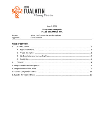
UNCONTROLLED HARD COPY - - VALID ONLY AT THE TIME OF PRINTING - - 19-Sep-18unattended. These conditions shall form part of a mandatory risk assessment which shall form part ofthe Work Permit and be kept with the permit.5.2.2.2.Single ValveIn single valve isolations the integrity of the isolation is critically dependent upon the reliability of the sealunder the particular conditions of service and the security of the single valve operating stem.Isolation against a tested single valve may be used for the purpose of swinging a spectacle blind,inserting a line rated spade or fitting a blind flange to achieve higher integrity isolation.Single valve isolations may be considered as the sole means of isolation for routine, short duration, coldwork where pressures on the active side are less than 200 kPa g. The duration of work shall be short (lessthan 4 hours) and the immediate work site shall not be left unattended. These conditions shall form partof the risk assessment which shall form part of the Work Permit and be kept with the permit.Figure 1: Single Valve Isolation with Lock and Tag5.2.2.3.Tagged IsolationIsolation by tagging out with tags only is not considered sufficient and may only be used in exceptionalcircumstances where inadvertent operation will not compromise HSSE. Tagged isolation shall requireapproval by the Permit Officer and Site Representative.5.2.2.4.Valve ActuatorsWhen used for isolation:a) Manually operated valves shall be locked and tagged to prevent unauthorized orinadvertent operation.b) Electrically actuated valves shall have the power supply positively isolated and any manualoverride shall be manually locked.PRO-4.5-0001-1-02 Energy Isolation – Version 4Page 10 of 29
UNCONTROLLED HARD COPY - - VALID ONLY AT THE TIME OF PRINTING - - 19-Sep-18c) Pneumatic and hydraulic operated valves which fail closed shall have the control linesisolated and physically disconnected. Pneumatic and hydraulic operated valves which failopen or fail as is shall not be used for isolation purposes.5.2.2.5.Isolation of other Energy SourcesOther energy sources can include heat, gas, steam, gravity and pressure. These shall be isolated by aphysical break which is identified by a tag and secured by a lock or an equivalent mechanical means thatcannot be neutralized without the use of tools. Open ends shall be blanked or capped.Persons performing the work shall test the operation of equipment before work commences to ensureeffective isolation.5.2.3. Steps in Isolating and Making SafeThe following key steps shall be applied when making safe mechanical installations.a) Identifyb) Isolatec) Secured) Dischargee) Test5.2.3.1. IdentifyThe equipment to be worked on and all isolation points shall be clearly identified. For ComplexIsolations, a copy of the plant P&ID’s shall be marked showing which items are isolated and attached tothe LOTO plan.5.2.3.2.IsolateThe equipment to be worked on shall be isolated from all sources of energy by the highest method ofisolation as reasonably practical and meeting the minimum isolation requirements as per sections 5.3.1and 5.3.2. Consideration should also be given to locking out and tagging any originating sources ofenergy (e.g. pump motor circuit breakers) of the system.5.2.3.3.SecureAll isolation points shall be locked out to ensure energy control devices, such as valves, are secured in asafe position from inadvertent operation.Appropriate warning tags shall be placed at all isolation points, which forbids the operation of the energycontrol device and associated equipment, communicates the reason for lock-out, the name of the personwho applied the tag and the date the tag was applied. Consideration should also be given to locking outPRO-4.5-0001-1-02 Energy Isolation – Version 4Page 11 of 29
UNCONTROLLED HARD COPY - - VALID ONLY AT THE TIME OF PRINTING - - 19-Sep-18and tagging any originating sources of energy (e.g. pump motor circuit breakers) of the system. SeeAnnex C -5.2.3.4.DischargeOnce isolations have been made, all stored energy as is reasonable practicable shall be discharged. Priorto breaking containment of a pipeline or piece of equipment (e.g. filter vessel), it shall be de-pressurisedto atmospheric pressure by means of a vent or drain to atmosphere. Any product or contaminated watershall be captured. Product or contaminated water shall not be allowed to drain to ground or be directedinto open drains. It is critical that all bleeds, vents and drains are checked to be free from blockage priorto testing.5.2.3.5.TestThe energy control devices (e.g. valves,) as well as plant and equipment which is isolated, shall be testedprior to conducting work to prove effective energy isolation5.3.Electrical Isolation5.3.1. Key ConsiderationsElectrical equipment shall be considered to be energised (i.e. live) until proven de-energised.5.3.2. Steps in Isolating and Making SafeThe following key steps shall be applied when making safe electrical installations.a) Identifyb) Isolatec) Secured) Dischargee) Test5.3.2.1.IdentifyElectrical equipment to be worked on and the appropriate point of supply shall be clearly identified.Identification of equipment should include labelling that is both consistent and clear at the equipment tobe worked on and all points of possible isolation, e.g. control isolator and main point of supply.5.3.2.2.IsolateThe electrical equipment to be worked on shall be isolated from all sources of supply (e.g. mains,generator, battery or solar) either by opening switches, removing fuses or switching circuit breakers.Where isolation is effected at a removable or rack-out circuit breaker or combined fuse switch or aremovable fuse the device should be racked out or removed to provide a visible break for isolationverification.PRO-4.5-0001-1-02 Energy Isolation – Version 4Page 12 of 29
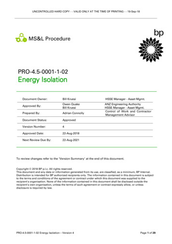
UNCONTROLLED HARD COPY - - VALID ONLY AT THE TIME OF PRINTING - - 19-Sep-18Where isolation is provided by the removal of fuses in a distribution board or motor starter the followingshall apply:a) Removed fuses shall not be stored in the same panel as the fuse holder.b) Fuses shall be tagged and stored in a secure location during the period in which equipmentis isolated.c) Blank or empty fuse cartridges, preferably painted yellow and tagged ‘for isolationpurposes’ shall be inserted into the fuse holder to prevent inadvertent contact with exposedconductors and to clearly identify that equipment is under isolation.Confirmation shall be made that all required isolations are in place. For complex isolations, thisconfirmation may be by a nominated second person if deemed necessary to manage the risk of incorrectisolation.5.3.2.3.Securea) TaggingTags shall be placed at all points of switching, isolation or disconnection. Such tags shall beclearly understandable and signed and dated by the person placing the tag or by the supervisorin charge of the work party. Identification labels should also include warnings for any abnormalhazards, e.g. multiple points of supply, etc. See
5.7.2. Vessel Isolation (not for confined space entry) 21 5.7.3. Confined Space Entry Isolation (General) 21 5.7.4. Confined Space Entry Isolation (Tanks) 21 5.7.5. Confined Space Entry Isolation (valve chambers and tank turrets) 22 5.7.6. Confined Space Entry Isolation (vehicles) 22 5.8. Removal of Locks and Tags (De-isolation and .