Transcription
INTGRATING PROCESSING IN-MEMORY (PIM) TECHNOLOGY INTO GENERALPURPOSE GRAPHICS PROCESSING UNITS (GPGPU) FOR ENERGY EFFICIENTCOMPUTINGA ThesisPresented tothe Faculty of the Department of Electrical EngineeringUniversity of HoustonIn Partial Fulfillmentof the Requirements for the DegreeMaster of Sciencein Electrical EngineeringbyParaag Ashok Kumar MegharajAugust 2017
INTGRATING PROCESSING IN-MEMORY (PIM) TECHNOLOGY INTO GENERALPURPOSE GRAPHICS PROCESSING UNITS (GPGPU) FOR ENERGY EFFICIENTCOMPUTINGParaag Ashok Kumar MegharajApproved:Chair of the CommitteeDr. Xin Fu, Assistant Professor,Electrical and Computer EngineeringCommittee Members:Dr. Jinghong Chen,Associate Professor,Electrical and Computer EngineeringDr. Xuqing Wu, Assistant Professor,Information and LogisticsTechnologyDr. Suresh K. Khator, Associate Dean,Cullen College of EngineeringDr. Badri Roysam, Professor andChair of Dept. in Electrical andComputer Engineering
AcknowledgementsI would like to thank my advisor, Dr. Xin Fu, for providing me an opportunity to studyunder her guidance and encouragement through my graduate study at University ofHouston.I would like to thank Dr. Jinghong Chen and Dr. Xuqing Wu for serving on my thesiscommittee.Besides, I want to thank my friend, Chenhao Xie, for helping me out and discussing indetail all the problems during the research.I would also like to thank my parents for their support and encouragement to pursue amaster’s degree.Finally, I want to thank my girlfriend, Shalini Singh, for all her love and support.iv
INTEGRATING PROCESSING IN-MEMORY (PIM) TECHNOLOGY INTOGENERAL PURPOSE GRAPHICS PROCESSING UNIT (GPGPU) FOR ENERGYEFFICIENT COMPUTINGAn Abstractof aThesisPresented tothe Faculty of the Department of Electrical and Computer EngineeringUniversity of HoustonIn Partial Fulfillmentof the Requirements for the DegreeMaster of Sciencein Electrical EngineeringbyParaag Ashok Kumar MegharajAugust 2017v
AbstractProcessing-in-memory (PIM) offers a viable solution to overcome the memory wallcrisis that has been plaguing memory system for decades. Due to advancements in 3Dstacking technology in recent years, PIM provides an opportunity to reduce both energyand data movement overheads, which are the primary concerns in present computerarchitecture community. General purpose GPU (GPGPU) systems, with most of itsemerging applications data intensive, require large volume of data to be transferred at fastpace to keep the computations in processing units running, thereby putting an enormouspressure on the memory systems.To explore the potential of PIM technology in solving the memory wall problem,in this research, we integrate PIM technology with GPGPU systems and develop amechanism that dynamically identifies and offloads candidate thread blocks to PIM cores.Our offloading mechanism shows significant performance improvement (30% by averageand up to 2.1x) as compared to the baseline GPGPU system without block offloading.vi
Table of ContentsAcknowledgments .ivAbstract . viTable of Contents . viiList of Figures xList of Tables . xii1 Introduction . 12 Motivation . 43 Background . 63.1 General Purpose Graphics Processing Unit . 63.2 3D-stacked DRAM .63.3 Processing In-memory . 73.4 Hybrid Memory Cube . 74 Modelling PIM enabled GPGPU . 94.1 GPGPU Simulator . 94.1.1 Background on GPGPU-sim 94.1.2 GPGPU-sim memory organization . 94.2 Stacked Memory Organization 11vii
4.2.1 Integrate stacked memory with GPGPU . 144.2.2 Off-chip links 164.3 Processing In-Memory . 175 Block Offloading Mechanism . 205.1 Identifying block offload candidate . 205.2 Block offload limitations . 215.3 Block offload aggressiveness . 225.4 Implementation Details . 235.4.1 GPGPU pipeline with block offloading 235.5 Simulation setup and evaluation . 275.5.1 Methodology 275.5.2 Performance results . 305.5.3 GPU resource utilization . 335.5.4 Stalls and bottleneck analysis . 335.5.5 Performance dependence on internal/external bandwidth . 355.5.6 Energy consumption results . 376 Related work . 396.1 Current DDRx systems 39viii
6.2 2D Processing in-memory 407 Conclusion 428 Future work . 43References . 44ix
List of FiguresFigure 1High level diagram of integration of Processing in-Memory3(PIM) with General Purpose Graphics Processing Unit (GPGPU)Figure 2Execution time of different thread blocks running on GPU core5Figure 33D stacked memory concept with logic layer and TSVinterconnects6Figure 4Overall GPU architecture modeled by GPGPU-sim10Figure 5GPGPU-Sim memory partition component11Figure 6HMC memory and in-memory processing logic organization12Figure 7GPGPU Sim memory architecture overview14Figure 8HMC memory architecture implemented in GPGPU-sim15Figure 9Detailed GPU Shader core18Figure 10Detailed PIM logic core18Figure 11Block diagram of our offloading system and its interaction withGPU pipeline23Figure 12Block execution times for different blocks running on same core24Figure 13Block execution monitor senario-225Figure 14Performance speed up comparisons32Figure 15Average block execution time for all the GPU cores with andwithout block offloading34Figure 16Stalls due to warps waiting for data from memory in blockoffloading to PIM35Figure 17Comparison in performance of block offloading mechanism with 36different combination of internal and external memorybandwidthsx
Figure 18Energy consumption in PIM enabled GPGPU with Blockoffloading monitor37Figure 19Energy consumption in PIM enabled GPGPU37xi
List of TablesTable 1HMC configuration13Table 2Configuration setup27Table 3Applications used28xii
1 IntroductionIn recent years, main memory systems have become well known to be the criticalbottlenecks for performance in majority of modern day general purpose GPUapplications. This is mainly because memory systems haven’t been unable to keep pacewith the rapid improvements in GPU processing cores. In conjunction with incrediblecapabilities in handling different kinds of complex computations at high instructionsper cycle, processing cores have also developed good energy efficiency. These rapiddevelopments can be credited to the advent of multi-core and multi-threaded systemarchitectures, aggressive pipelines designs and various scheduling techniques.Improvement in bandwidth, latency and energy consumption of off-chip memorysystem have not kept in pace with these advances [7, 8]. Hence, the memory systemoften becomes a bottleneck and accounts for significant system level energyconsumption [10].There are two major problems that today’s GPU systems encounter frequently: Insufficient memory bandwidth to meet the demands of GPU multi-core processorchips - This insufficiency gets adverse as the number of cores on the chip increases.This is the primary reason why memory bandwidth issue is very frequently (almostevery time by programmers) experienced in GPU systems as their architecturecommands thousands of cores, all running in parallel. Power consumption - As systems expand in capabilities and multiple systemscollaborating with each other to speed up application, power consumption by thesesystems become equally important factors in deciding its reliability.1
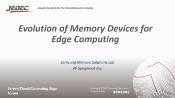
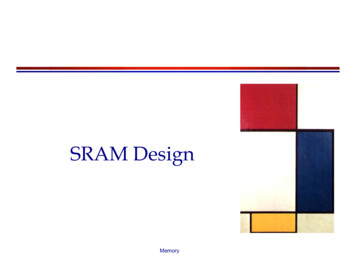
With the emergence of new 3D stacked memory technology, problem ofbottlenecks due to insufficient memory bandwidth can be solved effectively [33]. Thisis possible due to the high memory bandwidth, low memory access latency and lowenergy consumption in this technology. However the most important feature ofstacking technology is that it enables close coupling of processing logic and thememory, hence processing in-memory. This is a very major advantage of thistechnology making it very promising for optimizing a large range of applications [34,35]. Coupling logic very close to stacked memory is important because it enables us tocompletely utilize high bandwidth from stacked memory which otherwise would belimited to the bandwidth offered by the off chip links.To further validate effectiveness of this technology, we explore the industryadvancements in this technology which is very evident with Samsung Electronics andSAP co-developing in-memory technology. Hybrid Memory Cubes (HMC) 2.0introduced by Micron which exploits stacking technology and re-architects the DRAMbanks to achieve better timing and energy efficiency at a much smaller area footprint[16, 17]. A JEDEC standard for high performance applications, High BandwidthMemory (HBM) [12]. In addition a number of academic publications have alsoexplored stacked DRAM on logic dies [13, 14, 15].Hence we believe that enabling general purpose graphics processing units withprocessing in-memory technology can speed up performances and increase energyefficiency [1, 36]. Figure 1 shows a high level diagram of integrating processing inmemory (PIM) technology with GPGPU system. This system consists of host GPGPU2
connected with stacks of DRAM memory and PIM logic cores using off chip seriallinks. There can be one or more number of processing cores with stacked memory.Figure 1: High level diagram of integration of Processing in-Memory (PIM) with General PurposeGraphics Processing Unit (GPGPU)Offloading parts of execution workload from GPGPU to PIM can speed upperformance and also ease bottlenecks due to memory access traffic on the off chiplinks.In this research work, we want to explore and examine the potential of Processingin-Memory (PIM) technology. Through this research work we intend to:i.Model PIM enabled GPGPU and develop a technique that dynamically identifiesand offloads parts of execution to a PIM cores.ii.Effectively utilize the stacked memory resources i.e. high internal memorybandwidth, in a fast and energy efficient way.iii.Evaluate the effectiveness of this technology with GPGPU system and investigatehow PIM will impact the energy consumption on GPGPU workloads.3
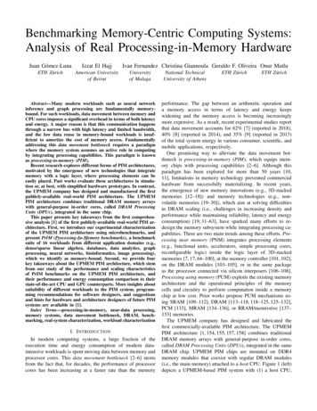
2. MotivationThe major challenge in working with PIM technology is deciding which part of theworkload must be offloaded to the PIM cores. Most prior research in this areademonstrate that memory intensive instructions are the most favorable candidates foroffload [1, 6, 37]. These candidates could be identified with help from the programmerwho will specify, to best of their knowledge, which part of the code is memory intensiveand should be run on PIM cores [21, 36, 38]. However, this is not a very good techniqueto identify candidates for offload, because here the programmer must be well versedwith the underlying implementation and memory interaction. Also, with this technique,offloading becomes only as good as the programmer. Another technique to determinecandidates for offload could be by combined efforts from the compiler and theunderlying hardware [6, 37].These methods only identify memory intensive parts of the code for offload.However, offloading parts of code (known as a kernel in GPU terminology) to the PIMdoes not always result in optimal performance benefit. When an instruction is beingexecuted on GPU cores, different threads process the same instruction but on differentdata elements (data parallelism). Here we observe that even if a memory intensiveinstruction is being executed, different thread blocks (group of threads running on aGPU cores) have different memory intensities. Common examples of applicationconstantly running on imbalanced workloads are graph computing applications [39].An example of this is described in figure 2.4
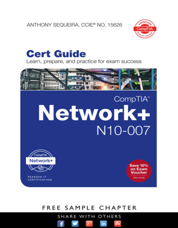
Figure 2, gives a distribution of thread blocks, Cooperative Thread Arrays (CTA)in CUDA terminology, being executed on a GPGPU core at different instances withtheir average execution times. In the figure, there are six blocks running on a coresimultaneously at six different instances. We can observe that block execution time ofdifferent thread blocks can be highly imbalanced with fastest thread blocks executingat an average of 700 cycles and slowest ones executing in around 4000 cycles.40003500clock cycle3000Block 12500Block 22000Block 31500Block 41000Block 5500Block 60123456Different instances a GPGPU core running six different blocksFigure 2: Execution time of different thread blocks running on GPU coreBy analyzing execution time of each thread block running on every GPGPU corewe can determine the ones running slower which may be offloaded to the PIM cores.Offloading these blocks will not only speedup the performance but also ensure moreefficient resource utilization across both GPU and PIM cores.5
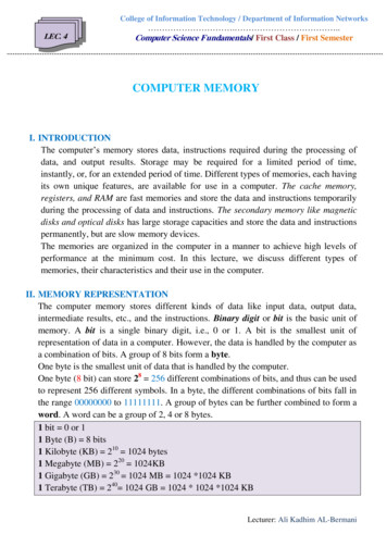
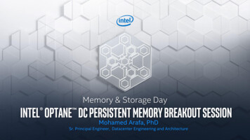
3. Background3.1 General Purpose Graphics Processing Unit (GPGPU)GPGPU units are use of GPU, which are typically used for computer graphicsprocessing, to perform complex computations traditionally handled by a CentralProcessing Unit (CPU). Modern graphics architectures have become very flexible toprogram as well as very powerful with high computation speed, increased precisionand rapidly expanding programmability of hardware. These features have made GPUan attractive platform for general purpose computing [4].3.2 3D-stacked DRAM memoryFigure 3: 3D stacked memory concept with logic layer and TSV interconnects3D stacking brings the primary advantage of increased memory density overconventional 2D designs by stacking multiple DRAM dies atop of each other on asingle chip. Stacked memory technology promises memory access with low latency,high bandwidth and lower power consumption [28]. Another advantage with stackingtechnology is that the base die can be utilized to integrate controllers and high speedsignaling circuits hence bringing them much closer to memory [2]. 3D stacking has6
been possible in recent years only due to development of Though Silicon-Via (TSV).TSV technology facilitates vertical interconnects between the stacked DRAM dieshence providing a shortest possible way to connect two DRAM dies [40, 41]. TSVbased vertical interconnects have proven to have very low latency, high bandwidth andenergy efficient data transfer between dies in a package.3.3 Processing in-MemoryIn Processing in-Memory (PIM) technology, computational/logic units can beplaced very close to the memory to achieve faster memory access. Integratingprocessing logic with stacked DRAM memory can help utilize the high internalmemory bandwidth. PIM has been possible only due to inventions in 3D stackingtechnology [3] as discussed before. Stacking technology has enabled to incorporatememory and logic very close to each other, hence providing dense and fast memoryinteractions. In our work, we consider Hybrid Memory Cube (HMC) [42] as ourprimary reference platform for implementation and integration of PIM with GPGPU.3.4 Hybrid Memory CubeHybrid Memory Cube (HMC) is a concrete example of current advances in diestacking technologies. HMC is a closed bank memory architecture with four or eightDRAM dies and one logic die (at the base) stacked together using TSV technology.This design improves bandwidth, latency and energy characteristics — withoutchanging the high-volume DRAM design currently used in various systems. HMCstorage paradigm is developed by a consortium of memory industry manufacturers andconsumers. The Hybrid Memory Cube Consortium (HMCC) is backed by several major7
technology companies including Samsung, Micron Technology, Open-Silicon, ARM,Altera, and Xilinx.The logic layer in HMC contains several memory controllers which communicatewith the memory storage elements in the DRAM dies using TSV interconnects. WithinHMC, memory is organized into vaults. Each vault is functionally and operationallyindependent. Each vault has a memory controller (called a vault controller) present inthe logic base that manages all memory reference operations within that vault. Eachvault controller can determine its own timing requirements. Refresh operations arecontrolled by the vault controller, eliminating this function from the host memorycontroller. A vault can be thought of roughly equivalent to a traditional DDRx channelsince it contains a controller and several independent banks of memory that all share abi-directional data bus.Capacity is a clear benefit of HMC architecture. Currently, 4 DRAM die stackshave been demonstrated by Micron and future plans to stack 8 dies has been mentioned.Furthermore, multiple HMC cubes can be chained together to further increase thecapacity. However, this will be limited by latency and loading considerations [9].8
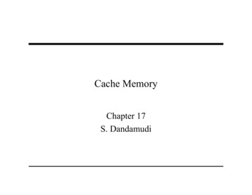
4 Modelling PIM enabled GPGPU4.1 GPGPU SimulatorIn this chapter we discuss, in detail, about the GPGPU simulator system, memoryhierarchy, and its interactions with the GPGPU cores.4.1.1 Background on GPGPU-simThe general purpose computations on GPU is modeled using a widely usedGPGPU-sim 3.x [19], a cycle level GPU performance simulator to model GPUcomputing. GPGPU-sim 3.2.0 is the latest version of GPGPU-sim. This simulatormodels GPU microarchitectures similar to those in NVIDIA GeForce 8x, 9x and Fermiseries. The intension of GPGPU-sim is to provide a substrate for architecture researchrather than to implement an exact model of any particular commercial GPU, hencemaking it central to this research. The GPU modeled by GPGPU-sim is composed ofSingle Instruction Multiple Thread (SIMT) cores connected via an on-chip connectionnetwork to memory partition units that interface to graphics GDDR DRAM. Wesimulate all the benchmarks with default GPGPU-sim’s configuration (for steamingmultiprocessor, shader processors, and caches) that closely models a NVIDIA GTX480 chipset.4.1.2 GPGPU-sim memory organizationThe following figure 4 gives a top level view of the organization used by GPGPUsim. The simulator uses a GDDR DRAM. Each DRAM is interfaced with one memory9
partition unit. The memory system is modelled by a set of memory partitions whicheffectively function as memory controllers to each DRAM die connected to it.Figure 4: Overall GPU architecture modeled by GPGPU-sim [19, 20]In GPGPU-sim, the memory partition unit is responsible for atomic operationexecution, address decoding and it also contains L2 cache. In addition to these threesub-component units, memory partition also contains various FIFO (First-In-First-Out)queues which facilitate the flow of memory requests and responses between these subunits.The DRAM latency queue is a fixed latency queue that models the minimumlatency difference between a L2 cache access and DRAM access. This component ofthe memory partition unit is used to implement the TSV latency in HMC. DRAMscheduling is implemented using two different page models: a FIFO queue schedulerand a FR-FCFS (First-Ready First-Come First-serve) scheduler.The FIFO scheduler services requests in the order they are received. However, thistends to cause a large number of pre-charges and activates and hence may result in a10
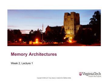
poor performance especially for applications that generate large amount of memorytraffic relative to the amount of computation they perform.Figure 5: GPGPU-Sim memory partition component [19, 20]The First-Ready First-Come-First-Served (FR-FCFS) scheduler gives higherpriority to requests that will access a currently open row in any of the DRAM banks.The scheduler will schedule all requests in the queue to open rows first. If no suchrequest exists it will open a new row for the oldest request.4.2 Stacked Memory OrganizationWe implement a 3D stacked memory which utilizes direct stacking of DRAM dieson a processing chip. We closely follow the stacked memory architecture provided bythe HMC consortium in our work. A concept of HMC memory organization is shownin the figure 6. The HMC memory is organized into vaults where each vault isfunctionally and operationally independent from the other. This allows parallel accesssimilar to DIMM structure for DRAM. Each vault consists of its own memorycontroller which is known as vault controller in HMC’s vernacular.11
Figure 6: HMC memory and in-memory processing logic organization [5]The vault controller is capable of handling refresh operations and manage allmemory operations with its vault. High speed serial links are used for communicationbetween the HMC and the host GPU. The packets coming from the host via links to theHMC for read/write requests are routed to their respective vault controllers using theinterconnect network. The write acknowledgements and read data follow the same pathback to the GPU.The DRAM dies in the stacked memory organization are connected by a denseinterconnect of Through-Silicon Vias (TSVs). These are metal connections that extendvertically through the entire stack. These interconnect path between the stacks are veryshort with lower capacitance than long PCB trace buses. Hence the data can be sent ata very high data rate on TSVs without having expensive and power hungry I/O divers.12
Furthermore, to increase parallelism in HMC stacked architecture, the dies aresegmented into vertical vaults. These vaults contain several partitions and each of thesepartitions contain several banks similar to a DRAM organization.According to HMC specifications [5], a single HMC can provide up to 320 GB/sof external memory bandwidth using eight high speed off-chip serial links (SerDeslinks). On the other hand, HMC is also capable of providing an aggregate internalbandwidth of 640 GB/s per cube, which consists of 16 vaults per cube. Each vault inthe HMC is analogous to a DRAM partition unit.Table 1: HMC configurationConfigurationNumber of links per package2, 4 (SerDes Links)Link lane speeds (Gb/s)12.5, 15, 25, 28, 30Memory density2GB, 4GB (under development)Number of vaults16, 32Memory banks2GB: 128 banks4GB: 256 banksMaximum aggregate link bandwidth480 GB/sMaximum DRAM data bandwidth320 GB/sMaximum vault data bandwidth10GB/s13
4.2.1 Integrate stacked memory with GPGPUFigure 7: GPGPU Sim memory architecture overview [19]We integrate stacked memory with GPGPU by replacing GDDR memory used byGPGPU with HMC’s memory architecture. Figure 7, shows the overview of memoryarchitecture used in current GPGPU.In GPGPU-sim memory organization each memory controller is connected to asingle DRAM die. This connection can be thought of as organized vertically toimplement one vault in HMC. Each of these vaults are functionally and operationallyindependent and each vault controller determines its own timing requirements. Refreshoperations are controlled by the vault controller i.e. memory controller in GPGPU-sim.14
Figure 8: HMC memory architecture implemented in GPGPU-simVault controller buffers are implemented by FIFO queues available in the memorypartition unit. The vault controller also has the ability to schedule references within aqueue completely out-of-order rather than by the order of their arrival.The access between the DRAM dies is facilitated by the TSV interconnects.Latency of this access is taken as 1.5 nsec or 1 cycle for a 667 MHz bus frequency [16].This latency is considering the worst case situation, when the data is to be accessedfrom the vault controller to the topmost DRAM layer in a stack of 8 DRAM dies. Theaccess latency caused by the TSVs is however very small as compared to the latencyof 100 cycles to access data from off-chip main memory. In GPGPU-sim, DRAMlatency queues is used to implement this access latency overhead of TSV (requests inthe DRAM latency queue wait for a fixed number of SIMT core cycles before they arepassed to the DRAM channel). The high bandwidth data transmission provided by theTSV channels is implemented in GPGPU-sim by changing the DRAM operating15
frequency in GTX 480 configuration. Figure 8 illustrates the conceptual view of thestacked memory architecture implemented on GPGPU-Sim.The HMC architecture contains quite a large design space to be explored in orderto optimize the performance. Within the DRAM memory stack we deal with specificdesign factors to expose a proper level of memory parallelism (implemented by vaultsin HMC) to effectively utilize the available TSV and off-chip link bandwidth. In theDRAM stack we have 2 fixed resource configuration (number of DRAM dies stackedand number of banks on each die): 128 and 256 bank configuration. Both of theseconfigurations consist of 16 vaults and four or eight DRAM dies. TSV bandwidthsavailable are 20, 40, 80, 160 and 320 GB/s [9]. The maximum bandwidth exploitableby the core is 640 GB/s [21].4.2.2 Off-chip linksCommunication between the stacked memory and the GPGPU is provided by theoff chip links. HMC architecture provides different choices of off-chip link bandwidthavailable from the stack memory to the host GPGPU. These links consist of multipleserial lanes with full duplex operation used for communication between the GPGPUprocessor cores and the stacked memory. The links transmit commands and data, inboth direction, enclosed in packets called “FLITs” which consist of a fixed number ofbits (according to the HMC-2.0 specifications, a flit size is 128 bits). Raw linkbandwidth configurations available are 80, 160, 240, and 320 GB /s [9].16
4.3 Processing In-MemoryProcessor architecture for host GPGPU and in-memory cores in our systemorganization are in-order processing units which use Single Instruction, MultipleThread (SIMT) model. In GPGPU-sim terminology, each processing unit is known asa shader core which is similar in scope with streaming multiprocessor (SM) in NVIDIAterminology [19]. We believe choosing SM as in-memory processor has severalbenefits, firstly, by using existing GPU design we ease the task of redevelopingdedicated processing units for PIM and promote reusability of off-the-shelf technology.Secondly, programmability of existing SMs in GPUs will provide a broad range ofapplications to completely utilize PIM [1]. Most importantly, using SM will provide auniform processing architecture [1].The shader cores used in both GPGPU and PIM has a SIMD width of 8 and uses a24-stage, in-order pipeline without forwarding [19]. The pipeline consists of six logicalpipeline stages which are fetch, decode, execute, memory1, memory2, and writeback.Post-dominator re-convergence mechanism is used to handle branch divergence inthreads. Figure 9 and 10 shows a detailed implementation of a single shader core inGPGPU [19] and the in-memory core that we used for PIM. The cores in PIMimplement the same thread scheduler and SIMD pipeline, however, the PIM cores donot have access to L1 cache units, L2 cache and shared memory. This is done to analyzePIM cores strictly with stacked memory and without the benefits from caching.17
Figure 9: Detailed GPU shader coreFigure 10: Detailed PIM logic core18
Furthermore, having L1 cache with PIM cores would complicate management ofcache coherency across GPGPU and PIM caches [6]. Deploying traditional cachecoherency protocols on our system with so many core would potentially requireadditional states and would also consume significant part of off-chip link bandwidth.19
5. Block Offloading MechanismIn this chapter we describe our new runtime mechanism that records and analyzesaverage execution time of all the thread blocks running on each GPGPU cores. It thendynamically determines possible thread block candidates for offload and then decidesat runtime whether the selected block candidate should really be offloaded to PIMcores.5.1 Identifying block offload candidateThe main objective when identifying candidates for offload is to find which threadblocks need higher memory bandwidth and offload these blocks to improveperformance and resource utilization in both GPGPU and PIM. Primarily, a block ofthreads could be considered for offload to PIM if its execution is taking much longertime to finish as compared to other thread blocks running on the same core. Thiscomparison is made between the blocks which were initialized/launched at the sametime and on the same GPGPU core. Number of times the other thread blocks havecompleted execution further strengthen the identification of slower thread blocks whichcan be offloaded.Increased execution time of a thread block could be due to multiple factors such ashigh thread divergence in the block or some of the threads in the block are waiting at abarrier or high cache miss rate causing frequent accesses to the main memory. The thirdcase is the one we are most interested in. L1 data cache miss rate and miss status holdingregister (MSHR) are the main indicator of this case. So, if the execution time of a blockcandidate on a GPGPU core is found to be higher than other blocks (running on the20
same core) and L1 cache miss rate of that core is higher than a threshold miss ratevalue, then this block becomes a possible candidate for offload to the PIM cores.Chapter 5.4.1 further explains the implementation in detail and describes the steps toidentify a slower block and determine whether that block is actually offloadeddepending on network traffic, availability of PIM cores to service the offloaded blockand number of active warps in the block.5.2 Block offload limitationsFew limitations to offload candidate blocks are –1. If the candidate block has divergent threads, then they must first converge beforebeing offloaded. Trying to offload a divergent thread block adds large amount ofcomplexity for managing SIMT stacks which control the divergence and reconvergence information GPGPU system.2. If any warp in the candidate block is wa
INTGRATING PROCESSING IN-MEMORY (PIM) TECHNOLOGY INTO GENERAL PURPOSE GRAPHICS PROCESSING UNITS (GPGPU) FOR ENERGY EFFICIENT COMPUTING A Thesis Presented to the Faculty of the Department of Electrical Engineering University of Houston In Partial Fulfillment of the Requirements for the Degree Master of Science in Electrical Engineering by