Transcription
APPENDIXSolutions to selected exercises2.3 Exercises1. Draw a ]5P structure diagram of a student record, using only those elementsspecified in the following description: A student record consists of the name ofthe student, the student registration number, date of birth, course attended, yearof course.Figure A.1Solution to Exercise 1.2. Draw simple ]5P structure diagrams for the following elements of the studentrecord specified in Exercise 1:(a) each student name is represented as last name followed by first name;(b) student registration number is year of entry combined with a unique applicationnumber;(c) date of birth is held as year, month and day (to facilitate sorting into age order).Figure A.2Solution to Exercise 2(a).Figure A.4Solution to Exercise 2(c).Figure A.3Solution to Exercise 2(b).271
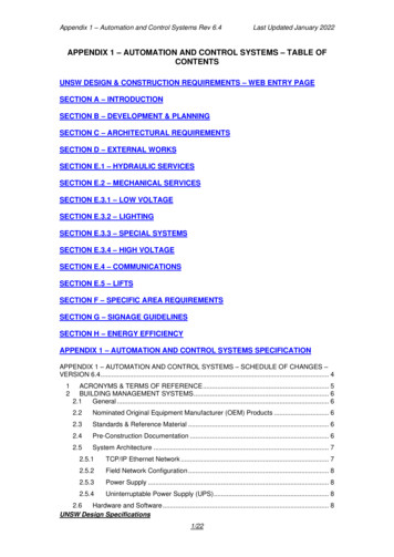
APPENDIX3. Draw the full JSP structure diagram for the student record described in Exercise1, incorporating the elements from Exercise 2.Figure A.5Solution to Exercise 3.4. Draw the JSP structure diagram for which the description is as follows. The academic year is a sequence of three terms: term 1, term 2 and term 3. Term 3 is asequence of revision followed by an examination.Figure A.6Solution to Exercise 4.5. Describe in words what the JSP structure diagram shown in Figure 2.10 (repeatedas Figure A. 7) represents.Figure A.7Structure diagram for Exercise 5 (repeat of Fig.2.1 0).A year is a sequence of the seasons Spring, Summer, Autumn and Winter. Springis a sequence of the months March, April and May; Summer is a sequence ofJune, July and August. The season of Autumn is a sequence of September, October and November and Winter is a sequence of December, January and February.The boxes Spring, Summer, Autumn and Winter are sequence components ofthe sequence structure year; each season is also a sequence structure withsequence components comprising the months of the season.272
SOLUTIONS TO SELECTED EXERCISES2.5 Exercises1. A company employee may be either a technical specialist or an administrator.Express this as a ]SP structure diagram.FigureA.aSolution to Exercise 1.2. A technical specialist within an organization may be a lawyer, an accountant, asystems analyst, an architect or a chemist. A company employee who is a chemistmay work in the field of organic or inorganic chemistry. Express this as a ]SPstructure diagram.Figure A.9Solution to Exercise 2.Figure A.lO also represents the situation described above. Note that as thestructure is a selection, the order of the selection components is not important.See Figure A.10 (p. 274).3. A company administrator could work in one of the following departments:personnel, payroll and pensions, registry and records, sales, marketing, orpurchasing. Use a ]SP structure diagram to describe this.See Figure A.ll (p. 274).4. Combine the details described in Exercises 1 to 3 to produce a single ]SP diagram.See Figure A. 12 (p. 274).273
Figure A.12 Solution to Exercise 4.Figure A.11 Solution to Exercise 3.Figure A.10 Alternative solution to Exercise 2.
SOLUTIONS TO SELECTED EXERCISES5. An athlete may be tall (5 feet 10 inches or above), or below this height; eachindividual will be male or female. Show how this can be expressed in a J5P structure diagram in different ways.The first possible solution (Fig. A.13) distinguishes between those who are talland those who are not, and then differentiates between male and female in eachcase.Figure A.13First possible solution to Exercise 5.The second possible solution (Figure A.14) differentiates between male andfemale athletes, and then distinguishes between those who are tall and those whoare not in each case.Figure A.14Second possible solution to Exercise 5.A third possible solution (Figure A.1S) differentiates between each classification of male, female, tall and not tall at the same level.Figure A.15Third possible solution to Exercise 5.If we were only interested in the tall female athletes, the simple diagram inFigure A.16 would be sufficient for our purposes.Figure A.16Solution to Exercise 5 for tall female athletes only.275
APPENDIX2.7 Exercises1. A century consists of 100 years. Each year lasts 365 days (ignoring leap years forthis exercise). A century could also be considered to consist of 10 decades. Showdifferent ways in which a century can be represented using JSP structure diagrams.A century is an iteration of decade (10 decades to a century) (Fig. A. 17).A century is an iteration of decade (10 decades to a century). A decade is aniteration of year (10 years to each decade) (Fig. A.1S).A century is an iteration of year (100 years to each century) (Fig. A.19).A century is an iteration of day (36500 days to each century) (Fig. A.20).A century is an iteration of decade (10 decades to a century). A decade is aniteration of year (10 years to each decade). A year is an iteration of day(365 days to each year) (Fig. A.21).Figure A.17 Centuryis an iteration of decade.Figure A.18 Century is aniterations of decade; decadeis an iteration of year.Figure A.19 Century isan iteration of year.Figure A.20 Centuryis an iteration of day.Figure A.21 Century is aniteration of decade; decadeis an iteration of year; year isan iteration of day.Figure A.22 Solutionto Exercise 2.2. A particular industry, e.g. travel, consists of a number of individual companies(such as travel agents). An individual company may have several branches in different locations. Each branch employs a number of staff. Illustrate the structureof the industry using a JSP diagram.A solution is given in Figure A.22 (above).276
SOLUTIONS TO SELECTED EXERCISES2.11 Exercises1. A vending machine dispenses a bar of chocolate when the correct money is inserted (there is only one type of chocolate bar available in the machine). Use astructure diagram to illustrate the activity of inserting money and taking a bar ofchocolate. Hint: sequence - the order of activities is important.Figure A.23Solution to Exercise 1.2. A more sophisticated vending machine dispenses a variety of bars of chocolate:plain chocolate, milk chocolate, fruit and nut, white chocolate (all at the sameprice). Draw a structure diagram to illustrate the action of choosing which bar ofchocolate is to be dispensed (ignoring all other activities, such as insertingmoney, for the present). Hint: selection - a bar of chocolate can only be one ofthose available, so the order is not important.Figure A.24Solution to Exercise 2.3. Consider the purchase of several chocolate bars from the machine described inExercise 2. Draw the structure diagram. Hints: selection - a bar of chocolate canonly be one of those available, so the order is unimportant; iteration - there maybe many purchases.Figure A.25Solution to Exercise 3.277
APPENDIX4. A book consists of a number of pages. On each page there are many lines, and oneach line there are many words. Draw the structure diagram. Hint: iteration - abook has many pages, etc.Figure A.26Exercise 4.Solution toFigure A.27Solution to Exercise 1.3.3 ExercisesDraw the input and output data file structures for the following:1. From a file of student records, you wish to list all students who are taking acourse in history.See Figure A.2? (above).2. From the same student file you wish to list all the female students who are takinga mathematics module.Three approaches are shown as a solution to this problem: (a) Figure A.2B; (b)Figure A.29; (c) Figure A.30.Figure A.28278One possible solution to Exercise 2.
SOLUTIONS TO SELECTED EXERCISESFigure A.29A second possible solution to Exercise 2.Figure A.30A third possible solution to Exercise 2.4. From the same student file you wish to list all the environmental science studentswho are female, and print the total number of these students and the grand totalof all students on the file.Figure A.31Solution to Exercise 4.5. From the same student file you wish to find the total number of all philosophystudents who are over 25 years old.Figure A.32Solution to Exercise 5.279
APPENDIX6. From an employee file you wish to list all the employees earning over 30,000who speak Italian.Figure A.33Solution to Exercise 6.7. From the same employee file you wish to print out details of all employees whoare not qualified in accountancy.Figure A.34Solution to Exercise 7.12. The data structure shown in Figure 3.5 (repeated as Figure A.35) represents a filethat may contain records A, B, C, D and E. These are the leaves of the tree. Is thefile structure compatible with each of the following record sequences:Figure A.3S(a) AB C D E(b) ACE(c) AD E(d) AB C E(e) ABE E(f) ABE280Data structure for Exercise 12 (repeat of Fig. 3.5).No, cannot have both Band CYesNo, must have B or C (but not both)No, cannot have both Band CYesYes
SOLUTIONS TO SELECTED EXERCISES(g)(h)(i)(j)(k)(I)B DEABCABD D D EA CD D EA CBEACCDENo, A is absentNo, must have E presentYesYesNo, cannot have both Band CYes4.7 ExercisesConsider the following problems, draw the input and output data file structures,identify the points of correspondence and merge to form the basic process structure in each case.1. From a file of student records, you wish to list all students who are taking acourse in history.The input and ouput structures, together with their points of correspondence areshown in Figure A.36. Input and output data structures merged on the points ofcorrespondence to form basic process structure are shown in Figure A.37.Figure A.36Points of correspondence for Exercise 1.Figure A.37The basic process structure for Exercise 1.2. From the same student file you wish to list all the female students who are takinga mathematics module.Taking the three approaches shown earlier (Exercises 3.3) as a solution to thisproblem: (a) Figure A.38; (b) Figure A.39; (c) Figure AAO.281
APPENDIXFigure A.38Points of correspondences for first possible solution to Exercise 2.Figure A.39Points of correspondence for second possible solution to Exercise 2.Figure A.40Points of correspondence for third possible solution to Exercise 2.5.4 ExercisesFrom the input and output file structures for the following exercises, identify the"housekeeping" activities that need to be performed and add process boxes tothe process structure diagram to allow these actions to be made.1. From a file of student records you wish to list all students who are taking a coursein history.282
SOLUTIONS TO SELECTED EXERCISESFigure A.41Solution to Exercise 1.6.6 ExercisesFrom the input and output file structures for the following exercises, introducedin the previous exercises, establish the points of correspondence, merge the datastructures to form a process structure, specify the conditions and operations andallocate these to the process structure.1. From a file of student records you wish to list all students who are taking a coursein history.The conditions are:c1c2c3not end of fileif history studentelseThe operations list is:1. Read student record from input file2.3.4.5.6.7.Open input file for inputOpen report file for outputWrite student record to outputreport fileStop processingClose input fileClose output file4.1Figure A.42The process structure for Exercise 1.283
APPENDIX7.5 Exercises1. Write the schematic logic for the structures shown in (a) Figure 7.13 (repeated asFigure A.43), (b) Figure 7.14 (repeated as Figure A.44), (c) Figure 7.15 (repeatedas Figure A.4S) and (d) Figure 7.16 (repeated as Figure A.46).The logic for (a) is:A seqB seqB operationsBendC itr while c1D seqD operationsDendo operationsCendA endFigure A.43 The process structure forExercise 1 (a).The logic for (b) is:A se1 if c1B seqB operationsB endA or if c2C seqE seqE operationsEendE operationsF operationsF seqF operations Figure A.44 The process structure forF endExercise 1 (b).CenciA or if c3 (else)D seqD operationsDendA endThe logic for (c) is:A se1 if c1B seqB operationsB endA or c2 (else)C itr while c3D seqD operationso operationsD endC endFigure A.45 The process structure forExercise 1 (c).A end284
SOLUTIONS TO SELECTED EXERCISESThe logic for (d) is:A seqB seqB operationsBendC sel if clE seqE operationsE endC or if c2 (else)E operationsF operationsF seqF operationsFendFigure A.46 The process structure forC endExercise 1 (d).D seqD operationsD endA end2. Reconstruct the process structures from the schematic logic:A seqB seqC seqdo C operationsC endD seqdo D operationsD endBendE sel if clF seqdo F operationsFendE or c2 (else)G seqdo G operationsG endE endH itr while c3J seqdo J operationsJ endH endA end(a)Figure A.47 The process structure forExercise 2(a).285
APPENDIX(b)AAitr while c1B sel if c2C itr while c5D seqdo D operationsD endC endB or if c3L seqE seqdo E operationsE endF sel c6p seqG seqdo G operationsG endH seqdo H operationsH endp endF or c7 (else)J seqdo J operationsJ endF endL endB or c4 (else)K seqdo K operationsK endB endendG opsFigure A.48286HopsThe process structure for Exercise 2(b}.
SOLUTIONS TO SELECTED EXERCISESConsider the following problems. Generate the schematic logic for each processstructure.1.From a file of student records, you wish to list all students who are taking acourse in history.The schematic logic is as follows:process data fi.le seqprocess start seq2. open input file for input3. open report file for output1. read student record from input fileprocess start endprocess body itr while not end of fileprocess student sel if history student'.write student record to output report file1. read student record from input fileprocess student or (else)1. read student record from input fileprocess student endprocess body endprocess finish seq6.close input file7. close output fileS.stop processingprocess finish endprocess data file end8.5 Exercises1. Convert the following schematic logic into the programming language of yourchoice.(a) In the following translation of the schematic logic into Pascal the schematic logicis given as comments, e.g. (* process total staff seq *):begin(* process total staff seq *)(* process start seq *)assign(staffile, 'staffile');reset(staffile); (* open staff file for input *)assign (report, 'report');rewrite(report); (* open report file for output *)staff tot : 0;(* set staff total to zero *)readln(staffile, name, job title);(* read staff record frominput staff file *)(* process start end *)287
APPENDIX(* process staff body itr while not end of staff file *)while not eof(staffile) dobegin(* process record seq *)staff tot : staff tot 1;(* add 1 to staff total *)readln(staffile, name, job title);(* read staff record frominput staff file *)(* process record end *)end;(* process staff body end *)(* process total seq *)writeln(report, 'Starlight Staff');(* write company title to output report file *)writeln(report, 'staff total: " staff tot: 8)(* write staff total to output report file *)writeln(report, 'October 1996');(* write date to output report file *)process total end(* process finish seq *)close(staffile);(* close staff file *)close(report);(* close report file *)(* stop processing *)end.(* process finish end *)(*process total staff end*)Consider the following problems. Produce the code for each process structure, usingthe programming language of your choice.3. From a file of student records, you wish to list all students who are taking acourse in history.In the following translation of the schematic logic into Pascal the schematic logicis given as comments, e.g. (* process data file seq *):begin(* process data file seq *)(* process start seq *)assign(stufile, 'stufile');reset(stufile);assign(report, 'report');rewrite(report);readln(stufile, name, course);(* process start end *)(* process body itr while not end of file *)while not eof(stufile) do(* process student sel if history student *)if course 'history' then288
SOLUTIONS TO SELECTED EXERCISES(*begin(write1n(report, name:20, course:10);readln(stufile, name, course);(* process student or (else) *)endelseread1n(stufi1e, name, course);(* process student end *)(* process body end *)(* process finish seq *)c1ose(stufi1e);c1ose(report);end.(* process finish end *)process data file end *)Note that it will be necessary to add the appropriate data declarations, etc., inorder to achieve a program that runs.9.5 ExercisesThe following structures represent files; valid record types are A, B, C, D and E.Records in error are of type x, and may be inserted at any point and in anynumber. The original records retain their order. Elaborate the structures belowfor errors of(a) insertion(b) substitution(c) omissionand then elaborate for further errors in each case.1. A simple input file, contains only two records, A followed by B (Fig. 9.13;repeated as Fig. A.49).Figure A.49The input file for Exercise 1 (repeat of Fig. 9.13).Figures A.50, A.51 and A.52 show the structure elaborated for errors of (a) insertion; (b) substitution and (c) omission respectively.289
APPENDIXFigure A.50Elaboration for errors of insertion: exercise 1.Figure A.51Elaboration for errors of substitution: exercise 1.Figure A.52Elaboration for errors of omission: exercise 1.2. An input file contains an initial record A, followed by several B records (Fig.9.14, repeated as Fig. A.S3).Figures A.S 4, A.S 5 and A.S 6 show the structure elaborated for errors of (a) insertion; (b) substitution and (c) omission respectively.Figure A.53 The input file forExercise 2 (repeat of Fig. 9.14).290Figure A.54 Elaboration for errors ofinsertion: exercise 2.
SOLUTIONS TO SELECTED EXERCISESFigure A.55Elaboration for errors of susbstitution: exercise 2.Figure A.56Elaboration for errors of omission: exercise 2.3. An input file contains an initial A record, followed by several B records, and thena single terminating record that may be of type C, D or E (Fig. 9.15, repeated asFig. A.57).Figures A.58, A.59 and A.60 show the structure elaborated for errors of (a) insertion; (b) substitution and (c) omission respectively.Figure A.57The input file for Exercise 3 (repeat of Fig. 9.15).291
APPENDIXFigure A.58Elaboration for errors of insertion: exercise 3.10.7 Exercises1. How could the process structure diagram for the case study be developed toallow for additional functions? Such functions could be, for example, to inspecta customer record without changing it, or to print a customer record.The process structure diagram is designed in order to allow such flexibility ofapproach. It would be possible to add another function as another selection part withinthe function iterated component. It would also be possible to remove a function, forexample, to prevent records from being deleted from the customer database. Theprocess structure diagram would have the appearance of Figure A.61 if inspectand print options were to be added. (The cancel option has been omitted forclarity).Note that the new functions inspect and print have been added including the abilityto deal with errors of insertion.2. Do you consider that elaborating for errors of insertion would be the best choiceif the customer database system were to run in batch rather than interactivemode? Explain your reasoning.Elaborating for errors of insertion is a suitable choice for dealing with dataentered interactively by a user; if the user makes an error, it is likely that furtherattempt(s) will be made until a correct entry is made (or the user terminates thesession).In the context of a batch system, it will not be possible for the user to respondto errors in the same way as with an interactive system; it is therefore necessary toconsider which type of error is most likely to be made if the updating of thecustomer database is performed by reference to an input file. If errors arise in therecords stored for processing against the main database, this could be regarded asan error of substitution because each erroneous record can be regarded as occurring in substitution for a correct record. It would be difficult to determine if errorsof omission had occurred, as, if there is no update record for a particular recordon the database, this may simply mean that the record concerned does not need tobe updated on this occasion.292
Figure A.60 Elaboration for errors of omission: exercise 3.Figure A.59 Elaboration for errors of substitution: exercise 3.
Figure A.61 Customer database system with inspect and print functions added.-A2, -A4, -A6,-AS, -AS, -A110
SOLUTIONS TO SELECTED EXERCISES11.5 Exercises1. Describe the role of posi t, admit and qui t in backtracking.Posi t and admi t are used to replace i f . . . then . . . else . . . whenthe information needed to test the condition on a selection is not available, and therefore it is not possible to decide with absolute certainty which selection branch shouldbe taken. Posit replaces the if . . . then . . . part ofthe selection; the resultof this is that one branch of the selection is entered without first testing the condition.It is possible, using this approach, that the wrong branch is taken. When sufficientinformation is available to establish whether or not the right path has been chosen, atest can be carried out; if the chosen path is the correct one, processing can continue as if the test had been performed at the usual point at the start of the selection. However, if it is found that the wrong branch has been selected, controlmust be transferred to the other branch, labelled by admit (replacing the elsebranch). The transfer of control to the admit part is executed by means of aqui t, which is normally implemented as a go to statement. It is important thatany intolerable side effects are avoided or reversed if control needs to be transferred from the posit branch to the admit branch.12.4 Exercises1. Explain the meaning of the following terms, and how they are relatedcorrespondencelack of correspondencestructure clash.A correspondence is said to occur between an input and an output data structure,where input is processed to generate output, if the elements in each are related by thefollowing rules: the elements are found in the same order the elements appear the same number of times the elements occur in the same contextIf these rules are satisfied at all appropriate points in the two data structures,the structures can be merged to form the basic process structure. If there is apoint in the data structures where the rules are broken, e.g. because the elementsdo not occur in the same order, there is a structure clash; this will prevent thedata structures from being merged to form a process structure. If there are boxesin one data structure that do not occur in the other, e.g. a title on an output report, this is a lack of correspondence which does not prevent the structures frombeing merged. All boxes in either data structure diagram must be represented bya box in the process structure diagram.A lack of correspondence means that an element on either the input file or theoutput file does not occur in the other file. Examples include: a total will be calculated during processing, a heading will be at the top of a page, and a pagenumber will be at the bottom of a report page; these will therefore appear on theoutput file but not on the input file.295
APPENDIXA structure clash indicates that there is conflict between some part of the input data structure and the output data structure because one or more of the rulesfor establishing a correspondence has been broken. This means that the inputand output data structures cannot be merged and another solution method mustbe adopted. It may be possible to redesign the data structures in order to avoidthe structure clash, or it may be necessary to redesign as if using an intermediatedata file by creating two process structures; this latter approach can be convertedto program inversion (the intermediate file is not physically created; the two programs communicate record-by-record).2. What are the three types of structure clash? Give an example of each.An ordering clash occurs when the records do not appear in the same order in theinput file and the output file; sorting the input file into the required order willresolve the clash.A boundary clash occurs when the boundaries (e.g. departments) on the inputfile do not match up with the boundaries (e.g. pages) on the output file. In thiscase, two programs need to be designed; an intermediate file is used as the outputfile from the first process and as the input file to the second process. Implementing program inversion does away with the need to create the intermediate file the two programs communicate by passing each record between the main program and the subprogram as and when required.An interleaving clash can be regarded as a combination of a boundary clashand an ordering clash; the records in the input file relating to a specific entity areinterspersed with other records, i.e. they are interleaved. One solution would beto sort the input file (as with an ordering clash). Another option would be todesign several different programs (one for each distinct entity) and implementthese using multiple program inversion.3. What is the difference between using an intermediate file and implementing program inversion when dealing with the problem of a structure clash?There is no difference in the structure of the two programs if an intermediate file iscreated or if program inversion is implemented. The difference that does occur is thatthe intermediate data file is not physically created if program inversion is implemented, as each record that would have been written to the intermediate datafile as output is instead passed to the other program for processing; this removesthe need for the second program to read the intermediate data file explicitlybecause the records are passed across as and when they require processing.4. Why is it necessary to delete references to an intermediate file in the subprogramwhen program inversion is being used?References to the intermediate file are no longer required as the main program willcall the subprogram passing the record that would have been read from the intermediate file. The records are passed between the main program and thesubprogram in the same order as they would have been written to the intermediate file (and read from the intermediate file). Therefore there is no need for theintermediate file to be created in a physical sense, it is only used as an aid to thedesign of the two communicating programs.296
SOLUTIONS TO SELECTED EXERCISES13.6 Exercises1. Show how you would dismember the process structure diagram shown in Figure13.9 (repeated as Fig. A.62) (a) graphically; and (b) in tabular form.06asModule 4Figure A.62Module 5The process structure diagram for Exercise 13.6.1 (repeat of Fig. 13.9).Note that module 3 is completely contained within module 2; it would be possible to merge these into a single module if required.The resume execution table is shown as Table A.1, the module link table asTable A.2 and the module link table produced by merging modules 2 and 3 asTable A.3.Table A.2Table A.1 Resume executiontable: exercise SC,D,G,J,KC, D, G, J, KC,D,G,J,KE, FD,G,J,KH, IH, ID, G, J, KasasModule link table: exercise 1.ModulenameElementarycomponentsMod 1A,SMod 2C, D, G, J, KMod 3D,G,J, KMod 4Mod 5E, FH, ModModModModModNILModModNILModModMod2224545353297
APPENDIXTable A.3Module link table: exercise 1. merged modules.ModulenameElementarycomponentsMod 1A.BMod 2C. D. G. F. J. KMod 3Mod 4E. odModModModNILModModMod22234242Table A.3 shows that the two modules, where module 3 was contained withinmodule 2, can be merged into a single module. The overhead for doing this isthat there will be some cases where the elementary component C will be loadedwhen it is not required, i.e. module 2 will be loaded where the "old" module 3would have been loaded.If a large amount of code is involved with elementary component C it might beconsidered wasteful to load the entire module if it is known that c will not berequired; in these circumstances, the previous dismemberment would be employed.2. Show how you would dismember the process structure diagram shown in Figure13.10 (repeated as Fig. A.63) (a) graphically; and (b) in tabular form.The resume execution table is shown as Table AA and the module link table asTableA.5.Module 1Module 2Q6Module 3Figure A.63Q9Module 4.Module 5,The process structure diagram for Exercise 2 (repeat of Fig. 13.10)with graphic dismemberment.298
SOLUTIONS TO SELECTED EXERCISESTable A.4Resumeexecution table: exercise 2.Resumepoints010203040506070809010Table A.SModule link table: exercise tsAMod 1Mod 2AB, CJ, KJ, KMod 3D, G, J, KJ, KMod 4E, FMod 5H, IB, CD, G,D, G,E, FE, FD, G,H, IH, ID, G,J, odModModModNILModModModMod2334543533. Show how you would dismember the process structure diagram shown in Figure13.11 (repeated as Fig. A.64) (a) graphically; and (b) in tabular form.The resume execution table is shown as Table A.6 and the module link table as TableA.7.r----------J E l:!.I ]JModule 20507Figure A.64 The process structure diagram for Exercise 3 (repeat of Fig. 13.11)with graphic dismemberment.Table A.SResumeexecution table: exercise 3.Resumepoints0102030405060708Table A.7Module linke table: exercise sA, B, CA,B, CMod 1A, B,CMod 2D, F, HMod 3Mod 4ED, F, HD, F, HED, F, HGD, F, dModModNILModMod1223422299
APPENDIX4. Show how you would dismember the process structure diagram shown in Figure13.12 (repeated as Fig. A.65) (a) graphically; and (b) in tabular form.The resume execution table is shown as Table A.S and the module link table as TableA.9.Module 1j"" J----------- o 2IIJ0607Module 3Figure A.65 The process structure diagram for Exercise 4 (repeat of Fig. 13.12)with graphic dis
APPENDIX 3. Draw the full JSP structure diagram for the student record described in Exercise 1, incorporating the elements from Exercise 2. Figure A.5 Solution to Exercise 3. 4. Draw the JSP structure diagram for which the description is as follows.The aca demic year is a sequence of three terms: term 1, term 2 and term 3.