Transcription
OWNER'SMANUALWARNINGFAILURE TO FOLLOW THESEWARNINGS MAY RESULT INSERIOUS INJURY AND/ORPROPERTY DAMAGE.Owner must ensure that allplayers know and follow theserules for safe operation of theunit.!!!!!!!!!!Do not dunk on this unitDo not hang from any part of the unit,including the backboard, rim, or net.Do not slide, climb, or play on pole.Keep organic material away frompole base. Grass, litter, etc. couldcause corrosion and /or deterioration.Check pole system twice a year forsigns of corrosion (rust, pitting,chipping). Remove rust and/or loosepaint completely and repaint withexterior enamel paint. If rust haspenetrated through the steelanywhere, replace pole immediately.Check unit before each use for loosehardware, excessive wear, and signsof corrosion and repair before using.During play, use extreme caution tokeep players face away from thebackboard, rim, and net.Wear a mouthguard when playing toavoid dental injuries.When adjusting height, keep handsand fingers away from moving parts.During play, do not wear jewelry(rings, watches, necklaces, etc.).Objects may entangle in net.Model PROBASKETBALL SYSTEMMODEL NUMBERB2309Thank you for purchasing our basketball system. We try hard to ensure that our products are of high qualityand free of manufacturing defects and of missing parts. However, if you have any problems with yourbasketball pole, such as a manufacturing defect or a missing part, please DO NOT RETURN IT TO THESTORE. Call us at:TOLL FREE 1-888-USA-GOAL(THIS IS A CONSUMER ONLY NUMBER)FAX: (812) 467-1399Or write us at:CUSTOMER SERVICE DEPT., P.O. Box 889, Evansville, IN 47706Please provide model number, serial number, and/or part number of the product and/or part when you call orwrite. These numbers can be found on the product, packaging, or in this owner's manual.To make assembly of your basketball pole easier, use the Hardware Identifier on page 2 and 3 to identify and sort all fasteners.Do not tighten hardware until instructed to do so. If hardware is tightened too soon, mounting holes may not align and partsmay not fit together. Leave locknuts slightly loose until you are instructed to tighten them.Read this manual all the way through before starting to put up your pole. Then read each step completely before beginning that step. Somemay be shipped inside larger tubes. Check inside tubes before assembling or ordering parts.1smaller parts2L-6627-00
2
3
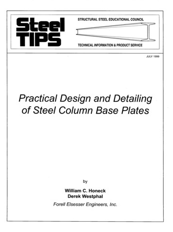
WELCOME TO THE FAMILY OF GOALRILLATM OWNERSIn order to have the safest fun and longest use of your GoalrillaTM system, please note and heed the following:1.Prior to main post preparation and goal assembly, call utility services for location of underground utility linesbefore you dig.2.Vertical main post assembly is a two part process.Day 1.Day 2.Day 3.Day 4.3.PART 1Complete Anchor System InstallationInstructions. (Below)Allow concrete to cure.Allow concrete to cure.Allow concrete to cure.Day 5.PART 2Complete GoalrillaTM assembly instructions.For safety measures have at least 3 capable persons to assist you in assembly of your GoalrillaTM Goal.ANCHOR SYSTEM INSTALLATION INSTRUCTIONS (Day 1)Items needed (not included)8 - 80 lb. bags of concrete1 - post hole digger1 - concrete form (see note after step 2)1 - 5/16" wrench1 - wheel barrow1 - garden hose1 - levelFigure 1Before digging the hole for this pole, checkfor buried power, gas, water, andtelecommunication lines! Failure to do socould result in serious or fatal injury! Contactyour local utility company if unsure.1.2.Determine the location of the goal. Position the holeclose to the playing surface without making contact.Dig a hole 16" in diameter and 48" below the playingsurface. (See Figure 1)Assemble anchor system as follows: Thread nut (#35)to bottom of threads on anchor bolt (#39) insertthreads of anchor bolt (#39) through hole on anchorplate (#38) and secure with nut (#35). Repeat this stepfor the remaining anchor bolts. See Figure 2. Note:Each leg of anchor bolts should face the anchor boltto the right. See Detail A.Figure 24Note: It is recommended that you use some sort ofconcrete form for the top 4" of the concrete.Cardboard forms can be purchased at some hardwareand home stores or a wooden form can beconstructed out of 2 x 4's.3.Mix and pour concrete into hole. Follow instructionson concrete bag. Stop about 18" below court level.4.Insert four reinforcement bars (#40) into concrete8" apart creating a square in center on hole.5.Finish pouring concrete up to court level.6.Push anchor system into concrete and agitate to workout voids in concrete. Immediately use a level to leveland square anchor plate to playing surface. Cleanoff any concrete that may be on exposed threads.Note: The bottom four nuts will be foreverembedded in concrete.Let concrete stand for a MINIMUM of 72 hours.
GOALRILLATM I ASSEMBLY INSTRUCTIONS (Day 5)NOTE: It is important for the installer to understandthe necessity of the nylon washers (#5) provided.These washers adequately space painted parts at allpivot points. Neglecting the use of these washers willresult in rusted parts.Figure 3NOTE: All board arms are made of rectangular tubing.Tightening hardware too tight may damage tubingand make adjustment of system difficult.1.Slide Actuator Sleeve (#15) over Actuator (#16) andplace Actuator Cap (#13) on top. Slide Pivot Tube(#14) in hole near the top of Actuator until equalamounts stick out on both sides of Actuator. SeeFigure 3. NOTE: It may be necessary to use ahammer or rubber mallet to tap in Spacer.2.Lay Pole (#2) on its side on two padded saw horses.Attach Actuator (#16) to Pole (#2) using one bolt(#19), split lockwasher (#18), washer (#3) and twoplastic washers (#5) to thread into each side ofActuator. See Figure 3. Do not tighten bolts yet.3.Insert Pole Cap (#1) into top of Pole (#2). It may benecessary to use a hammer or rubber mallet to tapCap in.Figure 44.Attach lower arm (#11) to Pole (#2), as shown inFigure 4, using a bolt (#8), two flatwashers (#3), fourplastic washers (#5) and hex nut (#4). Note: makesure "Goalrilla lettering is right side up. Do NOTtighten bolt (#8) at this time.5.Secure Actuator (#16) to Lower Arm (#11) using onebolt (#8), two flatwashers (#3), four plastic washers(#5) and one hex nut (#4). See Figure 5. Tighten bothbolts (#8) securing Lower Arm (#11). Important!Tighten bolts snug but, do not over tighten. BoardArms must pivot freely.6.Figure 5If the four Tube Plugs (#10) are not already installedinsert them into open ends of Lower Arm (#11). Itmay be necessary to use a hammer or rubber malletto tap plug in.5
7.Attach Upper Arm (#6) to Pole (#2), as shown in Figure6, using a bolt (#7), two flatwashers (#3), four plasticwashers (#5) and hex nut (#4). Tighten bolts snugbut, do not over tighten. Board Arms must pivotfreely.8.If the four Tube Plugs (#10) are not already installedinsert them into open ends of Upper Arm (#6). It maybe necessary to use a hammer or rubber mallet totap plug in.Figure 6PLACING THE POST ON THE ANCHOR SYSTEMREQUIRES AT LEAST FOUR CAPABLE ADULTS.POLE WILL WANT TO LEAN WHILE ATTEMPTING TOSTAND IT UP ON ANCHOR BOLTS.9.Figure 7Locate hardware needed to mount pole to anchorbolts. You will need, eight flatwashers (#37), fourlock washers (#36), four hex nuts (#35) and fourthread protectors (#34).10. Put a flat washer (#37) on each anchor bolt. Lift postonto anchor system and secure with one flatwasher(#37), one lock washer (#36) and one hex nut (#35)for each anchor bolt. Tighten all four hex nuts tight.BE SURE CONCRETEHAS BEEN ALLOWEDTO CURE FOR ATLEAST 3 DAYS11. Slide Actuator Crank (#42) onto shaft on the bottomof Actuator (#16). Line up hole in shaft with hole inActuator Crank and insert Pull Pin (#41) to secure.12. To aid in the assembly of the backboard lower thebackboard, by turning the Actuator Crank, until thelower arm makes contact with the Safety Stop.Figure 86
ATTACHING BACKBOARD TO BOARD ARMSREQUIRES AT LEAST FOUR CAPABLE ADULTS.13. With at least three capable people, raise thebackboard assembly up and have the fourth attachLower Board Arms to lower mounting tubes onbackboard using two bolts (#21), four Board Bushings(#22) (shipped already installed), two plastic washers(#5), two washers (#3) and two hex nuts (#4). SeeFigure 9. Do NOT over tighten these bolts. This isa pivot point. Snug is tight enough.14. Attach Upper Board Arms to upper mounting tubeson backboard using two bolts (#20), four BoardBushings (#22) (shipped already installed), two plasticwashers (#5), two washers (#3) and two hex nuts(#4). See Figure 9. Do NOT over tighten these bolts.This is a pivot point. Snug is tight enough.Figure 10Figure 915. Remove protective backboard covering and mount GoalAssembly (#28) and Rim Pad (#27) to Backboard, asshown in Figure 10, using four bolts (#29), eight washers(#26), four lockwashers (#25) and four nuts (#24).Tighten fasteners finger tight, leave them loose enoughto level rim.16. Place a level across rim assembly and adjust rim until itis level. Finish tightening the four nuts.17. Attach Rim Cover Plate (#31) using four screws (#32).See Figure 10. CAUTION! Never use rim withcoverplate removed!18. Check all nuts and bolts everything is tightenedproperly. Do NOT over tighten pivot points, snug is tightenough.19. Adjust unit to 7-1/2 feet. Use a tape measure to measurefrom the top of the rim to the playing surface. StickHeight Decal (#17) to back of actuator (#16) with the"7.5" mark aligned with bottom of Actuator Sleeve (#15).See Figure 11.Figure 1120. See your POD owners manual for instructions oninstalling and using your POD system.7
GOALRILLATM CARE INFORMATION- BACKBOARD Items needed to clean backboard:- 100% cotton soft cloth, (only)- Mild dish washing liquid for soap- Luke warm water- Mild plastic polish to minimize scratchesRinse backboard with lukewarm water. Wash gently with a 100% Cotton soft cloth, lukewarm water and mild soap. Do not scrub. Rinse backboard withlukewarm water again. Dry with 100% cotton soft cloth. To minimize scratches and minor abrasions to your backboard, apply a mild polish such as Johnson’sPaste Wax, Novus Plastic Polish #1 or Mirror Glaze Plastic Polish. Strong cleansers will damage backboard and void warranty.– RIM –HANGING ON THE RIM WILL VOID YOUR WARRANTY. Rims are not warranted for any defects other than workmanship. Torn back plates, damagedsprings, bent rings, damaged eye bolts, and torn or distorted rim supports result from hanging on the rim and are not warranted.The goal should not be cranked under 7' or over 10'. Adjustments of the goal should be done under adult supervision.When attempting slam dunk activity you should always wear a mouth guard to avoid dental injury.LIMITED LIFETIME WARRANTYSubject to proper installation and normal use, Escalade Sports warrants, subject to the limitations below, to the original retail purchaser all structuralcomponents of the Goalrilla System to be free of defects in material and workmanship for the duration of ownership by the original retail purchaser.Merchandise must be shipped prepaid with a copy of proof of purchase to our factory for examination to see whether it needs to be repaired orreplaced. Any labor costs, travel expenses and any other changes involved in the removal, installation or replacement of the defective/repaired partsfrom/to your Goalrilla System will be your (the purchaser's) responsibility. Shipping charges for replaced or warranted merchandise being sent back tothe customer from our factory must be prepaid by the customer in advance. If not, the replacement shipment will be sent out collect.Escalade Sports reserves the right to examine photographs or physical evidence of merchandise claimed to be defective, and to recover saidmerchandise, prior to authorization of warranty claims. A "Returned Goods Authorization" number may be required, please call for details prior to thereturn of any photographs or merchandise.This warranty is expressly in lieu of all warranties, expressed or implied, including warranties of merchantability or fitness for use. Escalade Sportsdoes not assume or authorize any person or representative to assume for us, any other liability in connection with the sale of our products.The remedy of repair or replacement stated above is our exclusive remedy. Escalade Sports will not be liable for any other damages or expenseswhich may incur, including but not limited to incidental or consequential damages. Escalade Sports assumes no other obligations or liability on thepart of the purchaser, and Escalade Sports neither assumes nor authorizes any other person to assume for it any other liability in connection with thegoods sold.What is Not Covered by This Warranty Any merchandise subjected to abuse, negligence, improper installation, vandalism, acts of God, alteration of product, or any other events beyondthe control of Escalade Sports.Paint or rusted parts. Paint kits will be available to assist in normal maintenance.HANGING ON RIM WILL VOID YOUR WARRANTY: Rims are not warranted for any defects other than workmanship. Torn back plates,damaged springs, bent rings, damaged eyebolts, and torn or distorted rim supports result from hanging on the rim and are not warranted.Shipping charges both ways. Note: Any merchandise shipped to Escalade Sports collect will be refused.Dealer service charges, labor charges and travel expenses associated with replacement of repair of warranty item.WARRANTY GUIDELINES1.2.Keep your proof of purchase (original retail purchaser). Without it, we will not be able to proceed with any warranty service.Call or write Escalade Sports Inc. to receive a Return Authorization # and allow us to better guide you with your specific needs.1-888-USA-GOAL / Warranty Dept.Or Write us at:Escalade Sports Inc. - P.O. Box 889, Evansville, IN 47706 - Attn: Warranty Dept.Or E-mail us at: customerservice@escaladesports.com8
829303132333435363738394041424344Part 4A-6550-001A-6303-012L-6634-00Description6 X 8 Tube PlugPost Assembly1/2 Flat Washer1/2-13 Nylon Locknut1-1/4" OD Plastic WasherUpper Board Arm1/2-13 X 11" Hex Bolt-Grade 51/2-13 X 12 Hex Bolt-Grade 51-1/2 X 2-1/2 Tube Plug2 X 4 Tube PlugLower Board ArmGoalrilla DecalActuator CapPivot TubeActuator SleeveActuatorHeight Decal1/2 Split Lock Washer1/2-13 X 1" Hex Bolt1/2-13 X 4 Hex Bolt1/2-13 X 4-1/2 Hex BoltBoard BushingBackboard Assembly3/8-16 Hex Nut3/8 Split Lockwasher3/8 STD Washer5X5 Rim PadGoal Assembly3/8-16 X 2" Hex BoltNetRim Cover Plate#10 x 1/2 Thread Forming Scr.Board Arm Stop Cover5/8 Thread Protector5/8-11 Hex Nut5/8 Split Lockwasher5/8 SAE FLAT WSHR ZNCAnchor Plate5/8-11 X 18 "J" Bolt#3 X 40" RebarPull PinActuator HandlePODThis 81441111
102L-6627-00
Day 1. Complete Anchor System Installation Instructions. (Below) Day 2. Allow concrete to cure. Day 3. Allow concrete to cure. Day 4. Allow concrete to cure. PART 2 Day 5. Complete Goalrilla. TM. assembly instructions. 3. For safety measures have at least 3 capable persons to assist you in assembly of your Goalrilla. TM . Goal. Figure 1 Figure 2