Transcription
PIC12F508/509/16F505Data Sheet8/14-Pin, 8-Bit Flash Microcontrollers 2009 Microchip Technology Inc.Downloaded from Arrow.com.DS41236E
Note the following details of the code protection feature on Microchip devices: Microchip products meet the specification contained in their particular Microchip Data Sheet. Microchip believes that its family of products is one of the most secure families of its kind on the market today, when used in theintended manner and under normal conditions. There are dishonest and possibly illegal methods used to breach the code protection feature. All of these methods, to ourknowledge, require using the Microchip products in a manner outside the operating specifications contained in Microchip’s DataSheets. Most likely, the person doing so is engaged in theft of intellectual property. Microchip is willing to work with the customer who is concerned about the integrity of their code. Neither Microchip nor any other semiconductor manufacturer can guarantee the security of their code. Code protection does notmean that we are guaranteeing the product as “unbreakable.”Code protection is constantly evolving. We at Microchip are committed to continuously improving the code protection features of ourproducts. Attempts to break Microchip’s code protection feature may be a violation of the Digital Millennium Copyright Act. If such actsallow unauthorized access to your software or other copyrighted work, you may have a right to sue for relief under that Act.Information contained in this publication regarding deviceapplications and the like is provided only for your convenienceand may be superseded by updates. It is your responsibility toensure that your application meets with your specifications.MICROCHIP MAKES NO REPRESENTATIONS ORWARRANTIES OF ANY KIND WHETHER EXPRESS ORIMPLIED, WRITTEN OR ORAL, STATUTORY OROTHERWISE, RELATED TO THE INFORMATION,INCLUDING BUT NOT LIMITED TO ITS CONDITION,QUALITY, PERFORMANCE, MERCHANTABILITY ORFITNESS FOR PURPOSE. Microchip disclaims all liabilityarising from this information and its use. Use of Microchipdevices in life support and/or safety applications is entirely atthe buyer’s risk, and the buyer agrees to defend, indemnify andhold harmless Microchip from any and all damages, claims,suits, or expenses resulting from such use. No licenses areconveyed, implicitly or otherwise, under any Microchipintellectual property rights.TrademarksThe Microchip name and logo, the Microchip logo, dsPIC,KEELOQ, KEELOQ logo, MPLAB, PIC, PICmicro, PICSTART,rfPIC and UNI/O are registered trademarks of MicrochipTechnology Incorporated in the U.S.A. and other countries.FilterLab, Hampshire, HI-TECH C, Linear Active Thermistor,MXDEV, MXLAB, SEEVAL and The Embedded ControlSolutions Company are registered trademarks of MicrochipTechnology Incorporated in the U.S.A.Analog-for-the-Digital Age, Application Maestro, CodeGuard,dsPICDEM, dsPICDEM.net, dsPICworks, dsSPEAK, ECAN,ECONOMONITOR, FanSense, HI-TIDE, In-Circuit SerialProgramming, ICSP, Mindi, MiWi, MPASM, MPLAB Certifiedlogo, MPLIB, MPLINK, mTouch, Octopus, Omniscient CodeGeneration, PICC, PICC-18, PICDEM, PICDEM.net, PICkit,PICtail, PIC32 logo, REAL ICE, rfLAB, Select Mode, TotalEndurance, TSHARC, UniWinDriver, WiperLock and ZENAare trademarks of Microchip Technology Incorporated in theU.S.A. and other countries.SQTP is a service mark of Microchip Technology Incorporatedin the U.S.A.All other trademarks mentioned herein are property of theirrespective companies. 2009, Microchip Technology Incorporated, Printed in theU.S.A., All Rights Reserved.Printed on recycled paper.Microchip received ISO/TS-16949:2002 certification for its worldwideheadquarters, design and wafer fabrication facilities in Chandler andTempe, Arizona; Gresham, Oregon and design centers in Californiaand India. The Company’s quality system processes and proceduresare for its PIC MCUs and dsPIC DSCs, KEELOQ code hoppingdevices, Serial EEPROMs, microperipherals, nonvolatile memory andanalog products. In addition, Microchip’s quality system for the designand manufacture of development systems is ISO 9001:2000 certified.DS41236E-page 2Downloaded from Arrow.com. 2009 Microchip Technology Inc.
PIC12F508/509/16F5058/14-Pin, 8-Bit Flash MicrocontrollersDevices Included In This Data Sheet: PIC12F508 PIC12F509 PIC16F505High-Performance RISC CPU: Only 33 Single-Word Instructions to Learn All Single-Cycle Instructions Except for ProgramBranches, which are Two-Cycle 12-Bit Wide Instructions 2-Level Deep Hardware Stack Direct, Indirect and Relative Addressing modesfor Data and Instructions 8-Bit Wide Data Path 8 Special Function Hardware Registers Operating Speed:- DC – 20 MHz clock input (PIC16F505 only)- DC – 200 ns instruction cycle (PIC16F505only)- DC – 4 MHz clock input- DC – 1000 ns instruction cycleSpecial Microcontroller Features: 4 MHz Precision Internal Oscillator:- Factory calibrated to 1% In-Circuit Serial Programming (ICSP ) In-Circuit Debugging (ICD) Support Power-On Reset (POR) Device Reset Timer (DRT) Watchdog Timer (WDT) with Dedicated On-ChipRC Oscillator for Reliable Operation Programmable Code Protection Multiplexed MCLR Input Pin Internal Weak Pull-Ups on I/O Pins Power-Saving Sleep mode Wake-Wp from Sleep on Pin Change Selectable Oscillator Options:- INTRC: 4 MHz precision Internal oscillator- EXTRC: External low-cost RC oscillator- XT:Standard crystal/resonator- HS:High-speed crystal/resonator(PIC16F505 only)- LP:Power-saving, low-frequency crystal- EC:High-speed external clock input(PIC16F505 only) 2009 Microchip Technology Inc.Downloaded from Arrow.com.Low-Power Features/CMOS Technology: Operating Current:- 175 μA @ 2V, 4 MHz, typical Standby Current:- 100 nA @ 2V, typical Low-Power, High-Speed Flash Technology:- 100,000 Flash endurance- 40 year retention Fully Static Design Wide Operating Voltage Range: 2.0V to 5.5V Wide Temperature Range:- Industrial: -40 C to 85 C- Extended: -40 C to 125 CPeripheral Features (PIC12F508/509): 6 I/O Pins:- 5 I/O pins with individual direction control- 1 input only pin- High current sink/source for direct LED drive- Wake-on-change- Weak pull-ups 8-Bit Real-Time Clock/Counter (TMR0) with 8-BitProgrammable PrescalerPeripheral Features (PIC16F505): 12 I/O Pins:- 11 I/O pins with individual direction control- 1 input only pin- High current sink/source for direct LED drive- Wake-on-change- Weak pull-ups 8-Bit Real-Time Clock/Counter (TMR0) with 8-BitProgrammable PrescalerDS41236E-page 3
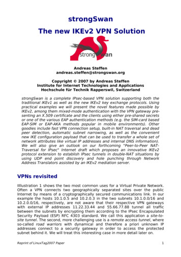
PIC12F508/509/16F505Pin DiagramsPDIP, SOIC, /OSC23GP3/MCLR/VPP4PIC12F508/509PDIP, SOIC, e 4Downloaded from S16151413PIC16F505 16-Pin Diagram RC2RC5/TOCKI6RB2RC31053RC4RB3/MCLR/VPP 2009 Microchip Technology Inc.
PIC12F508/509/16F505Program MemoryData MemoryDeviceI/OFlash (words)SRAM 1PIC16F505102472121 2009 Microchip Technology Inc.Downloaded from Arrow.com.DS41236E-page 5
PIC12F508/509/16F505Table of Contents1.0 General Description. 72.0 PIC12F508/509/16F505 Device Varieties . 93.0 Architectural Overview . 114.0 Memory Organization . 175.0 I/O Port . 316.0 Timer0 Module and TMR0 Register . 357.0 Special Features Of The CPU . 418.0 Instruction Set Summary . 579.0 Development Support. 6510.0 Electrical Characteristics . 6911.0 DC and AC Characteristics Graphs and Charts . 8112.0 Packaging Information. 91Index . 105The Microchip Web Site . 107Customer Change Notification Service . 107Customer Support . 107Reader Response . 108Product Identification System. 109TO OUR VALUED CUSTOMERSIt is our intention to provide our valued customers with the best documentation possible to ensure successful use of yourMicrochip products. To this end, we will continue to improve our publications to better suit your needs. Our publications will berefined and enhanced as new volumes and updates are introduced.If you have any questions or comments regarding this publication, please contact the Marketing Communications Department viaE-mail at docerrors@mail.microchip.com or fax the Reader Response Form in the back of this data sheet to (480) 792-4150.We welcome your feedback.Most Current Data SheetTo obtain the most up-to-date version of this data sheet, please register at our Worldwide Web site at:http://www.microchip.comYou can determine the version of a data sheet by examining its literature number found on the bottom outside corner of any page.The last character of the literature number is the version number, (e.g., DS30000A is version A of document DS30000).ErrataAn errata sheet, describing minor operational differences from the data sheet and recommended workarounds, may exist for currentdevices. As device/documentation issues become known to us, we will publish an errata sheet. The errata will specify the revisionof silicon and revision of document to which it applies.To determine if an errata sheet exists for a particular device, please check with one of the following: Microchip’s Worldwide Web site; http://www.microchip.com Your local Microchip sales office (see last page) The Microchip Corporate Literature Center; U.S. FAX: (480) 792-7277When contacting a sales office or the literature center, please specify which device, revision of silicon and data sheet (includeliterature number) you are using.Customer Notification SystemRegister on our web site at www.microchip.com/cn to receive the most current information on all of our products.DS41236E-page 6Downloaded from Arrow.com. 2009 Microchip Technology Inc.
PIC12F508/509/16F5051.0GENERAL DESCRIPTIONThe PIC12F508/509/16F505 devices from MicrochipTechnology are low-cost, high-performance, 8-bit,fully-static, Flash-based CMOS microcontrollers. Theyemploy a RISC architecture with only 33 single-word/single-cycle instructions. All instructions are singlecycle (200 μs) except for program branches, whichtake two cycles. The PIC12F508/509/16F505 devicesdeliver performance an order of magnitude higher thantheir competitors in the same price category. The 12-bitwide instructions are highly symmetrical, resulting in atypical 2:1 code compression over other 8-bitmicrocontrollers in its class. The easy to use and easyto remember instruction set reduces development timesignificantly.1.1ApplicationsThe PIC12F508/509/16F505 devices fit in applicationsranging from personal care appliances and securitysystems to low-power remote transmitters/receivers.The Flash technology makes customizing applicationprograms (transmitter codes, appliance settings,receiver frequencies, etc.) extremely fast and convenient. The small footprint packages, for through hole orsurface mounting, make these microcontrollers perfectfor applications with space limitations. Low cost, lowpower, high performance, ease-of-use and I/O flexibility make the PIC12F508/509/16F505 devices very versatile even in areas where no microcontroller use hasbeen considered before (e.g., timer functions, logic andPLDs in larger systems and coprocessor applications).The PIC12F508/509/16F505 products are equippedwith special features that reduce system cost andpower requirements. The Power-on Reset (POR) andDevice Reset Timer (DRT) eliminate the need for external Reset circuitry. There are four oscillator configurations to choose from (six on the PIC16F505), includingINTRC Internal Oscillator mode and the power-savingLP (Low-Power) Oscillator mode. Power-Saving Sleepmode, Watchdog Timer and code protection featuresimprove system cost, power and reliability.The PIC12F508/509/16F505 devices are available inthe cost-effective Flash programmable version, whichis suitable for production in any volume. The customercan take full advantage of Microchip’s price leadershipin Flash programmable microcontrollers, whilebenefiting from the Flash programmable flexibility.The PIC12F508/509/16F505 products are supportedby a full-featured macro assembler, a software simulator, an in-circuit emulator, a ‘C’ compiler, a low-costdevelopment programmer and a full featured programmer. All the tools are supported on IBM PC andcompatible machines.TABLE 1-1:PIC12F508/509/16F505 DEVICESPIC12F508PIC12F509PIC16F505ClockMaximum Frequency of Operation (MHz)4420MemoryFlash Program Memory (words)51210241024Data Memory (bytes)254172TMR0TMR0TMR0YesYesYesI/O Pins5511Input Pins111Internal Pull-upsYesYesYesIn-Circuit Serial ProgrammingYesYesYesNumber of Instructions3333338-pin PDIP, SOIC,MSOP, DFN8-pin PDIP, SOIC,MSOP, DFN14-pin PDIP, SOIC,TSSOPPeripheralsTimer Module(s)Wake-up from Sleep on Pin ChangeFeaturesPackagesThe PIC12F508/509/16F505 devices have Power-on Reset, selectable Watchdog Timer, selectable code-protect, high I/O currentcapability and precision internal oscillator.The PIC12F508/509/16F505 devices use serial programming with data pin RB0/GP0 and clock pin RB1/GP1. 2009 Microchip Technology Inc.Downloaded from Arrow.com.DS41236E-page 7
PIC12F508/509/16F505NOTES:DS41236E-page 8Downloaded from Arrow.com. 2009 Microchip Technology Inc.
PIC12F508/509/16F5052.0PIC12F508/509/16F505 DEVICEVARIETIESA variety of packaging options are available. Depending on application and production requirements, theproper device option can be selected using theinformation in this section. When placing orders, pleaseuse the PIC12F508/509/16F505 Product IdentificationSystem at the back of this data sheet to specify thecorrect part number.2.12.2Serialized Quick TurnProgrammingSM (SQTPSM) DevicesMicrochip offers a unique programming service, wherea few user-defined locations in each device areprogrammed with different serial numbers. The serialnumbers may be random, pseudo-random orsequential.Serial programming allows each device to have aunique number, which can serve as an entry code,password or ID number.Quick Turn Programming (QTP)DevicesMicrochip offers a QTP programming service forfactory production orders. This service is madeavailable for users who choose not to programmedium-to-high quantity units and whose codepatterns have stabilized. The devices are identical tothe Flash devices but with all Flash locations and fuseoptions already programmed by the factory. Certaincode and prototype verification procedures do applybefore production shipments are available. Pleasecontact your local Microchip Technology sales office formore details. 2009 Microchip Technology Inc.Downloaded from Arrow.com.DS41236E-page 9
PIC12F508/509/16F505NOTES:DS41236E-page 10Downloaded from Arrow.com. 2009 Microchip Technology Inc.
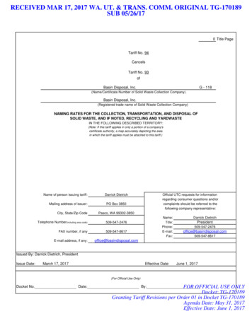
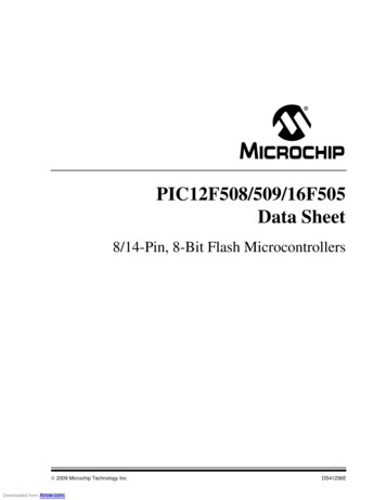
PIC12F508/509/16F5053.0ARCHITECTURAL OVERVIEWThe high performance of the PIC12F508/509/16F505devices can be attributed to a number of architecturalfeatures commonly found in RISC microprocessors.To begin with, the PIC12F508/509/16F505 devicesuse a Harvard architecture in which program and dataare accessed on separate buses. This improvesbandwidth over traditional von Neumann architectures where program and data are fetched on thesame bus. Separating program and data memory further allows instructions to be sized differently than the8-bit wide data word. Instruction opcodes are 12 bitswide, making it possible to have all single-wordinstructions. A 12-bit wide program memory accessbus fetches a 12-bit instruction in a single cycle. Atwo-stage pipeline overlaps fetch and execution ofinstructions. Consequently, all instructions (33)execute in a single cycle (200 ns @ 20 MHz, 1 μs @4 MHz) except for program branches.Table 3-1 below lists program memory (Flash) and datamemory (RAM) for the PIC12F508/509/16F505devices.TABLE 3-1:PIC12F508/509/16F505MEMORYThe PIC12F508/509/16F505 devices contain an 8-bitALU and working register. The ALU is a generalpurpose arithmetic unit. It performs arithmetic andBoolean functions between data in the working registerand any register file.The ALU is 8 bits wide and capable of addition, subtraction, shift and logical operations. Unless otherwisementioned, arithmetic operations are two’s complement in nature. In two-operand instructions, oneoperand is typically the W (working) register. The otheroperand is either a file register or an immediateconstant. In single operand instructions, the operand iseither the W register or a file register.The W register is an 8-bit working register used for ALUoperations. It is not an addressable register.Depending on the instruction executed, the ALU mayaffect the values of the Carry (C), Digit Carry (DC) andZero (Z) bits in the STATUS register. The C and DC bitsoperate as a borrow and digit borrow out bit, respectively, in subtraction. See the SUBWF and ADDWFinstructions for examples.Simplified block diagrams are shown in Figure 3-1 andFigure 3-2, with the corresponding pin described inTable 3-2 and Table 3-3.MemoryDeviceProgramDataPIC12F508512 x 1225 x 8PIC12F5091024 x 1241 x 8PIC16F5051024 x 1272 x 8The PIC12F508/509/16F505 devices can directly orindirectly address its register files and data memory. AllSpecial Function Registers (SFR), including the PC,are mapped in the data memory. The PIC12F508/509/16F505 devices have a highly orthogonal (symmetrical) instruction set that makes it possible to carry outany operation, on any register, using any addressingmode. This symmetrical nature and lack of “specialoptimal situations” make programming with thePIC12F508/509/16F505 devices simple, yet efficient.In addition, the learning curve is reduced significantly. 2009 Microchip Technology Inc.Downloaded from Arrow.com.DS41236E-page 11
PIC12F508/509/16F505FIGURE 3-1:PIC12F508/509 BLOCK DIAGRAM12Flash512 x 12 or1024 x 12ProgramMemory8Data BusProgram GP4/OSC2GP5/OSC1/CLKINRAM25 x 8 or41 x 8FileRegistersStack 1Stack 2Program 12BusRAM AddrGPIO9Addr MUXInstruction RegDirect Addr55-7IndirectAddrFSR RegStatus Reg83MUXDevice ResetTimerInstructionDecode andControlOSC1/CLKINOSC2TimingGenerationInternal RCOSCPower-onResetWatchdogTimerALU8W RegTimer0MCLRVDD, VSSDS41236E-page 12Downloaded from Arrow.com. 2009 Microchip Technology Inc.
PIC12F508/509/16F505TABLE 3-2:PIC12F508/509 PINOUT putTypeGP0TTLCMOS Bidirectional I/O pin. Can be software programmed for internalweak pull-up and wake-up from Sleep on pin change.ICSPDATSTCMOS In-Circuit Serial Programming data pin.GP1TTLCMOS Bidirectional I/O pin. Can be software programmed for internalweak pull-up and wake-up from Sleep on pin change.ICSPCLKSTCMOS In-Circuit Serial Programming clock pin.CMOS Bidirectional I/O pin.DescriptionGP2TTLT0CKIST—Clock input to TMR0.GP3TTL—Input pin. Can be software programmed for internal weakpull-up and wake-up from Sleep on pin change.MCLRST—Master Clear (Reset). When configured as MCLR, this pin isan active-low Reset to the device. Voltage on MCLR/VPP mustnot exceed VDD during normal device operation or the devicewill enter Programming mode. Weak pull-up always on ifconfigured as MCLR.—Programming voltage input.VPPHVGP4TTLOSC2—CMOS Bidirectional I/O pin.XTALGP5TTLOSC1XTAL—Oscillator crystal output. Connections to crystal or resonator inCrystal Oscillator mode (XT and LP modes only, GPIO in othermodes).CMOS Bidirectional I/O pin.Oscillator crystal input.CLKINST—External clock source input.VDDVDD—PPositive supply for logic and I/O pins.VSSVSS—PGround reference for logic and I/O pins.Legend: I Input, O Output, I/O Input/Output, P Power, — Not used, TTL TTL input,ST Schmitt Trigger input, HV High Voltage 2009 Microchip Technology Inc.Downloaded from Arrow.com.DS41236E-page 13
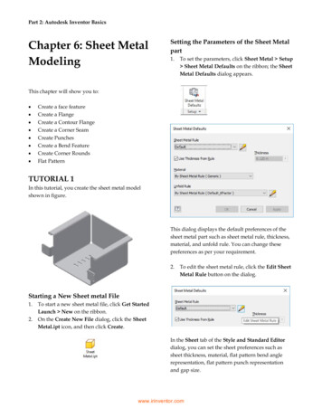
PIC12F508/509/16F505FIGURE 3-2:PIC16F505 BLOCK DIAGRAM12Flash1K x 12ProgramMemory8Data BusProgram C2/CLKOUTRB5/OSC1/CLKINRAM72 bytesFileRegistersStack 1Stack 2Program 12BusRAM Addr9PORTCAddr MUXInstruction RegDirect Addr55-7IndirectAddrFSR RegStatus Reg83Device ResetTimerInstructionDecode hdogTimerW RegInternal RCOSCTimer0MCLRVDD, VSSDS41236E-page 14Downloaded from Arrow.com. 2009 Microchip Technology Inc.
PIC12F508/509/16F505TABLE 3-3:PIC16F505 PINOUT TypeOutputTypeRB0TTLCMOS Bidirectional I/O pin. Can be software programmed for internalweak pull-up and wake-up from Sleep on pin change.ICSPDATSTCMOS In-Circuit Serial Programming data pin.RB1TTLCMOS Bidirectional I/O pin. Can be software programmed for internalweak pull-up and wake-up from Sleep on pin change.ICSPCLKSTCMOS In-Circuit Serial Programming clock pin.CMOS Bidirectional I/O pin.DescriptionRB2RB2TTLRB3/MCLR/VPPRB3TTL—Input port. Can be software programmed for internal weakpull-up and wake-up from Sleep on pin change.MCLRST—Master Clear (Reset). When configured as MCLR, this pin isan active-low Reset to the device. Voltage on MCLR/VPP mustnot exceed VDD during normal device operation or the devicewill enter Programming mode. Weak pull-up always on ifconfigured as MCLR.VPPHV—Programming voltage input.RB4TTLOSC2—XTALCLKOUT—CMOS In EXTRC and INTRC modes, the pin output can beconfigured for CLKOUT, which has 1/4 the frequency of OSC1and denotes the instruction cycle rate.RB5TTLRB4/OSC2/CLKOUTRB5/OSC1/CLKINCMOS Bidirectional I/O pin. Can be software programmed for internalweak pull-up and wake-up from Sleep on pin change.Oscillator crystal output. Connections to crystal or resonator inCrystal Oscillator mode (XT, HS and LP modes only).CMOS Bidirectional I/O pin.OSC1XTAL—Crystal input.CLKINST—External clock source input.RC0RC0TTLCMOS Bidirectional I/O pin.RC1RC1TTLCMOS Bidirectional I/O pin.RC2RC2TTLCMOS Bidirectional I/O pin.RC3RC3TTLCMOS Bidirectional I/O pin.RC4RC4TTLCMOS Bidirectional I/O pin.RC5/T0CKIRC5TTLCMOS Bidirectional I/O pin.T0CKIST—Clock input to TMR0.VDDVDD—PPositive supply for logic and I/O pins.VSSVSS—PGround reference for logic and I/O pins.Legend: I Input, O Output, I/O Input/Output, P Power, — Not used, TTL TTL input,ST Schmitt Trigger input, HV High Voltage 2009 Microchip Technology Inc.Downloaded from Arrow.com.DS41236E-page 15
PIC12F508/509/16F5053.1Clocking Scheme/InstructionCycle3.2Instruction Flow/PipeliningAn instruction cycle consists of four Q cycles (Q1, Q2,Q3 and Q4). The instruction fetch and execute arepipelined such that fetch takes one instruction cycle,while decode and execute take another instructioncycle. However, due to the pipelining, each instructioneffectively executes in one cycle. If an instructioncauses the PC to change (e.g., GOTO), then two cyclesare required to complete the instruction (Example 3-1).The clock input (OSC1/CLKIN pin) is internally dividedby four to generate four non-overlapping quadratureclocks, namely Q1, Q2, Q3 and Q4. Internally, the PCis incremented every Q1 and the instruction is fetchedfrom program memory and latched into the instructionregister in Q4. It is decoded and executed during thefollowing Q1 through Q4. The clocks and instructionexecution flow is shown in Figure 3-3 and Example 3-1.A fetch cycle begins with the PC incrementing in Q1.In the execution cycle, the fetched instruction is latchedinto the Instruction Register (IR) in cycle Q1. Thisinstruction is then decoded and executed during theQ2, Q3 and Q4 cycles. Data memory is read during Q2(operand read) and written during Q4 (destinationwrite).FIGURE 3-3:CLOCK/INSTRUCTION clockQ3Q4PCPCPC 1Fetch INST (PC)Execute INST (PC – 1)EXAMPLE 3-1:PC 2Fetch INST (PC 1)Execute INST (PC)Fetch INST (PC 2)Execute INST (PC 1)INSTRUCTION PIPELINE FLOW1. MOVLW 03H2. MOVWF PORTB3. CALLSUB 14. BSFPORTB, BIT1Fetch 1Execute 1Fetch 2Execute 2Fetch 3Execute 3Fetch 4FlushFetch SUB 1 Execute SUB 1All instructions are single cycle, except for any program branches. These take two cycles, since the fetch instructionis “flushed” from the pipeline, while the new instruction is being fetched and then executed.DS41236E-page 16Downloaded from Arrow.com. 2009 Microchip Technology Inc.
PIC12F508/509/16F5054.0MEMORY ORGANIZATIONThe PIC12F508/509/16F505 memories are organizedinto program memory and data memory. For deviceswith more than 512 bytes of program memory, a pagingscheme is used. Program memory pages are accessedusing one STATUS register bit. For the PIC12F509 andPIC16F505, with data memory register files of morethan 32 registers, a banking scheme is used. Datamemory banks are accessed using the File SelectRegister (FSR).FIGURE 4-1:PROGRAM MEMORY MAPAND STACK FOR THEPIC12F508/509PC 11:0 12CALL, RETLWStack Level 1Stack Level 2Reset Vector(1)Program Memory Organization forthe PIC12F508/509The PIC12F508 device has a 10-bit Program Counter(PC) and PIC12F509 has a 11-bit Program Counter(PC) capable of addressing a 2K x 12 program memoryspace.Only the first 512 x 12 (0000h-01FFh) for thePIC12F508, and 1K x 12 (0000h-03FFh) for thePIC12F509 are physically implemented (seeFigure 4-1). Accessing a location above theseboundaries will cause a wrap-around within the first512 x 12 space (PIC12F508) or 1K x 12 space(PIC12F509). The effective Reset vector is a 0000h(see Figure 4-1). Location 01FFh (PIC12F508) andlocation 03FFh (PIC12F509) contain the internalclock oscillator calibration value. This value shouldnever be overwritten.On-chip ProgramMemoryUser MemorySpace4.1Downloaded from Arrow.com.512 Word01FFh0200hOn-chip ProgramMemory1024 Word03FFh0400h7FFhNote 1: 2009 Microchip Technology Inc.0000hAddress 0000h becomes theeffective Reset vector. Location01FFh, 03FFh (PIC12F508,PIC12F509) contains the MOVLW XXinternal oscillator calibration value.DS41236E-page 17
PIC12F508/509/16F5054.2Program Memory OrganizationFor The PIC16F505The PIC16F505 device has a 11-bit Program Counter(PC) capable of addressing a 2K x 12 program memoryspace.The 1K x 12 (0000h-03FFh) for the PIC16F505 arephysically implemented. Refer to Figure 4-2.Accessing a location above this boundary will cause awrap-around within the first 1K x 12 space. Theeffective Reset vector is at 0000h (see Figure 4-2).Location 03FFh contains the internal oscillatorcalibration value. This value should never beoverwritten.FIGURE 4-2:PROGRAM MEMORY MAPAND STACK FOR THEPIC16F505PC 11:0 Stack Level 1Stack Level 2Reset Vector(1)Data Memory OrganizationData memory is composed of registers or bytes ofRAM. Therefore, data memory for a device is specifiedby its register file. The register file is divided into twofunctional groups: Special Function Registers (SFR)and General Purpose Registers (GPR).The Special Function Registers include the TMR0register, the Program Counter (PCL), the STATUSregister, the I/O registers (ports) and the File SelectRegister (FSR). In add
All Single-Cycle Instructions Except for Program Branches, which are Two-Cycle 12-Bit Wide Instructions . - DC 1000 ns instruction cycle Special Microcontroller Features: . All the tools are supported on IBM PC and compatible machines. 1.1 Applications Arrow.com. PIC12F508/509/16F505. PIC12F508/509/16F505