Transcription
4/8/10TCOM 500: Modern TelecommunicationsDr. Bernd-Peter ParisGeorge Mason UniversitySpring 2009MS in TelecommunicationsOutline Commonly used transmission media and theirproperties. Noise: the fundamental limiting factor in allcommunication systems. Path loss models for different transmissionmedia. Link budgets and transmission range. Distortion in transmission media.2ParisTCOM 500: Modern TelecommunicationsMS in Telecommunications1
4/8/10Context Purpose of a digital communication system: Replicate digital information available at the transmitter’slocation at the receiver’s location. Generally this implies connecting spatially separate locations. Same principle applies for communicating over time – storage ofinformation. The communications channel models the link connectingtransmitter and receiver. Channel models the degradation that the transmitted elsignalReceiverbitsTCOM 500: Modern TelecommunicationsMS in TelecommunicationsTRANSMISSION MEDIA4ParisTCOM 500: Modern TelecommunicationsMS in Telecommunications2
4/8/10Classification of Transmission d ee-spaceTCOM 500: Modern TelecommunicationsMS in TelecommunicationsTwisted Pair Cable Two electrical conductors – usually copper – eachcovered with insulating plastic. Used for baseband signaling – i.e., line codes. Signal is represented as the voltage between the conductors. Usually, one conductor is grounded; The other carries the signal.6ParisTCOM 500: Modern TelecommunicationsMS in Telecommunications3
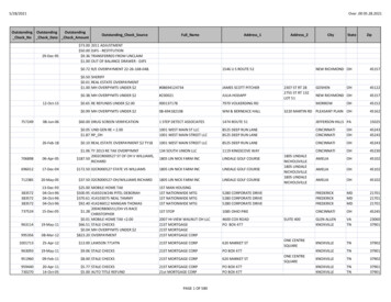
4/8/10Purpose of Twisting On a pair of parallel wires, the currents flowing through theconductors interact with each other. This can significantly reduce the flow of current, Especially at high frequencies. By twisting the wires, the direction of the induced currentchanges with every twist. The induced currents cancel each other.2. Current creates a magneticfield surrounding conductor.1. Current flows throughconductors in oppositedirections.3. Magnetic field induces acurrent in the other conductor.7ParisTCOM 500: Modern TelecommunicationsMS in TelecommunicationsShielded and Unshielded Twisted Pair UTP is most widely used. STP provides additional protection against externalelectromagnetic interference. Expensive and rarely used.8ParisTCOM 500: Modern TelecommunicationsMS in Telecommunications4
4/8/10Example: Category-5 UTP Standardized byANSI/TIA/EIA-568A. Includes four twistedpairs in a singlecable jacket. Typically, threetwists per inch. Wire thickness: 24gauge (0.205 mm²) Main use: 100Mb/sEthernet.9ParisTCOM 500: Modern TelecommunicationsMS in TelecommunicationsUTP Categories10ParisTCOM 500: Modern TelecommunicationsMS in Telecommunications5
4/8/10Connector UTP cables areterminated by 8P8C (8positions, 8 contacts)modular connectors. Often (incorrectly)referred to as RJ-45. Assignment of wires topins is specified byTIA/EIA-568-B.11ParisTCOM 500: Modern TelecommunicationsMS in TelecommunicationsCoaxial Cable Coax cable is an electricalcable with an inner conductor surrounded by a flexible,tubular insulating layer, surrounded by a tubularconducting shield. Coax cables are relativelyexpensive. Replaced largely by UTP fordata communications.12Paris Main benefit:the electromagnetic fieldcarrying the signal exists onlybetween the inner and outerconductors. Creates no interference. Very resilient to interference.TCOM 500: Modern TelecommunicationsMS in Telecommunications6
4/8/10Fiber Optic Cables An optical fiber is made up of the core (carrying the lightpulses), the cladding (reflecting thelight pulses back into the core)and the buffer coating (protectingthe core and cladding frommoisture, damage etc.). Main benefits: supports very high data rates upto 100Gb/s. With Wavelength divisionmultiplexing, single fiber cancarry up to 1600Gb/s. Low losses for long rangetransmission.13ParisTCOM 500: Modern TelecommunicationsMS in TelecommunicationsPropagation ModesMode Propagation of light relies onreflection of light towards thecore of the fiber. At boundary between claddingand fiber light is reflected aslong as incident angle is not toosteep. Snell’s law.14ParisMultimodeStep IndexSingleModeGradedIndexTCOM 500: Modern TelecommunicationsMS in Telecommunications7
4/8/10Propagation ModesRequires a highly focused beam at the source.15ParisTCOM 500: Modern TelecommunicationsMS in TelecommunicationsOptical Transmitter and ReceiverElectricalInterface Optical communicationschannels must interfacewith electrical equipment. Optical transmitter areLEDs or lasers. They convert an electricalsignal into light pulses.Optical Interface16Paris A photodiode convertsoptical signals toelectrical signals.TCOM 500: Modern TelecommunicationsMS in Telecommunications8
4/8/10NOISE IN COMMUNICATIONSYSTEMS17ParisTCOM 500: Modern TelecommunicationsMS in TelecommunicationsNoise Noise is the term used to describe the randomsignal that is added to the transmitted signal on itsway to the receiver. We distinguish noise from: Interference – either intentional or unintentionalperturbation from another transmitted signal. Distortion – the alteration the signal experiencesgenerally due to multiple-propagation paths. Noise is the fundamental limiting factor in anycommunication system.18ParisTCOM 500: Modern TelecommunicationsMS in Telecommunications9
4/8/10Thermal Noise In most communication systems, thermal noise is the mostimportant form of noise. Thermal noise is present in any conducting material and is due tothe random movement of electrons in the conductor. Thermal noise is random and is well modeled as following a Gaussiandistribution. Thermal noise is well modeled as covering the entire spectrumuniformly. White Noise Even though we “blame” the channel for introducing the noise, thereal culprit is the receiver. The signal is weakest just when it enters the receiver. After the receiver amplifies the signal, noise is no longer a concern. First amplifier is the critical component for controlling noise.19ParisTCOM 500: Modern TelecommunicationsMS in TelecommunicationsNoise Power The noise power can be predictedfrom thermodynamic principles.It depends on Temperature (T – measuredin Kelvin), Bandwith (B – in Hertz), and Boltzman’s constantk 1.38 10 23 (J/K).Noise power equals:PN kTBNoise power at room temperature(T 300K) per bandwidth B 1Hz:N0 4.14 10 21 W/Hz What is the Power of a signal? Power is the average strengthof the signal. Specifically,1 TP s(t) 2 dtT 0 Units: Watts (W) What is the Energy of asignal? Specifically,TE s(t) 2dt0 Units: Joules (J) 20ParisTCOM 500: Modern TelecommunicationsMS in Telecommunications10
4/8/10Noise Power in dBm It is very inconvenient to work with very small numbers, like N0.Instead it is customary to measure powers in a communication system on alogarithmic scale. Converting from linear scale to dB:XdB 10 log10(X).Converting from dB to linear scale:X 10(XdB/10)Minor problem: Only dimensionless quantities (i.e., with no units) can beconverted. The dB scale is used for this purpose. Solution: divide by reference value before converting to dB. Example: for powers it is common to divide by 1W (to obtain dBW) or by1mW (to obtain dBm). Illustration: We found N0 4.14 10 21 W/Hz. Divide by reference value1mW/Hz before conversion. Obtain -174dBm/Hz.21ParisTCOM 500: Modern TelecommunicationsMS in TelecommunicationsSignal-to-Noise Ratio If the channel can be modeled as an AWGNchannel, then the performance of communicationsystems is determined by the ratio of signalpower to noise power. AWGN – additive white Gaussian noise (modelsthermal noise) SNR – signal-to-noise ratio is the ratio ofreceived signal power and noise power.SNR Ps/(N0B). Most digital communication systems operate withSNRs in the range of 0dB to 20dB.22ParisTCOM 500: Modern TelecommunicationsMS in Telecommunications11
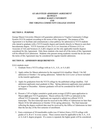
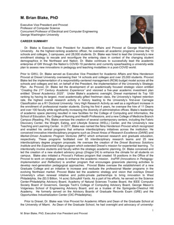
4/8/10Channel Capacity The important role of SNR is illustrated byShannon’s famous channel capacity theorem:Reliable communication is possible as long as thedata rate is less than the channel capacity C, whereC B log2(1 Ps/(N0B)). The theorem directly establishes a relationshipbetween sustainable data rate R and SNR. The theorem does not say how to do this.23ParisTCOM 500: Modern TelecommunicationsMS in TelecommunicationsChannel CapacityBandwidth B 1MHz10Capacity (Mb/s)86420ï1024Paris010SNR (dB)2030TCOM 500: Modern TelecommunicationsMS in Telecommunications12
4/8/10Exercise What is the thermal noise power for a channelof bandwidth 10MHz. Give your answer inWatts and dBm. If the received signal power is -95dBm, whatis the signal-to-noise ratio? What is the highest data rate that can besupported reliably under these circumstances?25ParisTCOM 500: Modern TelecommunicationsMS in TelecommunicationsPATH LOSS26ParisTCOM 500: Modern TelecommunicationsMS in Telecommunications13
4/8/10Path loss During propagation from transmitter to receiver, the signal becomesweaker. The loss in signal power is called path loss LP. The power of the received signal Pr is related to the power of thetransmitted signal Pt and the path loss:Pr Pt/LP. On a logarithmic scale we have the more convenient:Pr,dB Pt,dB – LP,dB. Recall: log(ab) log(a) log(b) and log(a/b) log(a) – log(b). Path loss depends mainly on the length of the link d but also on thefrequency f of the signal. Path loss models allow for translating minimum SNR requirementsinto maximum distances that can be supported.27ParisTCOM 500: Modern TelecommunicationsMS in TelecommunicationsPath Loss in Guided Media In guided media, path loss increases exponentially withdistance d. On a logarithmic scale: fixed dB loss per unit distance(e.g., 10dB/km). In addition, the path loss for electrical cables increasesfaster than linear with frequency. This is the result of the electromagnetic interactionbetween wires discussed earlier. Fiber-optic cables have by far the smallest path loss. Therefore, they are well suited for long-haul links.28ParisTCOM 500: Modern TelecommunicationsMS in Telecommunications14
4/8/10Path Loss in UTP and Coax CablesPath loss in dB per 100 meters of cableFrequency (MHz)Thin CoaxThick CoaxCategory 5 13.7022.0Source: http://www.westernextralite.com/resources.asp?key 24Question: An Ethernet transmitter sends signals 100MHz widesignals with power 26dBm over Cat-5 UTP. If the receiverrequires 20dB SNR, how long can the link be?29ParisTCOM 500: Modern TelecommunicationsMS in TelecommunicationsPath Loss in Optical Fibers Optical fibers havemuch lower path lossthan electrical cables. This allows for the useof much longer links. Original fibers hadlosses ofapproximately1000dB/km due toimpurities in the glass. Also, bandwidth andtherefore data rates aremuch higher.30ParisSource: NASATCOM 500: Modern TelecommunicationsMS in Telecommunications15
4/8/10Constructing Very Long Links The maximum tolerable path loss for a link is on the orderof 100dB. With higher path losses, the SNR becomes insufficient. To cover distances longer than what a single link cansupport, links are connected via repeaters. A repeater contains both a receiver and a transmitter. It retransmits a “fresh” copy of the signal it receives. Also called regenerators. Repeaters are expensive to install and maintain. Thus, thespacing between receivers should be as far as possible. Modern fiber-optic systems can work with repeater spacing ofhundreds of kilometers.31ParisTCOM 500: Modern TelecommunicationsMS in TelecommunicationsPath Loss in Wireless Links Over wireless links, the path loss increases atleast like the square of the distance, d2. If the direct line-of-sight path is obstructed, path losswill increase even faster. In general, path loss depends strongly on terraindetails and is not easily predicted. Wireless network operators spent a lot of effort on cellplanning. Identifying good location for base station to ensure goodcoverage over a wide terrain. Involves numerical prediction of path losses based on terrainmaps.32ParisTCOM 500: Modern TelecommunicationsMS in Telecommunications16
4/8/10Example: Free-Space Path Loss In free-space, a simple formula for path loss is known asFriis’s formula. It’s a good model for line-of-sight wireless links. Friis formula:LP (4π d f/c)2. c – speed of light (3 108 m/s) Friis formula in dB:Lp,dB 20 log10(d/1m) 20 log10(f/1Hz) – 147.55 dB Question: What is the path loss of a 1Km wireless if thecarrier frequency is 1GHz?33ParisTCOM 500: Modern TelecommunicationsMS in TelecommunicationsLink Budget Link budgets are used to determine if a given link will workor not. Link budgets always work on a logarithmic scale so that onlyadditions are required. A very simple budget:SNRdB Pt,dBm – LP,dB – N0,dBm/Hz – BdBHz. SNRdB – SNR at receiver, must be greater than required SNRPt,dBm – power of transmitted signal.N0,dBm/Hz – Noise power per 1Hz of bandwidth.BdBHz – Bandwidth of transmitted signal. More sophisticated link budgets account for additionalfactors, including antenna gains, implementation losses, orcable losses.34ParisTCOM 500: Modern TelecommunicationsMS in Telecommunications17
4/8/10Exercise Compute the SNR at the receiver if Transmitted power is 30dBm Free-space path loss with carrier frequency 1GHz Bandwidth 10MHz. If the SNR required at the receiver is 20dB,what is the maximum allowable path loss? What is the link distance for this path loss?35ParisTCOM 500: Modern TelecommunicationsMS in TelecommunicationsDISTORTION36ParisTCOM 500: Modern TelecommunicationsMS in Telecommunications18
4/8/10Distortion Distortion causes the shape of the transmitted signal tobe altered during transmission. Distortion can have different causes; Non-linear distortion Example: clipping of large amplitudes. Amplitude distortion Different parts of the spectrum of a signal experience differentattenuation (see path loss tables for cables). Delay distortion Different parts of the spectrum of a signal experience differentdelays. Multipath propagation Multiple “echoes” of the signal are received (see multi-modefibers) Can also be described as amplitude and delay distortion.37ParisTCOM 500: Modern TelecommunicationsMS in TelecommunicationsIllustration: Wireless Multipath1300125012001150Transmittery (m)1100Propagation betweentransmitter and receiverwill occur along manydifferent 550600650700x (m)750800850900950TCOM 500: Modern TelecommunicationsMS in Telecommunications19
4/8/10Multipath: Impulse Response 5Attenuation4x 1032100.811.21.4Delay (µs)1.61.820.811.21.4Delay (µs)1.61.82Phase Shift/!420 2 439Differentpropagationpaths arecharacterized bydifferent delays,attenuations, andphase shifts.ParisTCOM 500: Modern TelecommunicationsMS in TelecommunicationsMultipath: Frequency Response 78 80 Frequency Response (dB) 82 84 86 88 90 92 94 96 98 540Paris 4 3 2 101Frequency (MHz)2345 The attenuation of thechannel around thecarrier frequency(1GHz) variessignificantly withfrequency. Different part of thesignals spectrum willbe attenuateddifferently.TCOM 500: Modern TelecommunicationsMS in Telecommunications20
4/8/10Wideband PAM Signal d)1.51Amplitude0.50 0.5 1 1.5 200.511.522.5Time (µs)33.544.5 Transmitted signalhas approximatebandwidth 6MHz. Over this bandwidth,channel variessignificantly. Received signal isclearly distorted. Need an equalizerin the receiver.Real In-phaseImag Quadrature41ParisTCOM 500: Modern TelecommunicationsMS in TelecommunicationsWideband PAM SignalSignificantvariation inattenuation overthe band occupiedby the signal. 75 Frequency Response (dB) 80 85 90 95 100 542Paris 4 3 2 101Frequency (MHz)234TCOM 500: Modern TelecommunicationsMS in Telecommunications21
4/8/10Narrowband PAM Signal2 75TransmittedReal(Received)Imag(Received)1.5 80 Frequency Response (dB)1Amplitude0.50 0.5 85 90 95 1 1.5 100 2050100150Time (µs)200250300 5 4 3 2 101Frequency (MHz)234 Signal bandwidth approximately 60KHz. No distortion43ParisTCOM 500: Modern TelecommunicationsMS in Telecommunications22
George Mason University Spring 2009 MS in Telecommunications Outline . Coax cable is an electrical cable with an inner conductor surrounded by a flexible, tubular insulating layer, . channels must inter