Transcription
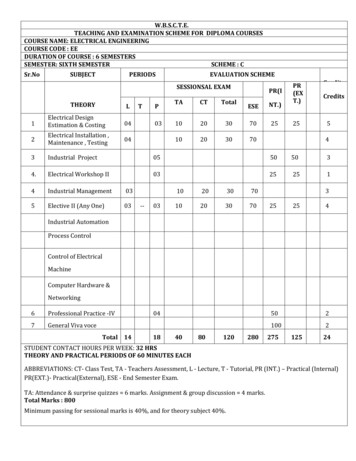
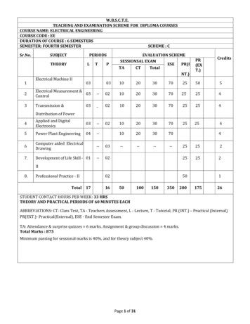
W.B.S.C.T.E.TEACHING AND EXAMINATION SCHEME FOR DIPLOMA COURSESCOURSE NAME: ELECTRICAL ENGINEERINGCOURSE CODE : EEDURATION OF COURSE : 6 SEMESTERSSEMESTER: FOURTH SEMESTERSCHEME : CSr.No.SUBJECTPERIODSTHEORYLTPEVALUATION SCHEMESESSIONSAL ditsElectrical Machine II1032Electrical Measurement &03Control--0210203070252543Transmission istribution of Power4Applied and DigitalElectronics03--5Power Plant Engineering04--6Computer aided ElectricalDrawing--037.Development of Life Skill - 01--42525202252520250II8.Professional Practice - IITotal 171650100150350200117526STUDENT CONTACT HOURS PER WEEK: 33 HRSTHEORY AND PRACTICAL PERIODS OF 60 MINUTES EACHABBREVIATIONS: CT- Class Test, TA - Teachers Assessment, L - Lecture, T - Tutorial, PR (INT.) – Practical (Internal)PR(EXT.)- Practical(External), ESE - End Semester Exam.TA: Attendance & surprise quizzes 6 marks. Assignment & group discussion 4 marks.Total Marks : 875Minimum passing for sessional marks is 40%, and for theory subject 40%.Page 1 of 31
West Bengal State Council of Technical Education(A Statutory Body under West Bengal Act XXI of 1995)Kolkata Karigori Bhavan, 2nd Floor, 110 S. N. Banerjee Road, Kolkata - 700 013.Name of the Subject : Electrical Machine – IICourse Code : EE/S4/EM IIDuration : One SemesterTeaching scheme :Theory: 3 Hrs./ WeekPractical: 3 Hrs./ WeekSemester : FourthMaximum Marks : 175Examination scheme :Mid Semester Exam:20 MarksAssignment & Quiz:10 MarksEnd Semester Exam: 70 MarksPractical:75 MarksCredit: 05Aim:Sl. No.1.2.Students will be able to analyze the performance of 3-phase and single phase A.C motorsand 3-phase Alternators both qualitatively and quantitatively.These machines are used widely in various Industries and Power plants. So knowledgegained by the students will be helpful in their job in industry and power plants.Objective:Sl. No.Student will be able to:1.Interpret the constructional details & working principles of A.C motors & generators.2.Test A.C motors & generators.3.Evaluate the performance of A.C machines by conducting different tests.4.Decide the suitability of AC machines for particular purpose.5.Write specifications of A.C motor & generators as required.6.Operate AC motor & generators as per requirement.Pre-Requisite:Sl. No.1.Three phase & single phase A.C fundamentals, Electromagnetism.2.Basic electronics engineering.Contents (Theory):Unit : 11. Three-Phase Induction Motor:1.1 Construction of 3-phase induction motor.1.2 Production of rotating magnetic field.1.3 Working principle of 3-phase induction motor.1.4 Concept of Synchronous Speed & Slip.1.5 Equation of rotor induced emf, current, frequency, reactance &impedance under standstill and running condition. (Numerical)1.6 Vector diagram (at no-load & running condition).1.7 Concept of Equivalent circuit (at no-load, at blocked rotor and atrunning condition).(No Numerical)1.8 Derivation of Torque equation, Starting torque, Running torque,Maximum torque and condition for maximum torque. (Numerical)1.9 Torque- Slip characteristics, Effect of change in rotor circuitresistance and supply voltage on Torque-Slip characteristics.1.10 Power stages in 3-phase induction motor and their relation,Losses, Efficiency. (Numerical)1.11 Starting methods of 3-phase induction motor by–a) Rotor resistance starter.b) Direct -On-Line starter.c) Autotransformer starter.Page 2 of 31Hrs./UnitMarks1424
d) Star-Delta starter (Manual & Automatic).(Numerical for allstarter)1.12 Speed control of 3-phase induction motor by –a) Changing supply frequency.b) Pole changing method.c) Changing Rotor circuit resistance & stator reactance.d) Changing supply voltage.1.13 Braking of 3-phase induction motor by –a) Plugging.b) Rheostatic method.c) Regenerative method.1.14 Cogging & Crawling (simple idea)1.15 Concept of Double cage rotor & Deep-bar rotor.1.16 Motor enclosures and specification as per I.S Code.1.17 Industrial applications of 3-phase induction motor.Unit : 22. Alternator:2.1 Construction of 3-phase alternator, Description of salient & nonsalient rotor.2.2 Methods of excitation systems of 3-phase alternator by –a) Static excitation.b) Brushless excitation.c) DC generator.2.3 Advantages of Stationary armature and Rotating field system.2.4 Armature winding – Single layer and multilayer, Concentrated andDistributed (Concept only).2.5 Derivation of E.M.F. equation of 3-phase alternator, Effect of Coilspan factor and Distribution factor on emf, Winding factor. (Numerical)2.6 Factors affecting the terminal voltage of alternator –a) Armature resistive dropb) Leakage reactance drop.c) Armature reaction at various p.f, concept of Synchronousreactance.2.7 Phasor diagrams of cylindrical rotor alternator at lagging, leading &unity p.f. loads.2.8 Voltage regulation of 3-phase alternator by – (Numerical)a) Synchronous Impedance Method.2.9 Open circuit characteristics, Short circuit characteristics of alternatorand determination of synchronous reactance.2.10 Active & Reactive power equations in terms of load angle at steadystate for non-salient pole alternator.2.11 Steady-state characteristics of Alternator –a) Terminal voltage vs. Load current, at different p.f,b) Field current vs. Load current at different p.f,c) Active & Reactive Power vs. load angle (non-salient alternator).2.12 Short circuit ratio (SCR) – concept & significance.2.13 Method of control of Active & Reactive Power of an alternator.2.14 Reasons & advantages of Parallel operation.2.15 Synchronization of two or more alternators by a) Three lamps method.b) Synchroscope.2.16 Parallel operation of (i) an alternator & infinite bus and (ii) Betweentwo alternators & Load sharing between them.(Numerical)1424Unit : 33. Synchronous Motor:3.1 Construction and working principle.3.2 Methods of starting by –a) An auxiliary motor.b) Damper winding.0808Page 3 of 31
3.3 Effect of variation of Load – Speed vs. Torque characteristics.3.4 Effect of variation of excitation at infinite bus (over and underexcitation) – V curves & inverted V-curves.3.5 Hunting, George’s phenomenon.3.6 Applications of synchronous motor, Synchronous condenser.Unit : 44. Single phase motors:4.1 Double-revolving field theory.4.2 Construction, Principle of operation and Applications of differenttypes of single-ph Induction motors –a) Split phase (resistance) type.b) Capacitor start type.c) Capacitor run type.d) Shaded pole motors.0508Unit : 55. Special Machines:5.1 Linear induction motor.5.2 Induction generator.5.3 A.C series motor.5.4 Reluctance Motor.07064870TotalPractical:Skills to be developed:Intellectual skills:1. Analytical skills.2. Identification skills.Motor skills:1. Measurement (of parameters) skills.2. Connection (of machine terminals) skills.List of Practical: (At least Eight Experiments are to be performed)1. a) To measure the slip of 3-phase induction motor by – (i) Stroboscopic method, (ii) Tachometer.b) To reverse the direction of rotation of 3-phase induction motor.2. To perform No-load test and Blocked-rotor test on 3-phase induction motor & draw the equivalentcircuit from the two tests.3. To perform the load test on 3-phase induction motor and to study the performancecharacteristics of the motor.4. To control the speed of 3-phase Induction motor by– (i) Frequency changing method, (ii) Polechanging method.5. To start a 3-phase Slip-ring induction motor by rotor resistance starter and determine the effectof the rotor resistance on the torque-speed curves of an induction motor.6. To observe the effect of excitation and speed on induced e.m.f of a 3-phase alternator and plotthe O.C.C. of the alternator.7. To find the percentage regulation of 3-phase alternator by synchronous impedance method atvarious power factor and load.8. To synchronise two 3-phase alternator for parallel operation by - a) Three lamp method, b)Synchroscope & to study the sharing of load between the alternators.Page 4 of 31
9. To list and explain various starting methods of 3-phase synchronous motor and applying any oneof them to start the synchronous motor. Plot V-curve & inverted V-curve of the same motor.10. To study the effect of capacitor on the starting and running condition of a single-phase Inductionmotor, and to determine the method of reversing the direction of rotation.Text books:Sl No. Titles of BookName of AuthorName of Publisher1.2.3.4.S.K.BhattacharyaDr. S.K.SenJ.B.GuptaM.G.SayT.M.H Publishing Co. Ltd.Khanna PublisherS.K.Kataria & Sons.C.B.S Publishers & yAshfaq HusainP.C.SenKhanna PublisherS.ChandP.H.I. Pvt. Ltd.Dhanpat Rai & Co.Wiley India10.Electrical MachinesElectrical MachineryElectrical MachinesThe performance and designofAlternatingCurrentmachinesElectrical MachineryElectrical Technology- Vol-IIElectrical MachinesElectrical tronicsElectrical Machines-IK.Krishna Reddy11.12.13.14.Electrical MachinesElectrical TechnologyElectrical MachinesElectrical MachinesNagrath & KothariH.CottonS. GhoshM.V.DeshpandeScitech Publication (India) Pvt.Ltd.T.M.HillC.B.S. Publisher New DelhiPearson PublisherPHI5.6.7.8.9.E X A M I N A T I O N S C H E M E (THEORITICAL)GROUPUNITONE OR TWO SENTENCE ANSWERQUESTIONSTO BESETA1, 4,512B2,3,611TO BEANSWEREDMARKSPERQUESTIONTOTALMARKSSUBJECTIVE QUESTIONSTO BESETFIVETWENTYONE1 X 20 20FOURTO BEANSWEREDFIVE, TAKING ATLEAST TWOFROM EACHGROUPMARKS PERQUESTIONTOTALMARKSTEN10 X 5 50Note: Paper-setter should take into account the marks which have beenallotted in each unit and set the paper accordingly so that all units get theimportance as allotted.E X A M I N A T I O N S C H E M E (SESSIONAL)1.Continuous Internal Assessment of 25 marks is to be carried out by the teachers throughout theFourth Semester. Distribution of marks: Performance of Job – 15, Notebook (Drawing) – 10.2.External Assessment of 50 marks shall be held at the end of the Fourth Semester on the entiresyllabus. One Experiment per student from any one of the above is to be performed. Experiment is to beset by lottery system. Distribution of marks: On spot job – 35, Viva-voce – 10.Page 5 of 31
West Bengal State Council of Technical Education(A Statutory Body under West Bengal Act XXI of 1995)Kolkata Karigori Bhavan, 2nd Floor, 110 S. N. Banerjee Road, Kolkata – 700 013.Name of the Course: Electrical Measurement & ControlCourse Code: EE/S4/EMCSemester: FourthDuration: one SemesterTeaching : 2hrs./weekMaximum Marks: 150Examination SchemeMid Semester Exam.:Assignment & Quiz:End Semester Exam.:Practical :20 Marks10 Marks70 Marks50 MarksCredit: 4(Four)Aim:Sl. No.1. Electrical power system, Electrical machine control, Industrial process control and many othersystems such as Biomedical, environmental, defence etc. nowadays use sophisticatedinstruments and their related systems for fast, accurate and reliable measurements,operations and control.2. Being Electrical Diploma Holders has a role of supervisor, Maintenance engineer and toassist in carrying out testing and R & D work in electrical, Industrial, Electronics andcommunication field.3He must understand the basics, facts, concepts and principles of various modern Instrumentsand control system.Objective:Sl. No. The students will be able to:1. Identify the components of Instrumentation system for processing given Input to get desiredOutput.2. Identify appropriate transducers/sensors for given application and to know how to use them.3. Identify basic signal conditioning circuit components for Instrumentation system in Industrialprocess, Electrical power system, Electrical machine operation, Measurement and control.4. Identify the digital instruments and display devices for various applications.5. Understand basic control system theory, stability concept6. Understand basics of P, PI, PD system and their application in real system.Pre-Requisite:Sl. No.1. Basic knowledge of Applied Electronics, Circuit theory, Electrical machines.Page 6 of 31
Unit: 1Contents (Theory)Hrs./Unit MarksTransducers:15201.1 Concept of Transducers1.2 Classification of TransducersPrimary and Secondary Transducers, Electrical and MechanicalTransducers, Analog and Digital Transducers, Active and passiveTransducers1.3 Construction, working principle and application (with diagram &explanation) of following transducers:1.3.1 RTD, Thermistor, Thermocouple.1.3.2 Potentiometer (various types)1.3.3 strain gauge (No derivation only formula)Types of strain gauges, Bridge circuit for strain gauge, application in load& Torque measurement1.3.4 Bourden tube, Bellows, Diaphragm.1.3.5 LVDT and RVDT, measurement for displacement.1.3.6 Capacitive transducers, Application in pressure measurement.1.3.7 Piezoelectric transducer, load cell.1.3.8 Contacting and non contacting tachometer, speed measurement1.3.9 Electromagnetic and turbine flow meter.Unit: 2Signal conditioning:2.1 Concept of signal conditioning.2.2 Block diagram of AC and DC signal conditioning and working.2.3. V to I converter, I to V converter, V to F converter.2.4 Instrumentation Amplifier.2.5 Filters - Types and frequency response (No derivation) and circuits.2.6 Multiplexing – Fundamentals, different types.0610Unit: 3Digital instruments and Display Devices3.1 Digital display devices (LED, seven segment only)3.2 Concept of 3 ½ ,4 ½ digit.3.3 Digital voltmeter- Integrating type, Successive approximation.3.4 Digital frequency meter.3.5 C.R.O. – Block diagram representation & operation, applications(observation & measurement of voltage, current, phase difference &frequency)Pilot Devices4.1 Pilot Devices - Definition of pilot devices, Function of pilot devices.List of different pilot devices.4.2 – Construction, working and applications of:Push Button, Limit Switch, Float Switch, Electromagnetic Relay, Pressureswitch, Thermostats plugging switch, Proximity switch.07100510Unit: 4Page 7 of 31
Unit: 5Control System:152048705.1 Introduction to control system, classification of control system,Feedback control system5.2 Properties of control system: idea on stability, steady state andtransient error. (no mathematical deduction)5.3 Control system components: Synchro, D.C Servomotor, A.C. Servomotor, A.C. Tachometer (only basic operating principle & constructionand diagram, no deduction)5.4 Concept of transfer function, poles and zeroes, transfer function offirst & second order system (no deduction), time response characteristicsof first and second order system to unit step excitation (no deduction).5.5 Block diagram representation of control system, Transfer functionfrom Block diagram reduction technique, Signal flow graph. Application ofMason gain formula (maximum two non touching loops).5.6 Stability concept: characteristic equation, Deciding stability from polezero concept, Routh criteria. (Numerical)5.7 Control action of a system with ON/OFF, P, PI, PD, PID controller,Practical application of these controllers (with block diagram only).TotalContents (Practical)Sl. No. Skills to be developed1. Intellectual Skills: i) Interpret resultsii) Calculate values of various components for given circuits.ii) Select Instruments2.Motor Skills:i) Connect the instruments properly.ii) Take accurate readings.iii) Draw phasor diagram and graphs.List of Laboratory Experiments:Sl. No. Laboratory Experiments: (At least eight experiments are to be performed)1.To measure Linear displacement by LVDT & plot characteristics.2.To measure displacement by Strain gauge & plot characteristics.3.To measure temperature by pt-100, thermistor and thermocouple along with simpleresistance bridge.4.To plot characteristics of potentiometer and observe the loading effect on output ofpotentiometer.5.To study the following signal conditioning circuits and observe and plot the output(i)V to I Converter, (ii) I to V Converter, (iii) V to F Converter using Op-AMP 741.6.To measure angular speed by contact type, non- contact type tachometer, DigitalTachometer, Proximity sensor.7.To plot frequency response of Active filters (any two):- I) Low pass filter II)High pass filterIII) Band pass filter Iv) Band stop filters.Page 8 of 31
8.To study the principle of operation and connection of pilot devices like – Push Button Switch,Limit Switch, Selector switch, Pressure switch, Float switch.9.To measure voltage, current and Phase difference and Frequency using CRO.10.To study open loop control of any physical control system and study of closed loop control ofthe same system using P, PI and PID controller.11.To study the position control system using servomotor.12.To study the operation of an instrumentation amplifier using OPAMP.Text BooksSl No.Name of Authors1.A.K.Sawhney2.Titles of the BookName of PublisherDhanpat Rai & Co.H.S.KalsiElectrical and Electronics Measurementand InstrumentationElectronic Instrumentation3.D.PatranabisPrinciples of Industrial InstrumentationTata McGraw Hill4.A.K.SawhneyProcess control & instrumentationDhanpat Rai & Co.5.Donald P. EckmanIndustrial InstrumentationWiley Eastern Ltd.6.B.C.KuoAutomated Control SystemsWiley India7.Nagrath GopalControl System EngineeringNew Age International8.Control System EngineeringScitech Publication (India) ltd.Control of Electrical MachinesNew Age International10.R. Anandanatarajan,P.Ramesh BabuS.K. BhattachryaBrijinder SinghK.Lal KishorePearson11.M.GopalElectronic Measurement andInstrumentationControl Systems Principles and Design9.Tata McGraw HillMcGraw Hill Education (India)Pvt.LtdE X A M I N A T I O N S C H E M E (THEORITICAL)GROUPUNITA1B2,3,4C5ONE OR TWO SENTENCEANSWER QUESTIONSSUBJECTIVE QUESTIONSTO BE TO BEMARKS TOTAL TO BETO BEMARKS TOTALSET ANSWERPERMARKS SETANSWEREPERMARKSEDQUESTIODQUESTIONN7FOUR FIVE, TAKINGTWENTYONE1 X 20AT LEASTTEN10 X 5 6 20 THRE ONE FROM50E EACH GROUP7FOURNote: Paper-setter should take into account the marks which have beenallotted in each unit and set the paper accordingly so that all units get theimportance as allotted.Page 9 of 31
E X A M I N A T I O N S C H E M E (SESSIONAL)1. Continuous Internal Assessment of 25 marks is to be carried out by the teachersthroughout the Fourth Semester. Distribution of marks: Performance of Job - 15, Notebook- 10.2. External Assessment of 25 marks shall be held at the end of the Fourth Semester on theentire syllabus. One Experiment per student from any one of the above is to be performed.Experiment is to be set by lottery system. Distribution of marks: On spot job - 15, Vivavoce - 10.Page 10 of 31
West Bengal State Council of Technical Education(A Statutory Body under West Bengal Act XXI of 1995)Kolkata Karigori Bhavan, 2nd Floor, 110 S. N. Banerjee Road, Kolkata - 700 013.Name of the Subject: Transmission and Distribution of PowerSubject Code: EE/S4/TDPSemester: FOURTHDuration: one SemesterMaximum Marks: 150Teaching SchemeExamination SchemeTheory: 3 Hrs./WeekMid Semester Exam.: 20MarksTutorial: nilAssignment & Quiz: 10MarksPractical: 2 Hrs./WeekEnd Semester Exam.: 70MarksCredit: 04Practical Exam.:50MarksAim:Sl. No.Electrical diploma pass outs should know systems for electrical energy transmission &1.distribution. They also will be able to identify various components & their functions.They will be able to measure system performance. They will be able to deal with various2.aspects of transmission and distribution system at different stages including erection andmaintenance. Hence he should be well acquainted with the materials required and themethods employed for erection and maintenance.On completion the study of transmission & distribution, he/she will beable to work as technician/supervisor in power industry, manufacturing industry & publicutilities.Objective:Sl.Student will be able to:No.Interpret various types of transmission & distribution systems.1.2.Identify various components & Know their functions.3.Calculate voltage regulation & efficiency of transmission system.4.Calculate voltage drop of distribution system.Pre-Requisite:Sl. No.Basic Electrical Engineering.1.3.2.Unit: 1Electrical Power GenerationContents (Theory)Basics Of Transmission:Hrs./Unit04Marks412161.1 Layout of a Power System by single line concept.1.2 Concept of Primary & Secondary transmission &distribution.1.3 Advantages and limitations of using high voltage forpower transmission.1.4 Comparison between AC & DC power transmissionsystems.1.5 Kelvin’s laws for the economic choice of conductorsize – related problem.Unit: 2Transmission Line Components:2.1 Main components of Overhead lines (names &functions only).2.2 Types of conductors-Copper, Aluminum & statetheir trade names.2.3 Solid, Stranded & bundled conductors.Page 11 of 31
2.4 types of supports – RCC/PCC poles, steel tower2.5 Comparison between single circuit and double circuitdesign2.6 conception of ground wire.2.7 Line insulators – requirements, types, and fieldofapplications.2.8 failure of insulators, creepage distance (definition &significance only)2.9 Distribution of potential over a string of threesuspension insulators. --- Problems.2.10 Concept of string efficiency, Methods ofimproving string efficiency. ---- Problems.2.11 Corona – corona formation, advantages &disadvantages, factors affecting corona, importantterms related to corona.2.12 Calculation of Span length & sagCalculation , effect of wind pressure, temperature andice deposition----- Problems.2.13 Stringing chart and its uses.2.14 Spacing of conductors, length of span,Unit: 3Unit: 4Unit:5Relevant I.E. Rules.Tansmission Line Parameters:3.1 R,L & C of 1-ph & 3-ph transmission line & theireffects on line.( No deduction and Problems)3.2 Skin effect, proximity effect & Ferranti effect.3.3 Concept of transposition of conductors &necessity.Underground Cables:4.1 Classification of cables and Comparison withoverhead lines.4.2 Cable construction.4.3 Description of (i) PVC, (ii) PILC (iii) FRLS (FireRetardant Low Smoke), (iv) XLPE cables & (v) Gasfilled (SF6) cables4.4 Cable Rating and De-rating factor.4.5 Cable layingPerformance Of Transmission Line:5.1 Classification of transmission lines.5.2 Losses, Efficiency & Regulation of line.5.3 Performance of single phase short transmissionline(Numerical based on it )5.4 Effect of load power factor on performance.0330470915035Power Factor Improvement Using Static condenser andSynchronous condenser – related problems.Unit:65.5 Medium transmission lines-End condenser,Nominal T & Nominal Pi Network with vectordiagram.---- no problem.Extra High Voltage Transmission:6.1 EHVAC Transmission, Reasons for adoption &limitations.6.2 Regional Grid System (Conception only).6.3 Concept about FACTS and its applications.6.4 HVDC Transmission – Advantages, Limitations.6.5 Discussion on few HVDC system in Indianscenario.Page 12 of 31
Unit:7Unit:8Components of Distribution System:7.1 Introduction.7.2 Classification of distribution system.7.3 A.C distribution.7.4 Connection schemes of distribution system.7.5 Requirements of Distribution systems.7.6 Design consideration.7.7 A.C. distribution calculations.7.8 Methods of solving A.C.-1 phase & 3 Ø -phaseconnection ( balanced ) distribution system.( Numericals based on 1-ph & 3-ph balanceddistribution system)Substations:8.1 Introduction.8.2 Classification of indoor & outdoor sub-stations.8.3 Advantages & Disadvantages.8.4 Selection & location of site.8.5 Main connection schemes.8.6 Equipments and circuit element of substations –their symbols & function.8.6.1 Bus bar’s material, types in detail.8.6.2 Connection diagram and layout of sub-stationswith proper notation.Total08120584870Contents (Practical)Sl. No.1.Skills to be developedIntellectual Skills:1.1 Identification & selection of components.1.2 Making proper connections2.Motor Skills:2.1 Ability to measure various parameters.2.2 Ability to follow standard test procedures.LIST OF EXPERIMENTS : (At least Eight Experiments are to be performed)3.1 To demonstrate the improvement of P.f. using static condenser.3.2 To demonstrate various system faults by D.C. network analyzer.3.3 To study active and reactive power flow through transmission lines.3.4 To study the supply system of 6.6 KV/400V sub-station to a housing complex usingslides/model.3.5 To study various types of turbine used in Power station using slides/models.3.6 To study different types of excitation system for alternator using slides/models.3.7 To study different kinds of insulators (Insulators are required to be available inlaboratory)3.8 To study PILC, PVC, FRLS and XLPE cables. (Cables are required to be available inlaboratory)3.9 To measure Solar Radiation with the help of Pyranometer.3.10 To demonstrate the photo voltaic system used in street lighting – PV module, CCU,Battery, CFL.3.11 To study power generation by wind power – using model / slides.Page 13 of 31
Text Books:Name of AuthorsV. K. MehtaTitle of the BookPrinciples of power systemSoniGupta-BhatnagarEditionA Course in electrical powerTransmission & distributionof electrical energyPower System AnalysisTransmission & Distribution ofPowerPower System Operation andControlGeneration, Transmission andUtilization of Electric PowerElectrical Power SystemJ. B. GuptaNagsarkar & SukhijaTarlok Singh.Dr. K.Uma RaoA. T. StarrC.L.Wadhwa.Name of the PublisherS. Chand & CompanyDhanpat RaiS.K. Kataria & Sons.Oxford University PressS.K. Kataria & Sons.Wiley-IndiaPitmanWiley Eastern LtdE X A M I N A T I O N S C H E M E (THEORITICAL)GROUPUNITONE OR TWO SENTENCE ANSWERQUESTIONSTO BESETA1, 2, 3,412B5,6,7,812TO BEANSWEREDMARKSPERQUESTIONTOTALMARKSSUBJECTIVE QUESTIONSTO BESETFOURTWENTYONE1 X 20 20FIVETO BEANSWEREDFIVE taking atleast THREEfrom eachGroupMARKS PERQUESTIONTOTALMARKSTEN10 X 5 50Note: Paper-setter should take into account the marks which have beenallotted in each unit and set the paper accordingly so that all units get theimportance as allotted.E X A M I N A T I O N S C H E M E (SESSIONAL)1.2.Continuous Internal Assessment of 25 marks is to be carried out by the teachers throughout theFourth Semester. Distribution of marks: Performance of Job – 15, Notebook – 10.External Assessment of 25 marks shall be held at the end of the Fifth Semester on the entire syllabus.One Experiment per student from any one of the above is to be performed. Experiment is to be set bylottery system. Distribution of marks: On spot job – 15, Viva-voce – 10.Page 14 of 31
West Bengal State Council of Technical Education(A Statutory Body under West Bengal Act XXI of 1995)Kolkata Karigori Bhavan, 2nd Floor, 110 S. N. Banerjee Road, Kolkata - 700 013.Name of the course : Applied and Digital ElectronicsCourse Code : EE/S4/ADESemester : FourthDuration : One SemesterMaximum Marks : 150Teaching scheme :Examination scheme :Theory: 3 Hrs./ WeekMid Semester Exam:20 MarksPractical: 2 Hrs./ WeekAssignment & Quiz:10 MarksEnd Semester Exam:70 MarksPractical:50 MarksCredit: 04Aim:Sl. No.1.It intends to teach the operating principles and applications of different types of Amplifiersand Oscillators.2.The subject also includes the Basic Digital logic circuits and their applications, D/A & A/Dconverters etc.2.Understanding of the subject will provide skill to the students for trouble shooting & testing ofsome basic Amplifier circuits, Oscillator circuits and Digital logic circuits.Objective:Sl. No.Student will be able to:1.Illustrate the Amplifier circuits and Oscillator circuits.2.Describe the Digital logic circuits, Flip-flop, Counter, Register, D/A & A/D converter.3.Test the Amplifier circuits, Oscillator circuits and Digital logic circuits.Pre-Requisite:1.Knowledge of Basic Electronics.2.Knowledge of Analog & Digital Electronics.Page 15 of 31
Contents (Theory):Unit : 11. Amplifiers:Hrs./UnitMarks101608141. Power Amplifiers:1.1.1 Classification of power amplifiers – Class-A, Class-B,Class-AB, Class-C operation, Advantage & disadvantages ofthese amplifiers.1.1.2 a) Operation of Class-A Push-pull amplifier.b) Operation of Class-B Push-pull amplifier.c) Operation of Class-AB Push-pull amplifier.1.2 FET Amplifier:1.2.1 Biasing methods of FET.1.2.2 le1.2.3 Introduction to MOSFET – Types ofconstruction, working principle and applications.&MOSFET,1.2.4 CMOS – construction and application.frequency.1.3 Operational Amplifier:1.3.1 Basic differential amplifier circuit using BJT.1.3.2 Pin diagram of OPAMP IC741& functions of each pin.Definition of offset voltage, input bias current, input offsetcurrent, differential mode gain, CMRR, slew rate1.3.3 OPAMP as Non-inverting and Inverting amplifier, Adder,Subtractor, Integrator, Differentiator, Unity Gain Buffer, SchmittTrigger, Zero Crossing Detector.1.3.4 Instrumentation amplifier – Operating principle usingOPAMP, Applications.Unit : 22. Feedback Amplifiers & Oscillators:2.1 Theory of Positive & Negative feedback.2.2 Types of negative feedback amplifiers –shunt-voltage,series-voltage, shunt-current, series-current feedback.2.3 Introduction to oscillator, Block diagram of sine waveoscillator, requirement of oscillation, Barkhausen criterion.2.4 Wien bridge oscillator, Colpitt oscillator – operating principle,frequency of oscillation.Page 16 of 31
Unit : 33. Boolean Algebra & Combinational Logic Circuits:08141014121248703.1 Number Systems – Decimal, Binary, Octal, Hexadecimal,BCD number system & their inter-conversion.3.2 Symbolic representation & Truth tables for logic gates NOT, OR, AND, NAND, NOR, XNOR, XOR.3.3 Rules & laws of Boolean algebra, Demorgan’s Theorems.3.4 Max. term & Min. term, Simplification of Boolean expressionusing karnaugh map (upto 4 variable).3.5 Realisation of Boolean expression with Logic gates.3.6 Half adder, Full adder, Half subtractor, Full subtractor, ParityGenerator and checker, Digital comparator3.7 Code converter,DemultiplexerUnit : 4Encoder,Decoder,Multiplexer,4. Sequential Logic Circuits:4.1 Flip-flops – RS, D, T, JK, JK Master Slave Flip Flops usingbasic gates, preset and clear signals
5 Power Plant Engineering 04 -- 10 20 30 70 4 6 Computer aided Electrical . Text books: Sl No. Titles of Book Name of Author Name of Publisher 1. Electrical Machines S.K.Bhattacharya T.M.H Publishing Co. Ltd. 2. Electrical Machinery Dr. S.K.Sen Khanna Publisher 3. Electrical Machines J.B.Gupta S.K.Kataria & Sons.


![[SEM] Structural Equation Modeling - Stata](/img/31/sem.jpg)
