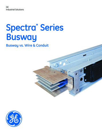
Transcription
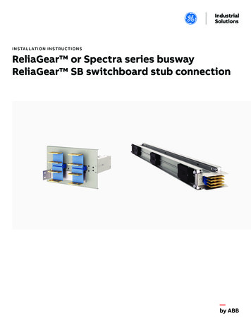
I N S TA L L AT I O N I N S T R U C T I O N SReliaGear or Spectra series buswayReliaGear SB switchboard stub connection
I N S TA L L AT I O N I N S T R U C T I O N S3Table of contents04 Before installation05Storage precautions06– 08Installation for top feed10Installation for bottom feed
R E L I A G E A R O R S P E C T R A S E R I E S B U S WAY R E L I A G E A R S B S W I T C H B O A R D S T U B C O N N E C T I O N4Before CTIONSDANGER: DO NOT perform any installationprocedures described below without de-energizingthe Busway/Switchboard, ensuring the main circuitbreaker device is OFF, AND appropriate Lockout/Tagout (LOTO) procedures are performed.Before any installation work is performed, study alldrawings furnished by the supplier for theinstallation. These include arrangement drawings(front, end, and plan view), connection diagrams,and schedule of equipment. Any material exteriorto the equipment that may be required to meet anylocal codes is not furnished.
I N S TA L L AT I O N I N S T R U C T I O N S5Storage precautionsDANGERBefore storing, unpack sufficiently to check thebusway for possible concealed damage resultingfrom shipping and handling. If damage hasoccurred, notify the shipper immediately. If thebusway is free of damage, restore the packing untilready for installation.Store indoors in a clean, dry area, preferably closeto the installation points.Protect the busway from mechanical damage andany contact with or exposure to corrosive fumes,liquids, salts, or concrete.WARNINGFailure to store and protect the busway properlycan cause serious damage and will void theCAUTIONwarranty.NOTICESAFETYINSTRUCTIONSNOTICE: No busway, includingoutdoor rated, is weatherproof untilcompletely and properly installed
6R E L I A G E A R O R S P E C T R A S E R I E S B U S WAY R E L I A G E A R S B S W I T C H B O A R D S T U B C O N N E C T I O NInstallation for top feed—01 Location of removableshipping screws(front top width postremoved for clarity)—02 Removingshipping plateUnpacking and inspecting the unit Inspect the ReliaGear SB switchboard buswayconnection and ensure that there is no noticeableshipping damage that could interfere with theoperation of the device. Contact surfaces mustbe clean. Do NOT attempt to polish tarnishedcontact surfaces. Check that joint insulators are not damaged orcracked and are firmly in place. Megaohm test the piece before installation. Consult DEH40087 Spectra series plug-in andfeeder busway or 1VAL098202-MB ReliaGearbusway, 1VAL088301-MB ReliaGear SBswitchboard Installation, Operations, andMaintenance manual for additional reference.Remove shipping cover plate Remove all Grade-5 ¼”-20 bolts and gasketedwashers (Figure2) from the top of the shippingplate (Note: the quantity will vary depending onthe width of the switchboard and flangeconnection). Take off the removable shipping cover plate asshown in Figure 2 and dispose of accordingly. RemoveDANGER any remaining gasket material or residueto ensure clean surface for new Remove shipping screws in switchboard Remove the top cover of the switchboard asshown in Figure 1. Remove the (2) 10-32 shipping screws on theintegrated Spectra busway joint or ReliaGearbusway as shown in Figure 1 and dispose ofscrews accordingly.CAUTIONCAUTION: Application of gasketmaterial is required for NEMA-3Rconstructions. Failure to applygasket could result in serious injuryand equipment TICE: Gasket material is notrequired for non NEMA-3Rapplications. Gasket material willstill be supplied to provide a morerobust design if desired1/4" -20 bolts andgasketed washersRemovable shipping plateSwitchboard top cover(2) Shipping screwsJoint Guard bolt(s)—01Clean surface for new gasket—02
I N S TA L L AT I O N I N S T R U C T I O N S—03 Gasket locatordimples diagram—04 Application of Gasket7Preparing/applying gasket material (NEMA 3Rconstruction only) Inspect the top of the switchboard to identify thegasket locator dimples as shown in Figure 3.These will be used to align the gasket on the topof the switchboard. Apply the gasket to the clean surface of theswitchboard using the gasket locator dimplesshown in Figure 4.Rear of switchboardLocation dimplesFront of switchboardHorizontal gasketVertical gasket (7.75")—04—03Gasket locator dimples for N3R construction Cut the supplied gasket into (4) total strips – (2)shorter to be applied in the vertical direction and(2) longer to be applied in the horizontal direction(Figure 4) The length of the horizontal (longer) pieces ofgasket will vary depending on the ReliaGearbusway material and amperage rating. Cut thehorizontal strips per Table 1. The vertical stripsmust always be cut to 7.75”7.75"NOTICESAFETYINSTRUCTIONSNOTICE: The phase side of theintegrated busway connection insidethe switchboard will always befacing the front of the switchboard. Slightly loosen the ½” Joint Guard bolt on theintegrated busway joint inside the switchboard(FigureDANGER1)—Table 1: Gasket length chartVerticallengthInstalling Reliagear switchboard buswayDANGERconnection to switchboard Establish the bus bar phase sequence (Ø side isWARNINGlabeled) that determines how the buswayconnection should be installed, so that correctCAUTIONphasing is maintainedHorizontallengthAL BuswayCU STRUCTIONSWARNING: The housing-ground sideplates must pass between theoutside insulator and the jointground side plate to avoid a phaseto-ground short circuit.
8R E L I A G E A R O R S P E C T R A S E R I E S B U S WAY R E L I A G E A R S B S W I T C H B O A R D S T U B C O N N E C T I O N—05 Busbars interweavingwith the joint Raise or lower the busway so that the bus barsinterweave the insulators as shown in Figure 5.The busway should be adjusted until the flangemounting plate is flush against the switchboard.—06 Exploded view ofbus stub installationShipping screws—05InsulatorJoint-Ground side plateHousing-Side ground plateBus stub connection(example)¹/4"-20 Bolts withgasketed washersGasket materialSupplied cage nuts—06DANGERWARNINGCAUTION Inspect the busway run for straightness in allplanes and make any adjustments necessary forgood alignment.CAUTION: The bus stub connection must beexternally supported from the switchboard. Failureto do so may cause damage to equipment or ETYINSTRUCTIONSNOTICESAFETYINSTRUCTIONSDANGER Tighten the Joint Guard torque-indicating boltto 50 ft-lb (68 N-m) using a ¾” or 19-mm sockettorque wrench set. The color indicator shouldturn fully black and can be viewed periodically toensure proper torque. Bolt down the Busway flange mounting plate withsupplied ¼”-20 bolts with gasketed washers(Figure 6). Torque these screws to 4 ft-lb (5.5 N-m) into thesupplied cage nuts.WARNING: Failure to use gasketedwashers in NEMA-3R applicationswill result in major equipmentdamage or injury.CAUTION: Failure to tighten bolts torequired torque could result in majorequipment damage or injury.NOTICEReinstall top coverSAFETY INSTRUCTIONSReinstall the top cover of the switchboard with¼”-20 thread rolling screws. Torque the ¼”-20 thread rolling screws to 4 ft-lb(5.5 N-m).Continue with general installation instructions Continue with general installations instructionsfor Spectra Busway (DEH40087) or1VAL098202-MB ReliaGear Busway, and1VAL088301-MB ReliaGear SB SwitchboardInstallation, Operations, and Maintenance manual
I N S TA L L AT I O N I N S T R U C T I O N S9
10R E L I A G E A R O R S P E C T R A S E R I E S B U S WAY R E L I A G E A R S B S W I T C H B O A R D S T U B C O N N E C T I O NInstallation for bottom feedUnpacking and inspecting the unit Inspect the ReliaGear SB switchboard buswayconnection and ensure that there is no noticeableshipping damage that could interfere with theoperation of the device. Contact surfaces mustbe clean. Do NOT attempt to polish tarnishedcontact surfaces. Check that joint insulators are not damaged orcracked and are firmly in place. Megaohm test the piece before installation. Consult DEH40087 Spectra series plug-in or1VAL098202-MB ReliaGear busway, and feederbusway and 1VAL088301-MB ReliaGear SBswitchboard Installation, Operations, andMaintenance manual for additional reference.Remove shipping screws in switchboard Remove the top cover of the switchboard asshown in Figure 1. Remove the (2) 10-32 shipping screws on theintegrated Spectra or ReliaGear busway joint asshown in Figure 1 and dispose of screwsaccordingly.
—ABB Inc.305 Gregson DriveCary, NC 27511 USAabb.com\contactsabb.com/lowvoltageThe information contained in this document is for generalinformation purposes only. While ABB strives to keep theinformation up to date and correct, it makes norepresentations or warranties of any kind, express orimplied, about the completeness, accuracy, reliability,suitability or availability with respect to the information,products, services, or related graphics contained in thedocument for any purpose. Any reliance placed on suchinformation is therefore strictly at your own risk. ABBreserves the right to discontinue any product or serviceat any time. Copyright 2021 ABB. All rights reserved.1VAL098202-HT Rev A October 2021GE is a trademark of GE.Manufactured by ABB Ltd under licensefrom General Electric Company.
Consult DEH40087 Spectra series plug-in or 1VAL098202-MB ReliaGear busway, and feeder busway and 1VAL088301-MB ReliaGear SB switchboard Installation, Operations, and Maintenance manual for additional reference. Remove shipping screws in switchboard Remove the top cover of the switchboard as shown in Figure 1.