Transcription
Materials and Structures (2022) 123456789().,-volV)(0123456789().,-volV)ORIGINAL ARTICLESplitting capacity of Eucalyptus globulus beams loadedperpendicular to the grain by connectionsAlmudena Majano-Majano . Antonio José Lara-BocanegraJosé Xavier . Manuel Guaita.Received: 18 December 2021 / Accepted: 11 May 2022 / Published online: 5 June 2022Ó The Author(s) 2022Abstract In timber structures, knowledge of thesplitting capacity of beams loaded perpendicular to thegrain by dowel-type connections is of primordialimportance since brittle failure can occur. In thepresent work, single- and double-dowel-type connections following different loaded edged distancearrangements are experimentally investigated toderive the splitting behaviour of Eucalyptus globulusL., which is a hardwood species of increasing interestfor structural use due to its high mechanical performance, fast growth, and good natural durability. Thecorrelation of experimental failure loads with thosetheoretically predicted by the expression included inA. Majano-Majano (&) A. J. Lara-BocanegraDepartment of Building Structures and Physics, School ofArchitecture, Universidad Politécnica de Madrid, Avda.Juan de Herrera, 4, 28040 Madrid, Spaine-mail: almudena.majano@upm.esA. J. Lara-Bocanegrae-mail: antoniojose.lara@upm.esJ. XavierUNIDEMI, Department of Mechanical and IndustrialEngineering, Faculty of Sciences and Technology, NOVAUniversity of Lisbon, 2928-516 Caparica, Portugale-mail: jmc.xavier@fct.unl.ptM. GuaitaDepartment of Agroforestry Engineering, University ofSantiago de Compostela, Calle Benigno Ledo,27002 Lugo, Spaine-mail: m.guaita@usc.esEurocode 5 and by eight analytical models based on anenergetic approach is discussed. Most of the analyticalmodels studied overpredict the splitting capacity.However, the code splitting expression, derived fromsoftwoods, proves to be very conservative in predicting the eucalyptus splitting failure load.Keywords Dowel joint Hardwood Blue gum Fracture energy Analytical model1 IntroductionNowadays, there is growing environmental awarenessand increasing demands for sustainability, in responseto which wood is established as one of the mostsuitable materials for building as a natural andrenewable resource.Although the vast majority of products used intimber engineering are made of softwoods, hardwoodspecies are gaining increasing attention for structuralapplications in the European market. This is mainlydue to the large stocks of structurally unused hardwood resources in Central and Southern Europe, to theshortage of softwoods and consequent higher costs,and to continuous changes in reforestation policiestoward hardwoods due to the greater suitability ofseveral broadleaf species for soil and climate conditions [1]. This interest is demonstrated by emerging
147 Page 2 of 17hardwood products, mainly glued laminated products[e.g., 2–4].In this regard, Eucalyptus globulus Labill (alsoknown as southern blue gum) stands out as a highperformance hardwood of significant interest, due toits fast growth, high mechanical properties, and goodnatural durability. Recently, there has been increasingindustrial and institutional interest driving scientificresearch on E. globulus in different fields, such assilviculture [5–8], mechanical characterisation of thematerial with small clear specimens [9, 10] andstructural size [11, 12], performance of bonded jointsfor laminated products [13, 14], as well as researchrelated to the development of higher added valuebuilding and engineering wood products using thisspecies, such as finger-jointed solid timber [11], gluedlaminated timber [15], cross-laminated timber (CLT)[16, 17], laminated veneer lumber (LVL) and plywood[18–20] or nail-laminated timber (NLT) and NLTconcrete composite floor panels [21].In the last century, eucalyptus has become one ofthe most widely cultivated fast-growing speciesworldwide in forestry exploitations for productionpurposes, mainly focused on pulp and paper industries.The Eucalyptus globulus species is the most dominanthardwood plantation in Australia together with Eucalyptus nitens [22]. It is also one of the main hardwoodspecies in South America. The Iberian Peninsula(Europe) hosts the most extensive E. globulus plantations, distributed primarily along the western andnorthern coasts, comprising Portugal and northernSpain [23].In Europe, Eucalyptus globulus is assigned to theD40 strength class for structural use according to theEuropean standard EN 1912:2012 [24]. The Spanishvisual grading standard UNE 56546:2013 [25] onlyapplies to E. globulus solid wood with maximumcross-sections of 60 9 200 mm2 because, in practice,larger cross-sections are difficult to obtain due todrying problems. For such larger cross-sections, gluedlaminated products would be a choice.Thanks to the high performance of this species,eucalyptus solid timber or finger jointed solid timberwith small cross-sections could be used in efficientstructures, such as trusses, lattice structures, or gridshells [11, 26]. The timber elements that form thesestructures are often joined by dowel-type connections,which, if loaded perpendicular to the grain, may leadto brittle splitting failure of the timber member at loadMaterials and Structures (2022) 55:147levels below the bearing capacity required for desirable ductile behaviour [27] (as is well known, thestrength and stiffness perpendicular to the grain areparticularly low in wood). Therefore, this brittlefailure is one of the most critical in timber structuresand deserves special attention in design to achieveadequate reliability.Most design codes for timber structures currentlyinclude explicit expressions to quantify the splittingcapacity of connections. These approaches are mainlybased on a strength criterion (the former German DIN1052:2008 [28] based on Ehlbeck et al. [29]) or on anenergetic approach within the framework of fracturemechanics (Eurocode 5 [30], Canadian OS86:19 [31]).In particular, the expression adopted in Eurocode 5describing the splitting capacity of a connectionloaded perpendicular to grain by means of fastenersother than punched metal plates is a quite simpleformula applicable only to softwoods, which considersonly geometrical parameters (the dimension of thebeam cross-section and the distance from the fastenerto the loaded edge of the beam). The expression isbased on the analytical model originally formulated byVan der Put [32] in the framework of linear elasticfracture mechanics (with a further publication by Vander Put and Leijten [33] in an effort to make the theorymore transparent).As a drawback to its simplicity, the Eurocode 5splitting capacity expression does not consider theinfluence of important parameters such as connectionlayout, type and number of fasteners, different loadingcases, etc. Ongoing research has been addressed topropose alternative analytical expressions in order toextend or adapt the original expression, considering toa greater or lesser extent the effect of differentgeometrical and material parameters based on experimental tests or numerical analysis [34–40]. However,there is no general agreement between the results andthe expression derived by Van der Put and Leijten stillremains in the code. A comprehensive review ofexisting approaches can be found in Schoenmakers[41] and Jockwer and Dietsch [42].Both the original van der Put and Leijten equationand the analytical variants based on fracture mechanics proposed in the literature consider the materialfracture energy in their formulations, whereas thestrength approaches are based on tensile strengthperpendicular to the grain as a material property.There is no compilation of fracture energies for the
Materials and Structures (2022) 55:147different species in the standards, but this propertymust be obtained experimentally. The fracture energies in Modes I and II loading of E. globulus have beenachieved in previous work by the authors [43–45].However, there are no studies on the splitting capacityin eucalyptus.Furthermore, as mentioned above, the Eurocode 5expression is only applicable to softwoods. Mostsubsequent research has also focused mainly on solidwood or timber products with softwoods. Therefore,the suitability to hardwood species of this or otheranalytical proposals in the literature requires particularresearch, considering that hardwoods show greatermechanical properties than softwoods, includinghigher fracture energy and higher tensile strengthperpendicular to the grain. Therefore, the use ofexpressions calibrated for softwoods might be tooconservative for hardwoods.The aim of the present work was to study, for thefirst time to the best of the authors’ knowledge, thesplitting capacity of Eucalyptus globulus L. solidwood loaded perpendicular to the grain by steel doweltype connections. Experimental tests were carried outon beams with single and double dowel connectionsplaced at different loaded edge distances to derive thesplitting capacity of this species. The adequacy toeucalyptus hardwood of the expression included inEurocode 5 for softwoods was discussed. The correlation between experimental splitting failure loads andthose predicted theoretically by different analyticalmodels from the literature based on the experimentallydetermined fracture energy of the material was alsoaddressed.Page 3 of 17147to specimen preparation, reaching an equilibriummoisture content of 12.8%.The 7 boards were subjected to edgewise bendingtests under four-point loading according to EN408:2011 [46] to obtain their static longitudinalmodulus of elasticity (EL). The boards were planedbefore testing to a final dimension of29 9 116 9 3042 mm3. The test span was set at 18times the depth (width of cross-section). Table 1shows the result obtained for each board (identifiedwith a reference number that will also identify thesplitting specimens to be extracted from each of them).Table 1 also includes the densities (q) determinedfrom its dimensions and total weight for a referencemoisture content of 12%.The mechanical properties of the material requiredin the different analytical models for the splittinganalysis carried out in the present work (see Sect. 3)are the longitudinal modulus of elasticity (EL), theshear modulus of elasticity in the LR plane (GLR), thetensile strength perpendicular to the grain (ft,90), andthe fracture energy in Mode I loading in most of themodels (GIc) and in Mode II (GIIc).The EL value of each splitting specimen was takenfrom the board from which it was extracted. The rest ofthe material properties (GLR, ft,90, GIc and GIIc) weretaken from previous experimental work by the authors.Specifically, for the determination of GLR and ft,90,eucalyptus boards with similar EL and q to thosereferred to above were used. A mean value ofGLR 1926 MPa was obtained from compressiontests on ten small clear specimens [9] and a meanvalue of ft,90 7.5 MPa from perpendicular-to-graintensile tests on thirty-six specimens [10].2 Materials and methods2.1 Material properties7 boards of Eucalyptus globulus Labill. from theGalicia region of northern Spain were used to preparethe 32 specimens used in the splitting tests (Sect. 2.2).All boards met the visual classification criteria of theSpanish standard UNE 56546:2013 [25]. It should benoted that the boards were approximately free ofknots. This is usually the case in E. globulus because itdevelops a natural pruning, so from the starting pointthe knots are few and very small. The boards wereconditioned at 20 C and 65% relative humidity priorTable 1 Density and longitudinal modulus of elasticity of E.globulus boardsBoard referenceq (kg/m3)EL 84829185021877881902818884820169
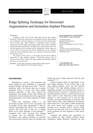
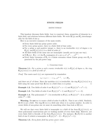
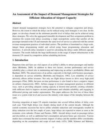
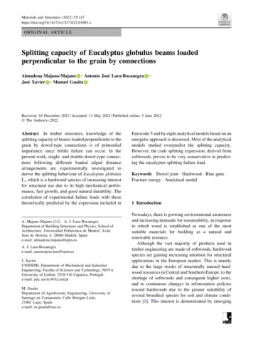
147 Page 4 of 17Regarding the fracture properties of E. globulus, theevaluation of Mode I fracture energy is detailed in [43]and [44] using Double Cantilever Beam (DCB)specimens (Fig. 1a). A mean value of the criticalstrain energy release rate GIc 0.77 N/mm wasderived from the resistance curves (R-curves) following the compliance-based beam method (CBBM) as adata reduction scheme. This method was also appliedto determine the critical strain energy release rate inMode II loading from end-notched flexure (ENF) tests(Fig. 1b), resulting in a mean value of GIIc 1.54 N/mm [45].Table 2 summarises the mean values of theseproperties that will be considered in the differentanalytical models to study the splitting behaviour of E.globulus.2.2 Splitting tests32 splitting tests were conducted on planed E. globulusspecimens of 29 9 116 mm2 cross-section, 580 mmlength and 500 mm span. This and similar crosssections are readily available in this species.Two series of three-point bending tests were carriedout on single and double dowel connections withdifferent arrangements of loaded edged distances (he):(a)A single steel dowel of d 16 mm diameter andof S355 quality placed in the middle of thebeam. Three he were evaluated: 2d ,3d and 4d (32 mm, 48 mm, and 64 mm)(Fig. 2a). The relative height of the connectionis sometimes simplified by the parameter a( he/h). The configurations mentioned correspond to a values of 0.27, 0.41 and 0.55,respectively (test data reported in the literaturehave shown that a values up to 0.7 may fail byFig. 1 a Double cantilever beam test; b end-notched flexure testMaterials and Structures (2022) 55:147(b)splitting [37], with the splitting check restrictedto a B 0.7 in the former German standard [28]).It should be noted that he 4d corresponds tothe minimum loaded edge distance set out inEurocode 5 [30], but there is always thepossibility of execution errors when drillingholes on site, which are particularly relevant instructures with small depth elements, such as theones studied here. Between seven and ninebeams were tested for each configuration.Two steel dowels in a row of d 16 mm indiameter and quality S355, spaced 3d (48 mm)apart between their centres and placed athe 4d (64 mm) as shown schematically inFig. 2b. Eight beams were tested with thislayout.The diameter of the steel dowels was chosen to besufficiently thick to prevent yielding. These wereloaded by two outer plates made of Eucalyptusglobulus with characteristics similar to those of thebeams (note that no embedment damage occurred inthe plates). A load cell of 50 kN maximum capacitywas used. The tests were carried out at a constantcross-head displacement rate of the test device,adjusted to reach failure in approximately 5 min(2 mm/min, 1 mm/min and 0.5 mm/min for he 4d,he 3d and he 2d layouts, respectively, in thesingle-dowel tests; 0.7 mm/min velocity in the double-dowel tests). During the loading process, theapplied load (P) and the displacement (d) wererecorded. For the latter, two Linear Variable Differential Transformer (LVDT) displacement sensors,Solartron AX/10/S, with 10 mm measurementrange and 20 mV/V/mm sensitivity, were used: onewas located on the middle bottom side of the specimenand the other at the top of the steel dowel.
Materials and Structures (2022) 55:147Page 5 of 17147Table 2 Number of specimens (n), mean value, and coefficient of variation (CoV) of the different properties of E. globulusGLR (N/mm2)n10Mean1926CoV (%)24ft,90 (N/mm2)GIc (N/mm)GIIc (N/mm)3613107.5160.77231.5428Fig. 2 Connection geometries: a Single-dowel; b double-dowel3 Analytical models studiedThe considered analytical fracture mechanics modelsfor the analysis of the splitting capacity of beamsloaded perpendicular to grain by connections areshown in Table 3. A comprehensive review of most ofthese approaches can be found in [35, 41]. Therefore,in this work, only a summary of these models will bepresented. Most of the models are related and appearas special cases of a general one, where the failure loadis determined for a linear elastic body loaded with asingle force, based on the energy balance approach[47] and the fracture mechanics compliance methodaccording to Eq. (1):sffiffiffiffiffiffiffiffiffi2GfPu ¼ dCðAÞð1ÞdAbeing A and C the crack area and the modelcompliance, respectively.The different analytical models in Table 3 arederived using Eq. (1) making certain assumptions onhow to calculate the compliance C(A), which leads to agood agreement with the experimental data. Theexternal load is assumed to act at a single point in themiddle of the beam. The parameters considered by themodels are both material and geometrical. The material properties are the fracture energy, Gf (GIc of theMode I loading in most models); the shear modulus ofelasticity, G; the longitudinal modulus of elasticity, E;and the tensile strength perpendicular to the grain, ft.The main geometric parameters are the width of thebeam, b; the height of the beam, h; the distance fromthe connector to the loaded edge of the beam, he; therelative height of the connection, a ( he/h); the shearcorrection factor, bs, which takes the value of 6/5 for arectangular cross-section according to ordinary beamtheory; the number of rows of dowels parallel to grain,n; and the connection width, ar.Jensen [34] formulated one of the most generalmodels as an extended version of the original Van derPut and Leijten model [33], which will be discussedbelow, but without any simplifying assumptions, suchas neglecting the normal forces in the cracked parts ofthe beam. The model was derived considering acracked beam structure modelled by beam elements,all rigidly connected. The failure load is given byEq. (2).Another model which appears as a special case ofthe model expressed by Eq. (2) was later proposed byJensen et al. [35], derived this time from consideringthat the part of the beam below the crack behaves like abeam with fixed ends, of length the crack and depth he.The expression is shown in Eq. (3), which would alsobe arrived at by assuming h ? ? for a finite value ofhe (i.e. a ? 0) in Eq. (2), that is, all beams except thebeam with depth he are assumed to be infinitely stiff.When only shear deformations are considered andthus bending deformations are neglected (i.e., finite G,
147 Page 6 of 17Materials and Structures (2022) 55:147Table 3 Analytical models for the analysis of the splitting capacity of beams loaded perpendicular to grain by connectionsReferenceAnalytical ModelJensen (2005a) [34]Pu ¼ 2bJensen et al. (2015) [35]Pu ¼ �ffiffiffiffiffiffi2GGf heEquation (2)23GEðhae Þ ð1 a3 Þþbs ð1 ��ffiEquation (3)2GGf he23GEðhae Þ þbsqffiffiffiffiffiffiffiffiffiffiffi2GGf hebs ; bs ¼ �ffiffiffiPu ¼ 2bC1 1 hehe ; C1 ¼ 53 �ffiffiffiffiffihePu ¼ 2bk 1 a3 fw fr ; k ¼ 53 GGfEquation (5)Jensen (2005b) [38]Pu ¼ cPu;LEFMEquation (7)Jensen et al. (2015) [35]Pu ¼ cPu;LEFMEquation (8)Franke and Quenneville (2011) [39]Pu ¼ GLarsen and Gustafsson (2001) [36]Van der Put and Leijten (2000) [33]Ballerini (2004) [37]Pu ¼ ��ffiPu;LEFM ¼ 2bC1 he ; C1 ¼ 53 GGf �ffiffiffiffi21þ1; 1 ¼ Cft1 10 GE h1ec ¼ �ffiffiffiffiPu;LEFM ¼ 2bC1 1 hehe ; C1 ¼ 53 �ffiffiffiffiffi21þ1C1c ¼ 1þ1 ; 1 ¼ ft 10 GE h1eb 103GI;normII;normGIc þ GIIc krEquation (4)Equation (6)Equation (9) 1 0:25GI;norm ¼ eðh ð200 10he h ar ÞÞGII;norm ¼ 0:05 þ 0:12 hhe þ 1 10 3 ar(1 for n ¼ 1kr ¼0:6 for n [ 10:1 þ ðarctanðnÞÞE ? ?), the ratio G/E ? 0 and Eq. (3) is reduced tothe form expressed in Eq. (4). This expression issimilar to the solution proposed by Larsen andGustafsson [36] when bs 1 is assumed.A renowned simple analytical model that forms thebasis for the design in Eurocode 5 [30] is the oneproposed by Van der Put and Leijten [33] expressed inEq. (5). Due to the similarity in behaviour, the sameprinciple was followed as in the mechanical fracturemodel for the splitting of beams with notches previously derived by Van der Put [32]. The expression isobtained by analysing the cracked state of a beamunder an energy balance approach when the joint loadis perpendicular to the grain near the loaded edge,using experimental results from the literature ascalibration. Although today it is still the model basisof the normative expression, it has been subject tosubsequent alterations and adjustments by differentresearchers. In this sense, the resulting expressioncould again be seen as a special case of the generalmodel presented in Eq. (2) neglecting bending deformations and taking into account only shear deformations (that is, G/E ? 0) and bs 6/5 for rectangularcross-section. In the cases where he/h ? 0, the van derPut model would lead back to the solution presented inEq. (4).Ballerini [37] proposed a semiempirical modelgiven by Eq. (6), in an effort to better fit theexperimental data than using the van der Put andLeijten formula for single-dowel connections. Thework also provides an approach for multiple-dowelconnections and is further elaborated with parametricnumerical analysis by Ballerini and Rizzi [48]. Itconsiders the influence of the connection width anddepth using correction functions applied to the singledowel formula. In particular, the correction factor toaccount for the influence of the width of the connection is fw 1 ? 0.75(lr ? l1/h) B 2.2, where lr is thespacing between the dowels and l1 is the distancebetween the dowel clusters (this correction function
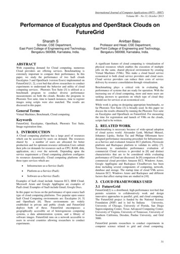
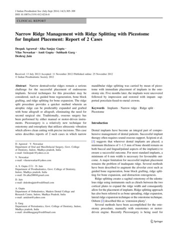
Materials and Structures (2022) 55:147will be applied in the case of double dowel connections studied in the present work).Jensen postulated other analytical models based onthe beam-on-elastic foundation (BEF) [38]. In thiscase, the crack plane is modelled by springs to whichthe fracture properties are assigned. After cracking,the beam below the fictitious fracture layer is considered as a beam resting on elastic Wrinkler springsconnected to the upper part, which is assumed to beinfinitely rigid (foundation). For a single load actingfar from the end of the beam and small crack lengths,the failure load is given by Eq. (7), where c is theeffectiveness factor. Unlike the models mentionedabove, this expression includes the tensile strength ft inthe parameter f, and the splitting failure load is notproportional to the square root of the fracture energy.Therefore, solutions cannot be encompassed withineither linear elastic fracture mechanics (LEFM) ornonlinear fracture mechanics (NLEFM). They belongto quasi-nonlinear fracture mechanics, and LEFMsolutions are considered special cases.Assuming E ? ? or ft ? ? in the analyticalapproach of Eq. (7), the solution Pu Pu,LEFM wouldbe obtained. The same solution could also be derivedfrom Eq. (4) for bs 6/5, and from Eq. (5) when he/h ? 0. Therefore, it seems feasible to use, as Pu,LEFMin Eq. (7) the linear elastic fracture mechanics solutiongiven by Eq. (5). In this way, the analytical modelexpressed by Eq. (8) is obtained. When he/h ? 0,Eq. (8) leads to Eq. (7), and when E ? ? or ft ? ?it becomes Eq. (5). Equation (8) is therefore a semiempirical generalization of Eq. (7) that considers theeffect of the total beam height.Franke and Quenneville [39] presented a completeapproach based on a quadratic failure criterion inwhich fracture modes I and II for tension and shear areconsidered using the corresponding fracture energiesGI and GII. It should be noted that virtually all fracturesare, in fact, mixed-mode fractures, but the mixedmode ratio is not considered by the aforementionedcompliance method. As the GI of wood is usuallymuch lower than the GII, the GI is usually consideredin most splitting models as a conservative assumptionand reasonably accurate approximation, but themixed-mode fracture energy would represent the mostrealistic situation. The Franke and Quenneville formula also takes into account the width of theconnection and the number of rows of dowels, andthey found that the geometry of the connectionPage 7 of 17147influenced the ratio between fracture modes I and II.The design proposal is given by Eq. (9) as a result ofan experimental and numerical investigation by finiteelement analysis of more than 100 different connection arrangements.All of the above models are similarly acceptable from a modelling perspective. From a practicaldesign point of view, simple and robust models seemto be more attractive.4 Results and discussion4.1 Experimental failure loadsThe failure behaviour of the series of specimens withone and two dowels in a row and different distancesfrom the loaded edges subjected to splitting tests isherein presented.In the single-connection tests, a main crack couldalways be observed growing from both sides of thedowel (Fig. 3a). This crack developed at slightlydifferent positions, starting at the mid-down part of thedowel contact. The smaller the loaded edge distance,the faster the crack developed with respect to themaximum load capacity. In these test groups, the cracknever reached the ends of the beam.Some of the specimens with the largest loaded edgedistance (4d) showed embedding deformations underthe dowels, but no bending of the dowels, as well assome cracks with small lengths beside the dowel(Fig. 3b). The beams with 2d and 3d loaded edgedistances did not exhibit any significant embedmentunder the dowels. In any case, the brittle failure wasalways characterised by one main crack.Regarding the double-dowel tests, a similar crackgrowth process was observed as for the single-dowelbatches in the sense that just one main crack developedon both sides of the beams. However, in all tests, thecrack reached the beam ends, producing a completeseparation of the specimen into two parts with a verybrittle and sudden failure (Fig. 4a).No embedment deformations were observed underthe two dowels (Fig. 4b, unlike in the case of a singledowel for the same loaded edge distance (4d), as thebearing area increases with the two closely spaceddowels.These failure modes are well represented by thecorresponding load versus displacement curves
147 Page 8 of 17Materials and Structures (2022) 55:147Fig. 3 a Representative failure behaviour of single-dowel test series; b detail of the local failure around the dowel for the three loadededge distancesFig. 4 a Representative failure behaviour of the double-dowel test series; b detail of local failure around the dowelsmeasured at the top of the dowels. The results of thesingle-dowel splitting tests are shown in Fig. 5a,which reveal the different failure behaviour of theinvestigated connection arrangements.As can be seen, the load–displacement curvesobtained from the beams with the greatest edgedistance (4d) show a ductile behaviour characterisedby embedment stresses and yielding followed byhardening. The connection is still able to force asplitting failure after considerable slip, althoughsplitting is not the primary failure mode. On theFig. 5 Load–displacement curves. a Single-dowel splitting tests with 2d, 3d and 4d loaded edge distances; b double-dowel splittingtests with 4d loaded edge distance
Materials and Structures (2022) 55:147Page 9 of 17contrary, a brittle failure response is displayed forlower edge distances (3d and 2d).The load–displacement curves of the double-dowelsplitting tests with a 4d loaded edge distance areshown in Fig. 5b. In this case, a clear brittle behaviouris observed in all specimens for the a-value studied.Failure loads (Pu) achieved in all splitting tests forthe beams with single- and double-dowel arrangements as well as the mean value, the standarddeviation (SD) and the coefficient of variation (CoV)are compiled in Table 4.As can be seen from the results of the single-dowelbeams, the load-carrying capacity increases withincreasing loaded edge distance.The failure loads reached by the beams with twodowels are not necessarily twice as high as thoseachieved by the beams with a single dowel arrangement at the same loaded edge distance 4d (a 0.55),but the mean value is only slightly higher (21%higher). These results are in agreement with thoseobtained by Quenneville and Mohammad [49], whotested different connection arrangements on sprucepine glulam beams, including series of one and twofasteners spaced horizontally 5d apart, with a 0.6.The mean maximum loads in the case of doublefasteners were found to be 23% higher compared to thesingle connection. Previous experimental investigations by Reshke [50] for the same material and jointgeometry as specified for [49], also resulted in a smalldifference of approximately 14% higher failure loadTable 4 Failure loads fromthe single- and doubledowel splitting tests147for specimens with two dowels compared to those withone dowel.The fact that two closely spaced dowels givebasically the same splitting failure load as a singledowel was also stated by Kasim and Quenneville [51]using the concept of cluster (group) of fasteners. Intheir research, the capacity of two rows of boltsseparated 4d in the direction parallel to the grainturned out to be lower or statistically not different fromthat of one row of bolts on spruce glulam beams witha 0.44 and a 0.70. As the spacing of the rowsincreased, so did the splitting capacity of the connection. The two-row joint behaved almost as twoseparate single rows if the spacing between the rowswas C 2he (75% of twice the capacity of the one-rowconnection was obtained). The angle of load distribution from a bolt towards the loaded edge was estimatedto be 45 . In this regard, the former German code [28]limited to less than 0.5h the distance between groupsof fasteners in the direction parallel to the grain to beconsidered as one group. For distances C 2 h betweenthem, they are treated as separate groups. For distancesbetween 0.5h and 2h, the groups are considered as onegroup, but a reduction factor is applied. Quennevilleand Mohammad [49] stated that a connection can beassumed to be one cluster if the distance parallel to thegrain between the rows of bolts does not exceed he.The assumed angle of load distribution was 638 in thiscase.1 dowel2 dowelshe 2d 32 mmhe 3d 48 mmhe 4d 64 mmhe 4d 64 mmnamePu (kN)namePu (kN)namePu (kN)nameP
hardwood products, mainly glued laminated products [e.g., 2-4]. In this regard, Eucalyptus globulus Labill (also known as southern blue gum) stands out as a high-