Transcription
Shop Fabricated StationaryAboveground Storage TanksFor Flammable, Combustible LiquidsINSTALLATION INSTRUCTIONSJuly 202211.11.21.31.4TANK SITE EVALUATION AND PREPARATIONPRIOR TO INSTALLATIONThe foundation for the tank must be designed tosupport the weight of the tank plus 100% of theweight of the tank’s contents when full. The designshall also take into account the type of support thatis being used and the point load associated with thatsupport. The foundation may be constructed usingconcrete, asphalt, gravel, or other stable materialand must include provisions in its design to preventtank movement. The foundation design shouldinclude any provisions necessary for seismicconsiderations, applicable local building ions for exposure to winds. Thefoundation design must also include provision fordraining surface water away from the tank.22.1TANK HANDLINGDo not handle or install tank without havingknowledge and experience in procedures in- volvedwith proper and safe installation of an abovegroundtank used for storage of stable, flammable, andcombustible liquids. To avoid tank damage, useskilled, professional installers.2.2Equipment for handling the tank shall be of adequatesize to lift and position the tank. DO NOT DROP ORDRAG THE TANK.2.3Tanks shall be carefully handled. Use cables or chainsof adequate length (with spreader bars, if necessary)and size. Attach to the tank using the lifting lugsprovided. Care should be taken that the anglebetween the two cables, at the lift point, shall be nogreater than 60 degrees.For tank installations without cathodic corrosionprotection, the tank should be grounded inaccordance with applicable electrical and fire codestandards.2.4DO NOT HANDLE OR MOVE THE TANK UNLESS IT ISEMPTY OF LIQUID AND FREE OF VAPORS.2.5This is a stationary tank. Do not use this tank fortransport of any product.3TESTING OF TANK INTEGRITY AT THE TIME OFINSTALLATION, AFTER REPAIRS, OR TO CONFIRMTANK INTEGRITY AS PART OF TANK MAINTENANCEGENERAL REQUIREMENTSWhere the tank body is in contact with the earth orfoundation, it should be protected from externalcorrosion. For external corrosion protection usingcathodic corrosion protection, consult applicablestandards (e.g., NACE/AMPP) to provide the tankwith appropriate protection from lightning withoutinterfering with the corrosion protection. Steeltanks in contact with the earth should not usecopper grounding. Refer to STI R893-89,“Recommended Practice for External CorrosionProtection of Shop Fabricated Aboveground StorageTank Floors.”Tanks located in areas subject to flooding must beprotected against flotation. Aboveground tanksshould not be located above underground utilitiesor directly beneath overhead power lines. The tankshall be protected from vandalism and accidentaldamage in accordance with all applicable codes.3.13.1.1An on-site integrity test of the tank may be requiredby local authorities after the tank is placed to ensureno damage has occurred in shipping and handling,after a tank repair or as part of tank maintenance toconfirm the integrity of the tank system. A pressuretest or vacuum test may be used to evaluateintegrity. However, the Authority Having Jurisdiction(AHJ) or a responsible party overseeing the workshould establish the appropriate method. All testingshall be performed as described in paragraph 3.2below.
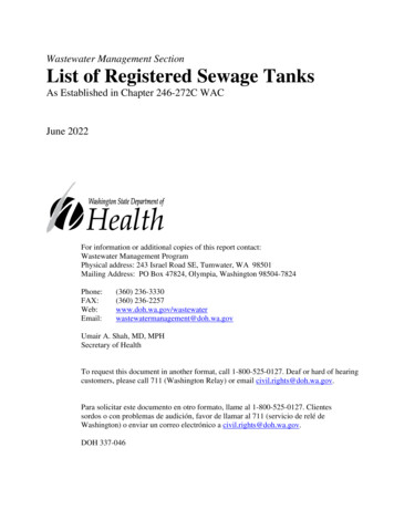
3.1.2In-shop testing during tank manufacture will beperformed at different pressures which are specifiedby the tank construction standard.If the manufacturer has shipped the double walltank with a vacuum on the space between thewalls, this may serve as the onsite integrity test withAHJ approval if vacuum is held until the tank isplaced. Read and record the vacuum pressure ofthe tank at the time of delivery and at the time oftank placement. The vacuum reading at the time ofshipment should be provided by the tankmanufacturer. If the vacuum gauge reading hasdropped more than 2 inches Hg (40.5 6.77 kPa)from the level at which it was shipped, contact thetank manufacturer. Remember that vacuum candecrease if the tank environment is warmer thanwhen the tank was originally put under vacuum.3.2AIR PRESSURE TEST PROCEDURE FOR TANKS3.2.1Manways must be secured with bolts and/or Cclamps of appropriate size and strength to hold thevent cover in the sealed position to maintain thetank pressures required. If the manway is to beused as the emergency vent (i.e., long boltmanway) the manway must be returned to the longbolt configuration at the completion of the test.Tanks listed per UL will not be shipped with longbolt manways as E-vents after March 2021. If tankis equipped with standard emergency vents,remove emergency vents and cap openings to holdtank pressure as required.NOTE: Use only calibrated air pressure gauges witha 0-15 psig (0-103 kPa) dial span. The relief valvemust have a flow rate at the set pressure that isgreater than the flow rate of the air supply line. Theregulated air supply test pressure used for this testshould be as follows:CAUTION: Do not leave a pressurized tankunattended while the air supply line is connected, orany tank compartment is at an elevated pressure. Donot stand in front of tank heads or fittings whenpressurizing tank.Pressurizing of large tanks may result in the slightdeformation or bulging of the tops and bottom ofvertical tanks, bulging of the sides of rectangulartanks, and bulging of the heads and ends ofcylindrical tanks. Should visible bulging occur, ordeformation appear severe, immediately relieve thepressure. Aboveground vertical tanks may have a"weak shell to roof" seam. Do not air pressure test atank with a “weak shell to roof” seam. Rather, fillthese tanks with water and check for leaks. Alsoremember that as temperature increases the tankpressure may increase. Regularly monitor the tankpressure during the test and release tank pressure ifsite conditions cause pressure to rise above theallowable limits set in section 3.2.1.3.3SINGLE-WALL TANK PRESSURIZING PROCEDURE3.3.1Install test piping as shown in Figure 3.3.2.Temporarily plug, cap, or seal off remaining tankopenings to hold pressure.3.3.2Close valves A and B.a. HORIZONTAL CYLINDRICAL (AND DIKEDTANKS, IF APPLICABLE) TANKS - Not less than 3psig (20.7 kPa) nor more than 5 psig (34.5 kPa).Set the pressure relief valve in the air supply lineat 5 psig (34 kPa).b. VERTICAL TANKS - Not to be less than 1 ½ psig(10.4 kPa) nor more than 2 ½ psig (17 kPa) orthat gauge pressure above 1 ½ psig (10.4 kPa)which first causes visible deformation of thetank. Set the pressure relief valve in the airsupply line at 2 ½ psig (17 kPa).c. RECTANGULAR TANKS - Not more than 1 ½ psig(10.4 kPa). Tank pressurization should stop ifthe tank shell starts to deform. Set the pressurerelief valve in the air supply line at 1 ½ psig (10.4kPa). This 1 ½ psig (10.4 kPa) pressure is to beused for testing tanks in the field ONLY.FIGURE 3.3.2SINGLE-WALL TANK3.3.3Connect regulated test air supply line to test pipingas shown in Figure 3.3.2.3.3.4WARNING: A relief valve should be installed in atank opening and set at the maximum test pressureto prevent causing tank failure by overpressurization.
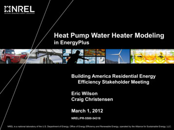
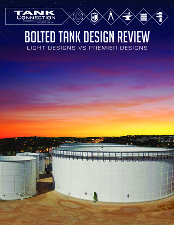
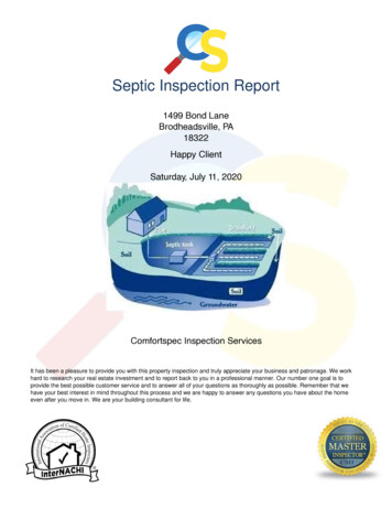
3.3.5Slowly open valve A to pressurize the tank. Pressuregauge should indicate test air pressure given inparagraph 3.2.1 above. Close valve A. Disconnectregulated test air supply line from test piping.If the tank is a multiple compartment tank test eachcompartment separately if the tank compartmentsshare a common bulkhead. If the tank does notshare common bulkhead with the neighboringcompartment, then the individual tankcompartments can be tested simultaneously. Forcompartmented tanks, each compartment must betested separately if single bulkheads are used. Ifcompartments use double bulkhead construction,the individual compartments can be testedsimultaneously. Proceed to paragraph 4 “Detectionof Leaks” below.FIGURE 3.3.8DOUBLE-WALL TANK3.4DOUBLE-WALL TANK PRESSURIZING3.4.1The following air pressure testing does not apply todouble-wall tanks equipped with interstitialvacuum monitoring systems. In lieu of the airpressure test, the tank may be shipped from thefactory with a vacuum in the tank interstice. If thevacuum pressure, gauge reading has deviated morethan 2 inches Hg (40.5kPa) from the shippingpressure contact the tank manufacturer.3.4.2The following air pressure testing applies only tosingle compartment double wall tanks. Follow theprocedure described in section 3.5 to test multicompartment double wall tanks. Read and recordthe vacuum pressure.3.4.3Install test piping as shown in Figure 3.3.8.Temporarily plug, cap, or seal off remaining tankopenings to hold pressure.3.4.4Connect regulated test air supply line to test pipingas shown in Figure 3.3.8.3.4.5Close valves A and B. Open valve C.3.4.6Slowly open valve A to pressurize the primary tank.Pressure gauge 1 should indicate test air pressuregiven in paragraph 3.2.1.3.4.7Close valve A. Disconnect regulated test air supplyline from test piping.3.4.8Monitor test pressure in primary tank for 1 hourminimum. A steady drop in pressure reading forgauge 1 indicates there may be a leak in the primarytank. Check the fittings, and gauge, then retest. Ifthe problem persists, contact the tankmanufacturer.3.4.9If no leaks are found, close valve C and slowly openvalve B to pressurize the interstitial space betweenthe double walls of the tank. Pressure gauge 1 willindicate a slight drop in test pressure when valve Bis opened but should hold steady at the lowerpressure. If test pressure drops below minimumrequirements found in 3.2.1, close valve B,reconnect air supply line and slowly open valve A toincrease pressure in primary tank. When therequired pressure is indicated on gauge 1 close valveA, disconnect test air supply line. Open valve B toequalize pressure in the primary tank and theinterstitial space. Gauge 1 and gauge 2 should havethe same pressure reading.WARNING: Do not apply air pressure to theinterstitial space between the walls of a double walltank without air pressure in the primary tank.Several re-pressurization cycles may be needed topressurize the interstitial space of a protectedand/or insulated tank because the insulatingmaterial will absorb some of the air duringpressurization. A tank that is 20,000 gallons or lessmay require up to four re- pressurization cycles, anda tank large than 20,000 gallons may require up tosix re- pressurization cycles. Do not apply airpressure to the interstitial space that is higher thanthe air pressure in the primary tank. Damage to thetank may result.
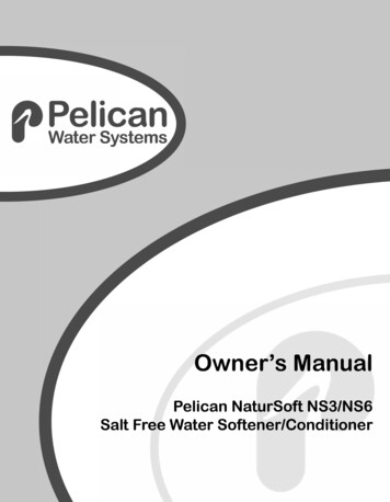
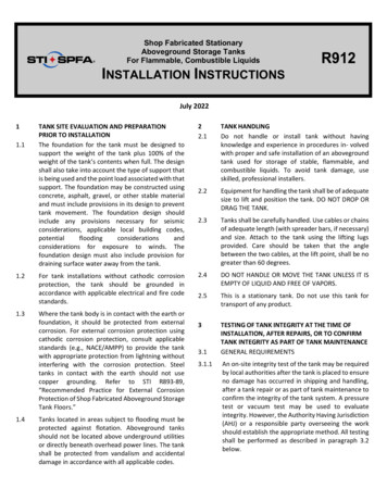
3.4.10 Upon stabilization of pressure in the interstitialspace close valve B and disconnect the air line. Holdtest pressure in interstitial space for 1 hourminimum. A steady drop in pressure gauge 2indicates there may be a leak in the interstitialspace. The tank test pressure should not vary morethan 5% during the test. Check the test fittings, thegauges, tank fittings and then retest if varianceexceeds 5%. Be especially careful to check theemergency vent cap or plug for leaks. If theproblem persists, contact the tank manufacturer.Do not leave the tank unattended if any part of thetank is under pressure.3.5.4Once the individual compartments have been testedand have passed, the tank should be configured asshown in Figure 3.5.8 to allow the tankcompartments to be pressurized simultaneously,and then to allow the pressure from the primarytank to be transferred to the secondary tank.3.5.5Close valves A and B. Open valve C. Slowly openvalve A to pressurize the primary tankssimultaneously. Pressure gauge 1 should indicatetest air pressure given in paragraph 3.2.1.3.5.6Close valve A. Disconnect regulated test air supplyline from test piping.3.4.11 Proceed to paragraph 4 “Detection of Leaks” tocomplete testing. In lieu of the air pressure testdescribed in this section, a vacuum may be appliedto the interstice of a double-wall tank or to theinterstice of a double-bottom tank as described inparagraph 3.6.3.5DOUBLE WALL MULTI COMPARTMANT TANKPRESSURIZING3.5.1Multi compartment tanks can be pressure testedhowever when testing secondary containment typemulti compartment tanks steps must be taken toprevent pressurizing the secondary tank when theprimary tanks are not also under a pressure at leastequal to the test pressure of the secondary tank. Ifthe secondary tank pressure exceeds the primarytank pressure(s) the primary tank(s) may bedamaged.3.5.23.5.3The first step is to pressure test the individual tankcompartments to confirm their integrity. Multicompartment tanks which have commonbulkheads must have each compartment testedindividually. Multi compartment tanks that haveindividual tank bulkheads separated from theadjoining tank bulkhead can have the tankcompartments tested simultaneously. The type ofcompartment construction can be established viathe tank drawing or by contacting the tankmanufacturer. If the tank construction cannot beestablished test each compartment individually asif the tank compartments share bulkheads.WARNING: A relief valve should be installed in atank opening and set at the maximum test pressureto prevent causing tank failure by overpressurization.FIGURE 3.3.8DOUBLE-WALL MULTI COMPARTMENT TANK3.5.7Monitor test pressure in primary tanks to confirmtest assembly integrity. A steady drop in pressurereading for gauge 1 indicates there may be a leak inone of the primary tanks or test fittings. If leak issuspected, check the fittings, and gauge, then retest.If the problem persists, reconfigure the tanks to testeach compartment separately. If the leak cannot beidentified, contact the tank manufacturer.3.5.8If no leaks are found, close valve C and slowly openvalve B to pressurize the interstitial space betweenthe double walls of the tank compartments.Pressure gauge 1 will indicate a slight drop in testpressure when valve B is opened but should holdsteady at the lower pressure. If test pressure dropsbelow minimum requirements, close valve B,reconnect air supply line and slowly open valve A toincrease pressure in primary tank. When therequired pressure is indicated on gauge 1 close valveA, disconnect test air supply line. Open valve B toequalize pressure between the primary tanks andthe interstitial space. Gauge 1 and gauge 2 shouldhave the same pressure reading.
3.5.9Several re-pressurization cycles may be needed topressurize the interstitial space of a protected tankbecause the insulating material will absorb some ofthe air during pressurization. A tank that is 20,000gallons or less may require up to four repressurization cycles, and a tank large than 20,000gallons may require up to six re- pressurizationcycles. Re-pressurizations are done by transferringair from the primary tanks to the secondary tank.Air pressure may need to be added to the primarytanks to maintain test pressure. Do not apply airpressure directly to the interstitial space. Damageto the tank may result. Only apply air pressure tothe interstitial space of a double wall tank when theair pressure in the primary tank is equal to the testpressure.3.5.10 Once the pressures have stabilized close valve B.Upon stabilization of pressure in the interstitialspace hold test pressure in interstitial space for 1hour minimum. A steady drop in pressure gauge 2indicates there may be a leak in the interstitialspace. The tank pressure or the pressure in theinterstitial space should not vary more than 5%during the test. If leak is suspected, check the testfittings, the gauges, the tank fittings and thenretest. Be especially careful to check the emergencyvent cap or plug for leaks. If the pressure in theinterstitial space should exceed the pressure in theprimary tanks, valve C should be opened todischarge the pressure for the interstitial space andthe source of the leak is found. If the problempersists, contact the tank manufacturer.3.5.11 Proceed to paragraph 4 “Detection of Leaks” tocomplete testing. In lieu of the air pressure testdescribed in this section, a vacuum may be appliedto the interstice of a double-wall tank or to theinterstice of a double-bottom tank as described inparagraph 3.6.3.6VACCUM TEST FOR DOUBLE WALL AND DOUBLEBOTTOM TANKS3.6.1NOTE: This test procedure may be difficult toconduct for large (greater than 20,000 gallons)tanks because of the greater volume of space to beevacuated and difficulty in sealing the tankopenings. DO NOT APPLY A VACUUM TO THEPRIMARY TANK OF A DOUBLE-WALL TANK OR TOA SINGLE-WALL TANK. A vacuum of 6 inches Hg(20.3 kPa) is to be applied to the interstice only. Thevacuum shall be allowed to stabilize for 10 minutesand, if the vacuum is lost due to tank shifting or theeffects of temperature, the test vacuum can be re-established. Once the test pressure is stabilized thevacuum should be held without a loss for one houron tanks less than 20,000 gallons and for 2 hours fortanks greater than or equal to 20,000 gallons. If thisvacuum cannot be held for the specified timeinterval, then perform the air test proceduredescribed in paragraph 3.4 or 3.5 as appropriate,and the leak check described in paragraph 4.3.6.2Caution must be taken in applying a vacuum to theinterstice of a tank and the testing must be stoppedif any deformation appears on the tank.3.6.3Performing a vacuum test on an insulated tank canbe difficult due to the porosity of the tank insulation.The vacuum will need to be applied in stages toallow the insulation to yield trapped air. Vacuumshould be checked 15 minutes after it is applied tocheck for stabilization. Vacuum can be re-applied ifthe level has dropped from test value. This processcan be repeated up to four times for a tank less than20,000 gallons in capacity and six time for a tankgreater than 20,000 gallons. After the stabilizationperiod is complete the interstitial vacuum can be setat 6” hg, the tank should hold the vacuum for onehour if less than 20,000 gallons capacity and twohours if the tank is greater than 20,000 gallonscapacity. The vacuum should not vary more than 5%during the test (0.3” hg) for the duration of the test.If this vacuum cannot be held for the specified timeinterval, then perform the air test proceduredescribed in paragraph 3.4 or 3.5 as appropriate,and the leak check described in paragraph 4.44.1DETECTION OF LEAKSImmediately apply leak test solution to tank exteriorsurfaces, welds, fittings, etc. Check for leaks. Noleaks are permitted. If leaks are found, notify thetank manufacturer. If no leaks are found, testing ofthe tank is complete.
4.2For single-wall tank, open valve B, then slowly openvalve A to release test air pressure. For double-walltank, open valve C, then slowly open valve B torelease test air pressure.4.3WARNING: A relief valve should be installed in theair supply line and set below the maximum pressurelisted in 3.2.1.55.1TANK PIPING AND ACCESSORIESInstall all permanent piping and fittings usingcompatible, non-hardening thread sealant material.All openings should be inspected and cleaned priorto attaching components to the tank.5.2All unused tank openings must be properly sealedwith metal pipe plugs or caps and tested to be liquidand vapor tight prior to putting the tank into service.6.3Proper site preparation and maintenance are vital toensure drainage of surface water. Should groundconditions change or settlement occur, take theappropriate steps to maintain proper drainage andprevent standing water near or under the tank area.6.3.1For diked tanks, remove any product spillsimmediately. Be sure to dispose of hazardousmaterial properly.6.3.2For diked tanks fitted with a drain, drain off wateronly. Drain openings are required to be maintainedliquid tight.6.4The primary tank should be inspected monthly forthe presence of water at the lowest possible pointsinside the primary tank. Remove any water found.Water and sediment in fuel can cause plugging offilters. Also, bacterial growth in this media can causefilters to plug, diminish fuel quality and causecorrosion of tanks and lines. For procedures on howto check for the presence of water and removal ofwater, refer to STI RP111, Storage TankMaintenance. For copies of the RP and moreinformation, please go to www.steeltank.com.6.5Tank relocation requirements – Abovegroundstorage tanks are often relocated. The followinginstructions are to be followed when this occurs. Allsteps are to be documented and the documentationis to be kept for the life of the tank.6.5.1The hazards associated with the cleaning, entry,inspection, testing, maintenance, or other aspects ofASTs are significant. Safety considerations andcontrols should be established prior to undertakingphysical activities associated with ASTs. Cleaning oftanks must be per state and local jurisdictionrequirements.6.5.2Refer to STI Standard SP001, “Standard for theInspection of Aboveground Storage Tanks” forrequirements concerning tank inspections. ThisSP001 Standard details requirements for inspectionsbased on the tank installation and age. A tank mustundergo the appropriate inspection prior torelocation.DO NOT WELD ON THE TANK, MODIFY ORPENETRATE THE TANK STRUCTURE IN ANY WAYWITHOUT THE EXPRESS WRITTEN PERMISSION OFTHE TANK MANUFACTURER.5.3All tank accessories shall be installed as required perlocal codes and manufacturer recommendations.Anti-siphon devices, overfill shut-offs and alarms,vents, gauges, emergency vents, etc. are commonrequirements for tank systems storing anddispensing motor fuels.66.1MAINTENANCEThe tank operator should perform periodic walkaround inspections to identify and repair areas ofdamage to the tank or the coating. Check for properdrainage around the tank area.6.2It is imperative that the tank exterior be inspectedperiodically to ensure that the integrity of thecoating is maintained. The frequency of periodicrepainting will be based upon environmental factorsin the geographic area where the tank is located.Special consideration should be given to theselection of the paint, surface preparation andcoating application. The coating selected should besuitable for use with the current coating, or theexisting coating should be removed. The coatingselected should be of industrial quality. Care mustbe taken to ensure that tank certification label andserial number label are preserved as these areunique to the tank.The tank must be subjected to a pressure (orvacuum) test as detailed paragraph 3.2 aboveexcept an inert gas, such as nitrogen, should be usedfor tanks that have previously held fuel.DISCLAIMERThese instructions are intended only as an aid to tank installers who are knowledgeable and experienced in aboveground tank installation. Complianceherewith does not necessarily meet the requirements of applicable federal, state and local laws, regulations and ordinances concerning tank installation.STI makes no warranties, express or implied, including but not limited to, any implied warranties of merchantability or fitness for a particular purpose, as aresult of these installation instructions. Contact STI for the latest version of these Installation Instructions or visit the STI website at www.steeltank.com.
TANKS, IF APPLICABLE) TANKS - Not less than 3 psig (20.7 kPa) nor more than 5 psig (34.5kPa). Set the pressure relief valve in the air supply line at 5 psig (34 kPa). b. VERTICAL TANKS - Not to be less than 1 ½ psig (10.4 kPa) nor more than 2 ½ psig (17 kPa) or that gauge pressure above 1 ½ psig (10.4 kPa)