Transcription
Project Number: IQP-SJB-B20102011Automobile Safety TechnologyAn Interactive Qualifying ProjectSubmitted by:Scott J. Cloutier and David H. LinkeAdvised by:Professor Stephen J. BitarPage i15th, 2011October
AbstractThe purpose of this project was to evaluate the educational level of the WPI communityon automobile safety devices and develop an interactive medium through which visitors canestablish a better understanding of the technology. An interactive video presentation andmuseum exhibit were constructed together to educate the community on the criteria ofhistory, purpose, and functionality for several major automotive technologies. The presentationcomponent incorporated pictures, videos, and diagrams to portray the educational materialabout each technology, while the actual exhibit includes physical components from eachcategory to aide in visualization of these devices. This project produced positive feedback fromvarious members of the community as well as several recommendations for future renditions ofthis project.Page ii
AcknowledgementsListed below are the individuals and organizations we would like to acknowledge for their contributionsto our project:Peter Cloutier Jr.We’d like to thank Mr. Cloutier for his support in fabricating the structure for the exhibit.Standard Auto Used PartsThe team extends a thank you to Standard Auto Used Parts for donations to this project,including the caliper brake assembly and the automobile bumper.Sam’s Pull-A-Part JunkyardWe’d like to extend our gratitude and recognize Sam’s Pull-A-Part for providing support throughdiscounted automobile partsPage iii
AuthorshipThis project was developed for two student group members, both whom made mutualcontributions to the project. The responsibilities of each student were divided equally with respect toeach member’s skill set.I. Cloutier was primarily responsible for the design and development of the display unitstructure. This responsibility also included the assembly and programming of the computer interfacesystem. He was also responsible for the creation of the scripts for each safety device branch.Linke was primarily responsible for the creation and programming of the software presentation.This responsibility included all five branches of the safety devices, as well as the introductory loop andthe about page. He was also responsible for the creation of the onboard display graphics and theacquiring of the various safety devices.Group responsibility was assigned over the arrangement and attachment of all safety devices tothe display unit. All group members will be responsible for contributions to the final project reportwithin their respected areas. The research and collection of content for the presentations were also amutual responsibility amongst all group members.Page iv
Table of ContentsAbstract . iiAcknowledgements. iiiAuthorship . ivTable of Contents . vList of Figures . viiiList of Tables . xExecutive Summary. xiProject Concept. xiThe Presentation . xiThe Seatbelt System. xiThe Airbag System . xiThe Anti-Lock Braking System . xiHeadlights, Turn Signals, & Crumple Zones . xiiElectronic Traction & Stability Control. xiiThe Display Platform .xiiiThe Design.xiiiFunctionality .xiiiProject Results .xivResults & Analysis .xivCommunity Feedback .xivChapter 1: Introduction . 11.1 Primary Objectives . 1Chapter 2: Background . 22.1 Initial Research Overview . 22.2 Survey Results . 32.3 Safety Devices . 62.3.1 Seatbelt System. 6Seatbelt History – The First Belt. 6Seatbelts – How do they work? . 6The Safety-Restraint System . 62.3.2 Airbag System . 7Page v
The History of Airbags . 7Airbags – How do they work? . 7The Safety-Restraint System . 72.3.3 Braking System . 8The Problem – Braking Without ABS . 8The History of ABS. 8How it Works – Modern ABS. 82.3.4 Headlights, Signals & Crumple Zones. 10Headlights . 10Signals . 11Crumple Zones . 112.3.5 Electronic Traction & Stability Control Systems . 13The Traction Control System. 13The Stability Control System . 132.4 Summary . 15Chapter 3: Methodology . 163.1 Project Concept Design . 163.1.1 Location and Venue . 163.1.2 Project Requirements . 17Implicit Requirements . 17Explicit Requirements . 173.1.3 Artist’s Rendition. 183.2 Presentation Component . 203.2.1 Presentation Criteria . 203.2.2 Program Flow Chart . 213.2.3 Presentation Interface . 233.2.4 Software Development . 243.2.5 Script Programming . 253.3 Hardware Component . 263.3.1 Computer Interface . 273.3.2 Display Board Design. 283.3.3 Display Exhibit Construction . 29Page vi
3.3.4 Display Aesthetics & Final Touches. 313.3.5 Internal Electrical Wiring. 323.4 The Safety Devices . 333.4.1 The Seatbelt . 333.4.2 The Deployed Airbag . 343.4.3 Headlight, Turn Signal, & Bumper. 353.4.4 Brake Rotor Assembly . 363.4.5 Engine Control Unit . 373.5 Summary . 38Chapter 4: Results . 394.1 Statistical Analysis . 394.1.1 The Results . 394.1.2 Analysis . 404.1.3 Validity & Discrepancies. 404.2 Project Feedback . 414.2.1 Feedback Survey . 414.3 Future Possibilities & Improvements . 42Chapter 5: Conclusion . 43Appendix A: Automobile Safety Survey . 45Appendix B: Presentation Action Script Code. 47Page vii
List of FiguresFigure 1 – 3-Dimential Artist Rendition . xiFigure 2 – 2-Dimential Diagram . xiFigure 3 – Typical Seatbelt . xiFigure 4 – Airbag Crash Testing. xiFigure 5 – Brake Pedal. xiFigure 6 – Crumple Zone Testing . xiiFigure 7 – Electronic Traction Control Testing . xiiFigure 8 – Two-Dimensional Exhibit Mockup . 18Figure 9 – Three-Dimensional Exhibit Mockup . 19Figure 10 – Initial Program Flow Chart – Rev 1.0 . 21Figure 11 – Updated Program Flow Chart – Rev 2.0 . 22Figure 12 – Presentation Interface Illustration . 23Figure 13 – Program Interface Flow Chart . 24Figure 14 – Hardware Component Layout Diagram . 26Figure 15 – Block Diagram of Computer Interface . 27Figure 16 – Display Board Artistic Rendition . 28Figure 17 – Display Skeleton: Front . 29Figure 18 – Display Skeleton: Side . 29Figure 19 – Display Constructed: Front. 30Figure 20 – Display Constructed: Rear . 30Figure 21 – Painted Trim & Title . 31Figure 22 – Monitor & Speakers Installed . 31Figure 23 – Primary Power Switch . 32Figure 24 – Dual-Receptacle Box . 32Figure 25 – Laptop Computer & Speaker System . 32Figure 26 – Seatbelt Mechanism. 33Figure 27 – Deployed Airbag Unit . 34Figure 28 – Headlight & Turn Signal Assembly . 35Figure 29 – Bumper Cut-Away (Crumple Zone) . 35Figure 30 – Bumper Shock Absorber . 35Figure 31 – Brake Rotor Assembly . 36Page viii
Figure 32 – Open Engine Control Unit (ECU) . 37Figure 33 – Completed Automobile Safety Technology Display Exhibit . 38Figure 34 – Exhibit Results: Number of Hits per Device . 39Page ix
List of TablesTable 1 – Identifying Safety Devices . 3Table 2 – Safety Device Importance . 4Page x
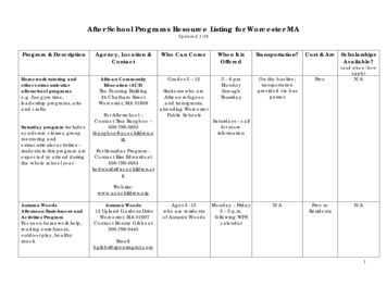
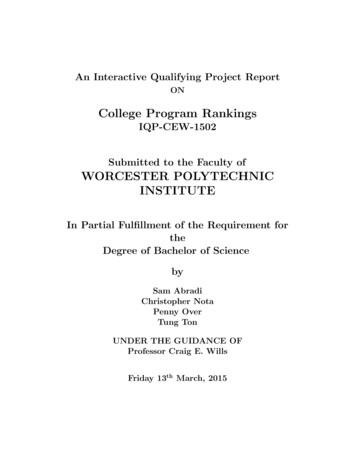
Executive SummaryOne of the most sophisticated technological advances on our planet has become a crucial part ofeveryday human life. The progression and development of the automobile has led to an increase in thedangers related to its operation. Today’s modern vehicles are equipped with many devices that helpprevent serious injury in the event of a crash, or help avoid an accident all together. Most averagedrivers may recognize the names of some common safety devices in their vehicle, but many lack theknowledge of how these devices effectively work in providing them with a safe driving experience eachday.The Objective: The primary objective of this project is to educate the public on the history, purpose, andtechnology of common safety devices of modern automobiles.Project ConceptThe concept is to create a museum-like kiosk, in which several select safety devices are affixed tothis display. Images depicting the rendition of our project concept are shown below in Figures 1 & 2.Figure 1 – 3-Dimential Artist RenditionFigure 2 – 2-Dimential DiagramThey key feature of this project concept incorporates the display of actual automobile safetydevices. These devices will serve the purpose of allowing a user to touch and visualize each device in itstrue-form. A monitor screen driven by a hidden computer will display relevant information in the formof videos, diagrams, audio tracks, etc. Each device will be represented by a user-triggered button thatwill activate the presentation to focus on that particular chosen system.Page xi
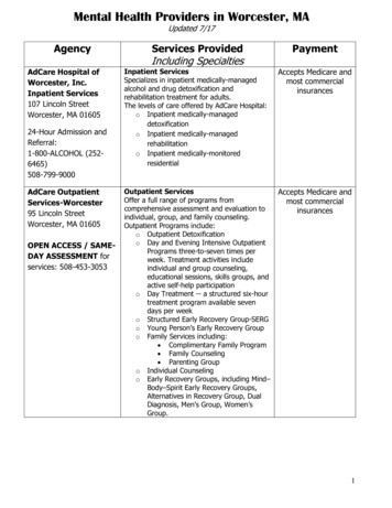
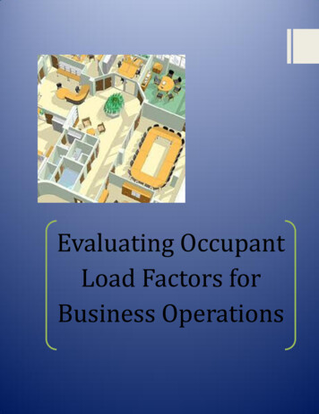
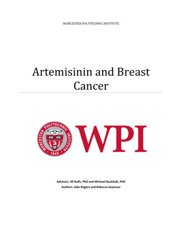
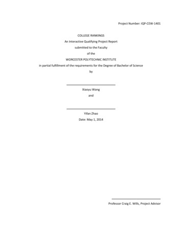
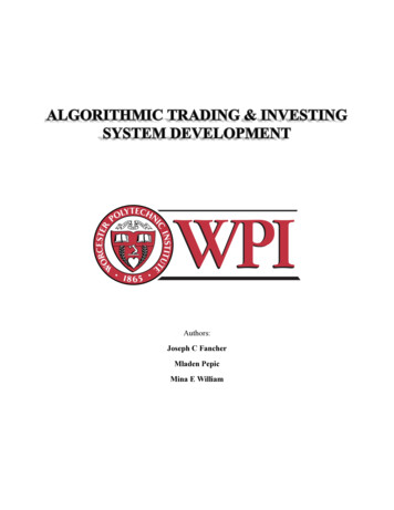
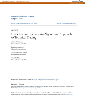
The PresentationFor the educational presentation, several safety devices were chosen to educate the community ontheir History, Purpose, and Functionality in modern automobiles.The Seatbelt SystemThe Seatbelt System was chosen for its importance in automobile safety,despite its simplicity. The Seatbelt has become one of the oldest automobilesafety devices that are still used today. It plays a crucial role in the safety ofits occupant during the operation of a vehicle. The Seatbelt has become farmore than just a belt used to restrain an occupant during an automobilecollision. The seatbelt system has developed through the years to become apart of the Safety-Restraint System (SRS), which works in effort with theAirbag system to minimize the risk of fatal injury during an automobileFigure 3 – Typical Seatbeltaccident.The Airbag SystemThe Airbag System has become a major technologicaladvancement in the automotive history. The effectiveness ofthe Airbag in an automobile collision has made thistechnology a standard in all modern vehicles producedtoday. It works in tandem with the Seatbelt System to formthe Safety-Restraint System (SRS), which minimizes the riskFigure 4 – Airbag Crash Testingof fatal injury during an automobile accident.The Anti-Lock Braking SystemThe Anti-Lock Braking System is a safety system designed toprevent the wheels of a motor vehicle from locking up whilebreaking. It functions by rapidly applying a brake on and off in theevent of wheel lockup. It utilizes the Engine Control Unit (ECU) alongwith sensors in each wheel to detect and decide when to apply antilock braking to a wheel.Figure 5 – Brake PedalPage xi
Headlights, Turn Signals, & Crumple ZonesHeadlights function to illuminate the road in front of anautomobile when visibility is limited. They are a crucial componentto the safe operation of automobiles when visibility is limited.Advancements in headlight technology have led to adaptiveheadlights, which adjust the angle of the beams to upcoming curveson a road. Turn signals function to alert other automobiles of anupcoming change in direction of your automobile. They areessentially headlights that flash when activated until a turncompletion is detected. Crumple Zones function to redistributeenergy from a collision away from occupants. They were asignificant development in preventing serious injury to occupantsduring a collision by collapsing, crumpling, deforming, and crushingon impact.Figure 6 – Crumple Zone TestingElectronic Traction & Stability ControlThe Electronic Traction Control System functions to keep automobile wheels from losing tractionwhen accelerating. It is the Anti-Lock Braking System applied to acceleration rather than braking. It iscontrolled by the ECU and shares sensors andcontrol mechanisms with the ABS. The e stays on its intended path throughturns. It utilizes the Anti-Lock Braking System toprevent skidding during turns as well aspotential rollovers. Both of these systems areFigure 7 – Electronic Traction Control Testingmodern automobile safety achievements thathave significantly reduced automobile collisions.Page xii
The Display PlatformTo effectively portray the technology behind the various safety devices used in modernautomobiles, an exhibit has been constructed to display key-pieces of these safety devices along withthe visual-presentation to enhance the user’s learning experience.The DesignThis project consisted of both a physical exhibit featuring various automobile safety devices anddigital presentations to educate users on these devices. The physical exhibit was constructed fromplywood and featured safety devices mounted on it along with graphics and buttons. A monitor andspeaker were also mounted which displayed presentations based on buttons pressed near theircorresponding physical safety devices. The exhibit was painted and finished to museum quality ensuringit would be of appropriate quality for any venue.The presentations were created using the Adobe Flash platform. Scripts were written andcontent collected/created to go along with the scripts. These were then arranged into digitalpresentations to educate users while keeping them engaged. The presentations were linked togetherusing ActionScript 3.0 such that they could be controlled by the physical buttons on the exhibit. Inaddition to the presentations, and introductory animation was created to attract users to the exhibitwhen it is not in use.FunctionalityThis exhibit required extensive hardware and software designs to function. An interfacebetween the buttons and computer had to be created so that the buttons could control thepresentations displayed on the computer. Multiple functions in ActionScript 3.0 were written to handlebutton input key presses and perform the tasks of loading and unloading them. The computer was setup to automatically launch the presentations upon a restart as well as log all key presses so that usagedata could be analyzed. All electrical components were hardwired to a single switch so that the exhibitcould be easily turned on and off when necessary.Page xiii
Project ResultsTo quantify the success of our project and analyze usage data all button presses were logged aswell as a survey distributed to gain feedback from users.Results & AnalysisOver the course of 140 days a total of 1142 button presses were logged. These correspond toviewings of individual presentations. The top three automobile safety devices of interest were Airbags,Lights & Crumple Zones, and Electronic Traction & Stability Control. The least triggered presentationswere Brakes and Seatbelts. These results may be due to users familiarity with Brakes and Seatbelts overthe other safety devices and their relative complexities of operation. This exhibit has shown it self to bepopular amongst the WPI community even during the quieter summer months based on this usage data.Community FeedbackFeedback from the WPI community has been incredibly positive. A survey was conducted togather feedback formally. One particular recommendation came from one of the librarians:“It is prom time as well as graduation time at local high schools, so the message to NOT DRINKAND DRIVE would have been nice (or at least a few scary videos showing crashes).”Another comment received from another member of the WPI community said:“This is a super project. I can see use in Driver’s Ed programs, police road safety, etc.”This could be a possible variation with this type of project – deploying an interactive educationalplatform in safety programs. Another comment and recommendation provided by a graduate student ofthe WPI community said:“I think that some visitors were impressed to see this IQP in the library, especially those whowere families with prospective students. I do think some considerations for accessibility may beconsidered if a future similar project were done or if this were installed in a museum (height ofexhibit not ADA compliant, also since there are many parts/videos, perhaps a chair, where 2could sit and interact with the display).”In response to this, there were many valuable lessons learned during the course of this project. Oneparticular lesson includes re-evaluating and casting size limitations on such a display exhibit. Onepossibility is the design of a table-top system that can be moved amongst various locations.Page xiv
Chapter 1: IntroductionOne of the most sophisticated technological advances on our planet has become a crucial partof everyday human life. The progression and development of the automobile has led to an increase inthe dangers related to its operation. Today’s modern vehicles are equipped with many devices that helpprevent serious injury in the event of a crash, or help avoid an accident all together. Most averagedrivers may recognize the names of some common safety devices in their vehicle, but many lack theknowledge of how these devices effectively work in providing them with a safe driving experience eachday.1.1 Primary ObjectivesBased on the problem statement described above, a list of objectives has been determined tooutline this project and provide a viable sol
advancement in the automotive history. The effectiveness of the Airbag in an automobile collision has made this technology a standard in all modern vehicles produced today. It works in tandem with the Seatbelt System to form the Safety-Restraint System (SRS), which minimizes the risk of fatal injury during an automobile accident.