Transcription
User GuideTracer TD7 with UC 800for RTHD chillersRLC-SVU006A-E4Original instructions
CopyrightAll rights reservedThis document and the information in it are the property of Trane and may not beused or reproduced in whole or in part, without the written permission of Trane.Trane reserves the right to revise this publication at any time and to make changesto its content without obligation to notify any person of such revision or change.TrademarksTD7, RTHD Trane, the Trane logo, and Tracer are trademarks of Trane. All trademarksreferenced in this document are the trademarks of their respective owners.2 2014 TraneRLC-SVU006A-E4
Table of ContentsGeneral Recommendations . 4Units with Nitrogen Charge Option . 5Installer-Supplied Components. 5Power Supply Wiring . 5Control Power Supply . 5Motor Cable . 6Motor Rotation Check . 6AC Mains Connection . 6Interconnecting Wiring . 7Chilled Water Pump Control . 7Programmable Relays . 7Relay Assignments Using Tracer TU . 9Low Voltage Wiring . 9Emergency Stop . 9External Auto/Stop . 9Ice Building Option . 10External Chilled Water Setpoint (ECWS) Option. 10External Demand Limit Setpoint (EDLS) Option . 10EDLS and ECWS Analog Input Signal Wiring Details: .11Chilled Water Reset (CWR) .11Communications Interface . 12LonTalk Interface (LCI-C) . 12BACnet Protocol . 12BACnet Testing Laboratory (BTL) Certification. 12Modbus RTU Protocol. 12Overview . 13UC800 Specifications . 13Wiring and Port Descriptions . 13Communication Interfaces . 13Rotary Switches. 13LED Description and Operation . 13Tracer TD7 Operator Interface . 14Tracer TU . 14Starter Diagnostics . 17Main Processor Diagnostics . 20Communication Diagnostics . 26Operator Display Diagnostics and Messages . 29RLC-SVU006A-E43
Installation ElectricalGeneral RecommendationsAs you review this manual, keep in mind that: All field-installed wiring must conform to Europeanguidelines and any applicable local codes. Be sure tosatisfy proper equipment grounding requirements perEuropean guidelines. Compressor motor and unit electrical data (includingmotor kW, voltage utilization range, rated load amps)is listed on the chiller nameplate. All field-installed wiring must be checked for properterminations, and for possible shorts or grounds.WARNINGHazardous Voltage - Pressurized Burning Fluid!Before removing compressor terminal box cover forservicing, or servicing power side of control panel,CLOSE COMPRESSOR DISCHARGE SERVICE VALVEand disconnect all electric power including remotedisconnects. Discharge all motor start/run capacitors.Follow lockout/tagout procedures to ensure thepower cannot be inadvertently energized. Verify withan appropriate voltmeter that all capacitors havedischarged.Note:: Always refer to wiring diagrams shipped withchiller or unit submittal for specific electricalschematic and connection information.The compressor contains hot, pressurized refrigerant.Motor terminals act as a seal against this refrigerant.Care should be taken when servicing NOT to damage orloosen motor terminals.WARNINGDo not operate compressor without terminal box coverin place.Proper Field Wiring and Grounding Required!All field wiring MUST be performed by qualifiedpersonnel. Improperly installed and grounded fieldwiring poses FIRE and ELECTROCUTION hazards. Toavoid these hazards, you MUST follow requirements forfield wiring installation and grounding as described inlocal electrical codes. Failure to follow code could resultin death or serious injury.WARNINGHazardous Voltage w/Capacitors!Disconnect all electric power, including remotedisconnects and discharge all motor start/run and AFD(Adaptive Frequency Drive) capacitors before servicing.Follow proper lockout/tagout procedures to ensure thepower cannot be inadvertently energized.Failure to follow all electrical safety precautions couldresult in death or serious injury.For additional information regarding the safe dischargeof capacitors, see “Adaptive Frequency Drive (AFD3)Capacitor Discharge,” p. 28 and PROD-SVB06A-EN.NOTICE:Use Copper Conductors Only!Unit terminals are not designed to accept other typesof conductors. Failure to use copper conductors couldresult in equipment damage.Important::To prevent control malfunctions, do not runlow voltage wiring ( 30 V) in conduit withconductors carrying more than 30 volts. For variable frequency drives or other energy storingcomponents provided by Trane or others, refer to theappropriate manufacturer’s literature for allowablewaiting periods for discharge of capacitors. Verifywith an appropriate voltmeter that all capacitors havedischarged. DC bus capacitors retain hazardous voltages afterinput power has been disconnected. Follow properlockout/tagout procedures to ensure the power cannotbe inadvertently energized. After disconnecting inputpower, wait five (5) minutes for the DC capacitors todischarge, then check the voltage with a voltmeter.Make sure DC bus capacitors are discharged (0 VDC)before touching any internal components.Failure to follow these instructions could result in deathor serious injury.For additional information regarding the safe dischargeof capacitors, see “Adaptive Frequency Drive (AFD3)Capacitor Discharge,” p. 28 and PROD-SVB06A-EN.4RLC-SVU006A-E4
Installation ElectricalIn case of drive servicing onlyPower Supply WiringWARNINGDISCHARGE TIME!WARNINGFrequency converters contain DC-link capacitors thatcan remain charged even when the frequency converteris not powered. To avoid electrical hazards, disconnectAC mains, any permanent magnet type motors, andany remote DClink power supplies, including batterybackups, UPS and DC-link connections to otherfrequency converters. Wait for the capacitors to fullydischarge before performing any service or repair work.The amount of wait time is listed in the Discharge Timetable. Failure to wait the specified time after power hasbeen removed before doing service or repair could resultin death or serious injury.Proper Field Wiring and Grounding Required!Table 1. Capacitor Discharge TimesVoltagePowerMinimum waitingtime [min]380-500 V90-250 kW20315-800 kW40All field wiring MUST be performed by qualifiedpersonnel. Improperly installed and grounded fieldwiring poses FIRE and ELECTROCUTION hazards. Toavoid these hazards, you MUST follow requirements forfield wiring installation and grounding as described inyour local electrical codes. Failure to follow code couldresult in death or serious injury.All power supply wiring must be sized and selectedaccordingly by the project engineer in accordancewith EN 60204.All wiring must comply with local codes. The installing(or electrical) contractor must provide and install thesystem interconnecting wiring, as well as the powersupply wiring. It must be properly sized and equippedwith the appropriate fused disconnect switches.The type and installation location(s) of the fuseddisconnects must comply with all applicable codes.NOTICE:Units with Nitrogen Charge OptionFor units with nitrogen charge option (model numberdigit 15 2), the unit must NOT have shore power, orunit power applied until the unit has been charged.Applying power will drive EXV valves closed, and willinhibit sufficient vac for unit charging.Installer-Supplied ComponentsCustomer wiring interface connections are shown inthe electrical schematics and connection diagrams thatare shipped with the unit. The installer must provide thefollowing components if not ordered with the unit: Power supply wiring (in conduit) for all field-wiredconnections. All control (interconnecting) wiring (in conduit) forfield supplied devices. Fused-disconnect switches or circuit breakers.Use Copper Conductors Only!Unit terminals are not designed to accept other typesof conductors. Failure to use copper conductors couldresult in equipment damage.Cut holes into the sides of the control panel for theappropriately-sized power wiring conduits. The wiringis passed through these conduits and connected to theterminal blocks, optional unit-mounted disconnects, orHACR type breakers.The high voltage field-provided connections are madethrough patch plate on the right side of the panel. Thelow voltage connections are made through knockoutsprovided on the left side of the panel. Additional groundsmay be required for each 115 volt power supply to theunit. Green lugs are provided for 115V customer wiring.Control Power SupplyThe unit is equipped with a control power transformer.It is not necessary to provide additional control powervoltage to the unit. No other loads should be connectedto the control power transformer.All units are factory-connected for appropriate labeledvoltages.RLC-SVU006A-E45
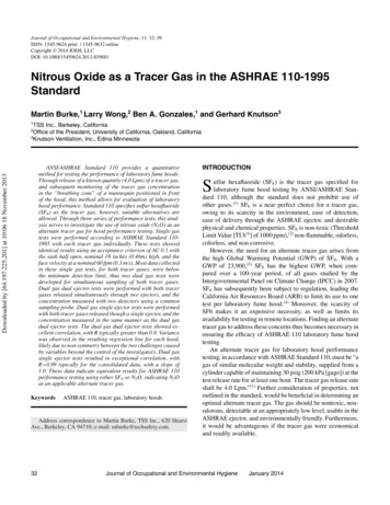
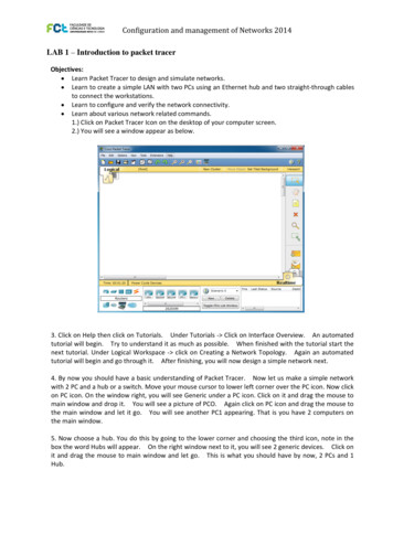
Installation ElectricalFigure 1. Connecting to AC MainsMotor CableThe motor must be connected to terminals U/T1/96, V/T2/97, W/T3/98. Earth (ground) to terminal 99. All types ofthree-phase asynchronous standard motors can be usedwith a frequency converter unit. The factory setting is forclockwise rotation with the frequency converter outputconnected as follows:Table 2.Terminal no.Function96, 97, 98, 99Mains U/T1, V/T2, W/T3Earth (ground)Motor Rotation CheckThe direction of rotation can be changed by switchingtwo phases in the motor cable or by changing the settingof 4-10 Motor Speed Direction.Table 3. Terminal U/T1/96connected to U-phase Terminal V/T2/97connected to V-phase Terminal W/T3/98connected to W-phaseTable 4.A motor rotation check can be performed using1-28Motor Rotation Check and following the steps shown inthe display.AC Mains Connection Size wiring is based upon the input current of thefrequency converter Comply with local and national electrical codes forcable sizes Connect 3-phase AC input power wiring to terminalsL1, L2, and L3 (see Figure 1)61Mains connection2Motor connection Earth (ground) the cable in accordance with theinstructions provided All frequency converters may be used with an isolatedinput source as well as with earth (ground) referencepower lines. When supplied from an isolated mainssource (IT mains or floating delta) or TT/TN-S mainswith
cable sizes † Connect 3-phase AC input power wiring to terminals L1, L2, and L3 (see Figure 1) Figure 1. Connecting to AC Mains Table 4. 1 Mains c onnecti n 2 Motor connection † Earth (ground) the cable in accordance with the instructions provided † All frequency converters may be used with an isolated