Transcription
Packet Tracer NetworkSimulation2020Extracted from cisco public documents
Packet Tracer – Network SimulationContentsLesson 1 Getting Started .3Part 1 Introducing the workspace .4Part 2 Creating a simple network . 11Part 3 Configuring the Network . 15Lesson 2 Exploring a Network . 18Open file 2.1 Packet Tracer - Navigating the Internetwork Operating System (IOS) . 18Part 1: Basic Connections, Accessing the CLI and Exploring Help . 19Part 2: Exploring EXEC Modes . 21Part 3: Setting the Clock . 23Lesson 3 Configuring Network Devices . 27Open file 3.1 Packet Tracer - Configuring Initial Switch Settings . 27Part 1: Verify the Default Switch Configuration . 28Part 2: Create a Basic Switch Configuration . 29Part 3: Configure a MOTD Banner . 34Part 4: Save Configuration Files to NVRAM . 34Part 5: Configure S2 . 35Lesson 4 Configuring Connectivity . 36Open file 4.1 Packet Tracer - Implement Basic Connectivity . 36Part 1: Perform a Basic Configuration on S1 and S2 . 38Part 2: Configure the PCs. 39Part 3: Configure the Switch Management Interface . 40Open file 4.2 Packet Tracer - Skills Challenge. 42Lesson 5 Investigating TCP/IP and OSI . 43Open file 5.1 Packet Tracer - Investigating the TCP/IP and OSI Models in Action . 43Part 1: Examine HTTP Web Traffic. 44Part 3: Display Elements of the TCP/IP Protocol Suite . 47Part 4: Test End-to-End Connectivity with the tracert Command . 49Open file 5.2 Packet Tracer - Testing Connectivity with Traceroute . 492
Packet Tracer – Network SimulationLesson 1 Getting StartedIntroductionPacket Tracer (PT) is a network simulation package. It represents a learning environment for use inthe exploration of the design and analysis of computer networks. It is based around a simple buteffective model of networking devices and associated protocols. (It is not a replacement for thehands-on experience which can only come from the investigation of real systems obtained in thelabs.)In this sequence of activities, we concentrate on the processes required when developing models ofnetworks. The student should note that the package is much more than a simple model networkdevelopment tool; the simulation aspects of the package are explored in a different series ofactivities.ObjectivesPart 1: Introducing the workspacePart 2: Creating a simple networkPart 3: Configuring the network3
Packet Tracer – Network SimulationPart 1 Introducing the workspaceIn this activity we get the Packet Tracer (PT) program up and running. Then we place a model PC intothe workspace and look at some of the options available with it.Step 1: Starting PTIf the following PT iconPacket Tracer version 6.0.1.0011is showing on the desktop then double-click on it. Alternatively, look for the package under‘start/all programs’. If this does not work try appsanywhere.After you have the program running, the first screen – shown in diagram 1- will be displayed. Checkthat the Realtime tab towards the bottom right of the window (see diagram 1) is on top of theSimulation tab – if the simulation tab is showing then click the tab behind to bring the Realtime tab tothe fore.4
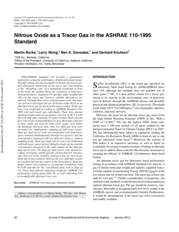
Packet Tracer – Network SimulationFor the first few activities we will be concentrating on the icons found towards the bottom left ofthis opening screen.Step 2: Load a virtual computer into the workspaceLook at the bottom left hand side of the PT window; there is a group of icons presented there, asshown in the next diagram.The icons in the group indicate the range of devices that can be represented in a PT simulation. Theiconat the bottom left of this group represent potential end devices for the network (PCs,Printers, Phones and Servers). Click on this icon and note that the box adjacent to it takes thefollowing form.The displayed icons represent (from left to right) a computer, a laptop, a server, a printer, aphone Scroll along this bottom part of the screen to see the other end devices.To introduce a computer into the simulation click on theicon and then click on the work area. Apicture of the computer icon should appear in the main screen, with the symbolsappearing beneath it.5
Packet Tracer – Network SimulationThe top PC indicates personal computer; the adjacent PT refers to Packet Tracer. The symbols on thesecond row are the name assigned to this PC (i.e. PC0) this name can be changed to suit the user (seelater).6
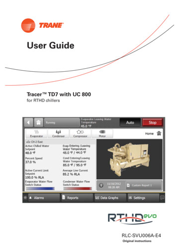
Packet Tracer – Network SimulationStep 3: Investigating the PCThe personal computer in the window is more than a simple graphic: it models the behaviour of a PCwell enough to demonstrate behaviour relevant to network modelling. To see this, click on the PC. Youshould see the following (don’t worry if you haven’t got this – it will be a minor error: check that youhave created a PC and not some other PT object)Note the current name of the PC is displayed at top left (in our case the default, PC0, as supplied bythe program). Below this name are four tabs:The currently selected tab is the Physical one, as can be seen from its different background. Observethe button halfway down and to the right of the PC image, with the green indicator light above it.This is an On/Off switch for the device – the default is for the device to be on. Click the switch andyou will observe that the machine becomes switched off. Make sure that the device is switched onbefore proceeding.7
Packet Tracer – Network SimulationClick on the Config and Desktop tabs and have a look at what is displayed.Select the Desktop tab. You should have a screen like the following.The desktop offers some of the tools you might expect from a personal computer. The following gives apartial screen shot of the command prompt.Try typing ipconfig at the prompt. You will see that the computer is not currently configured with an IPaddress. The PT simulation of a computer is limited to functions that are useful when modelling anetwork. Try the arp –a command (this will be empty since we are not connected to a network yet.).8
Packet Tracer – Network SimulationClose the command prompt using thein the top right of the Command Prompt box – this will takeyou back to the PCs desktop. (Note if you type the cross at the very top right of the widget, i.e.,then the model computer interface will close – don’t worry, you can open it again by double clicking onthe icon.).Step 4 : Revisiting the PCClose the interface to the PC (you should return to the opening screen with the placed PC on it). Letthe cursor rest on the PC icon and you will get an information box displayed like the following.The information in the box is limited – we have not set an IP address, gateway and DNS server yet.Though the MAC address for the PC’s NIC card is displayed to the top right.Further information about the PC (and other simulated devices) can be obtained by clicking theicon found to the right of the main screen, and then clicking on the device. For the PC the only optionis the ARP table and this is currently empty. (For routers and switches this is easily accessibleinformation about the device – though the information can be obtained more ‘conventionally’ fromthe simulated object using the device interface!)Before progressing return to the PCs Command Prompt (on the Desktop): the material you typed in isstill there! The device behaves like a real device – the information is retained.Now click on the IP Configuration tab. You will be taken to a window as shown in the following.This is the PT equivalent to the GUI that is used by Windows to assign IP addresses etc.9
Packet Tracer – Network SimulationLet us configure the PC using this GUI. (Strictly speaking we don’t really need to use the form since oursingle computer is not connected to anything). Click on the IP Address box and input 1.0.0.2. Clickon the Subnet Mask; you will get a proposed mask just accept this for the time being. Click on theDefault Gateway and enter 1.0.0.1. Leave the DNS Server for the time being.Come out of the PC and float the cursor over the icon again and you will see the information thatyou have input displayed.TaskIntroduce a printer, a telephoneand a serverinto the logicalworkspace. Take a look at the Physical, Config and Desktop (server) interfaces to the devices.Try switching them On and Off (not the phone - no switch).Note that all of the devices have options to assign IP addresses. A requirement for anyend device on a networkExit PT before starting the next activity. This ensures that any changes you have made will not becarried over into the next activity and the package starts in the standard mode.10
Packet Tracer – Network SimulationPart 2 Creating a simple networkIn this activity we will introduce two computers and then connect them up. We will check connectivityusing the ping command. We will also introduce some new aspects of PT as we go; in particular, we willrename PCs and configure them with IP addresses.Step 1: Configuring the networkIntroduce two PCs into the workspace – click on the end devices icon (see Activity 1) then click on theworkspace. Then repeat for the second PC. Make sure they are a couple of inches apart – note you canmove them by: click, hold and drag the icon.The two PCs will be named PC0 and PC1 We will rename the two PCs as ‘my comp’ and ‘your comp’. Todo this click on the PC icon and select the Config tab. Just under the Global Settings header there is aninput tool entitled Display Name. On one PC Type the name ‘my comp’ at the input tool (no invertedcommas) and then name the other PC ‘your comp’ on the other machine.To connect the two machines we need a copper crossover cable: click theicon found in the bottomleft group (this icon represents connectors). The box to the left will change to appear as follows. Notethe icons represent different connection media, and there are more than are displayed as can be seenby using the slider bar.To select copper cross-over: move over the icons and note that the type of the connector is recorded inthe text box at the bottom of this group, and note the type. The one we want is represented by.Click on theicon and move onto the workspace. The cursor will change to a graphic representinga wire with a connector. To attach the wire to a computer click on it. The following box will appearnext to the PC:Click on the FastEthernet button (equivalent to attaching one end of the wire to the NIC on the PC).Now move the cursor over the other PC. (You will notice a wire graphic, extending from the first PC11
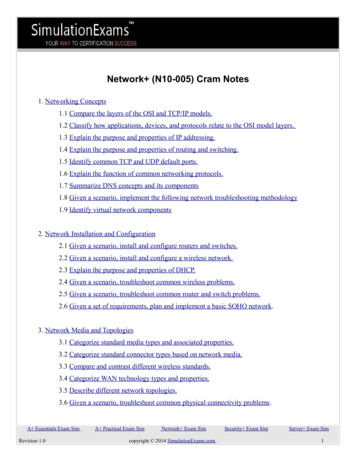
Packet Tracer – Network Simulationand moving with the cursor.) Click on the new PC and the same box as before will appear. Again, clickon the FastEthenet button.The current state of the window should have a network image in the logical workspace something like:Representing two PCs connected by a copper cross-over cable via their FastEthernet ports.Step 2 : Configuring IP addressesThe two PCs are connected but they cannot ‘speak’ to each other until they have IP addressesassigned.Go into the Desktop of each PC and choose the IP configuration program which will bring upthe following box.12
Packet Tracer – Network SimulationIn the ‘my comp’ input the IP address 1.0.0.1 and click in the Subnet Mask e
Open file 4.2 Packet Tracer - Skills Challenge . Open file 5.2 Packet Tracer - Testing Connectivity with Traceroute. 49 . Packet Tracer – Network Simulation 3 Lesson 1 Getting Started . Introduction. Packet Tracer (PT) is a network simulation package. It represents a learning environment for use in the exploration of the design and analysis of computer networks. It is based around a .