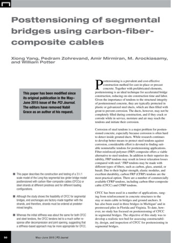
Transcription
Posttensioning of segmentalbridges using carbon-fibercomposite cablesXiong Yang, Pedram Zohrevand, Amir Mirmiran, M. Arockiasamy,and William PotterThis paper has been modified sinceits original publication in the May–June 2015 issue of the PCI Journal.The editors have removed NabilGrace as an author at his request. This paper describes the construction and testing of a 31 2:1scale model of the Long Key segmental box girder bridge modelposttensioned with carbon-fiber-composite cables (CFCCs) orsteel strands at different prestress and for different loadingconfigurations. Although the study shows the feasibility of CFCC for segmentalbridges, end anchorages are factory-made together with thestrands, and therefore, strands must be ordered at predetermined lengths. Whereas the initial stiffness was about the same for both CFCCand steel tendons, the CFCC tendons led to a much softer response after decompression and joint opening, suggesting thata stiffness-based approach may be more appropriate for CFCC.50May – J u n e 2 0 1 5 PCI JournalPosttensioning is a prevalent and cost-effectiveconstruction method for cast-in-place or precastconcrete. Together with prefabricated elements,posttensioning is an ideal technique for accelerated bridgeconstruction, reducing on-site construction time and labor.Given the importance of tendons to the structural integrityof posttensioned concrete, they are typically protected inplastic or galvanized steel ducts, which are then filled withgrout to prevent corrosion. The ducts, however, may not becompletely filled during construction, and if they crack orcorrode while in service, moisture and air may reach thetendons and initiate their corrosion.Corrosion of steel tendons is a major problem for posttensioned concrete, especially because corrosion is often hardto detect inside grouted ducts. While research continuesto develop better means to protect steel tendons againstcorrosion, considerable effort is devoted to finding suitable nonmetallic tendons for posttensioning applications.Fiber-reinforced-polymer (FRP) composite offers a viablealternative to steel tendons. In addition to their superior durability, FRP tendons may result in lower relaxation lossescompared with steel.1 FRP tendons may be made withdifferent types of fibers, such as carbon, glass, aramid, orbasalt. Due to their higher strength, elastic modulus, andexcellent durability, carbon FRP (CFRP) tendons are themost practical option. There are a number of commerciallyavailable CFRP tendons, including carbon-fiber-compositecable (CFCC) and CFRP tendons.CFCC has been used in a number of applications, ranging from reinforcement in concrete structures to thestay or main cable in bridges and ground anchors. Ithas also been used in three bridges in Michigan2 and inprestressed piles in Florida and Virginia. To date, however, no study has focused on posttensioning of CFCCin segmental bridges. The objective of this study was todevelop a realistic test bed for assessing constructability, design, and inspection of CFCC for posttensioning insegmental bridges.
Review of literatureA number of studies have focused on posttensioning applications of CFCC. Two half-scale precast, prestressedconcrete box-beam bridge superstructure specimens, onewith CFCC tendons and the other with conventional steelstrands, were tested by Grace et al.3 to assess their performance in flexure. Both models exhibited similar behaviorirrespective of the type of strand used. Grace et al.4 studiedthe flexural behavior of a full-scale, double-tee beamprestressed using bonded pretensioned CFRP tendons andunbonded posttensioned CFCC tendons. Strain distributionalong the beam section, deflection, cracking load, tensioning, ultimate load-carrying capacity, and failure mode wereinvestigated. The specimens showed considerable strengthbeyond service load. The results of this study were appliedto the design of the double-tee beams used in the construction of the Bridge Street Bridge2 in Southfield, Mich.Grace et al.5 tested three bridge models in flexure up tofailure. The three models included unbonded, posttensioned CFCC tendons; unbonded CFCC tendons with zeroposttensioning force; and no unbonded CFCC tendons. Thesame number of bonded pretensioned and bonded nonprestressed CFCC tendons was used for each model. Testresults showed that the specimen with the higher prestressing force would fail in a sudden and brittle mode, whereasspecimens with lower prestressing force would fail gradually. The additional unbonded CFCC posttensioning forcedelayed the development of cracks and reduced the numberand size of cracks, as well as the residual deflections.Fatigue behavior of concrete structures prestressed withCFRP has also been studied. Dolan et al.1 reported thatcracked CFRP prestressed concrete beams did not showany sign of fatigue failure after 3 million cycles of flexural loading, though cracking was observed after the firstmillion cycles. The beams did not lose any strength dueto fatigue even though a gradual softening was observed.Grace et al.6 investigated the performance of a continuousCFRP prestressed concrete bridge under 15 million cyclesof repeated loads. In this study, there was no significanteffect on the prestressing force of externally draped posttensioning tendons. Similarly, no sign of damage in CFRPtendons was observed at the deviators.Long-term performance assessment of FRP tendons inbridges is necessary. A comprehensive structural-healthmonitoring of highway bridges consists of four steps:7 Limited data are available on the implementation of anintegrated monitoring system for FRP tendons.2,8 Availablenondestructive methods with potentials for inspection ofFRP prestressed concrete structures include visual, reflective, imaging, and load testing.Visual inspection of CFCC tendons could be easilyimplemented using a borescope but may only offer limitedinsight as to their performance. Reflective methods relyon transmitting various forms of sonic waves and investigating their return response. Most reflective methodsare suited for investigating local and small areas and aregenerally time-consuming if conducted on a point-by-pointbasis. The acoustic-emission technique, which effectivelylistens for wire breaks, has been used for monitoring posttensioned and prestressed concrete bridges. Nondestructive techniques in the imaging category allow for a moredetailed visual inspection. They include radiographic imaging or tomographic systems. In general, these techniquesare difficult and expensive to implement in field conditionsand are often applicable to small areas. Finally, structuralelement characteristics can be determined via global loadtesting. Installation of fiber-optic sensors (at the time ofconstruction) or load cells to monitor stress along CFCCtendons is perhaps the most reliable technique for inspection and monitoring of CFCC.Even though segmental bridge construction is popular inpractice, only a few experiments have been carried out onthese types of bridges, and none with CFCC tendons. Acomprehensive study9 investigated the behavior of a threespan external posttensioned concrete box-girder bridgemodel with different types of joint connections, includingdry joints and epoxy joints. The bridge model was testedunder service loads, factored loads, and ultimate loads fordifferent loading configurations, all of which could resultin maximum flexure and maximum shear. Test resultsdemonstrated that the epoxy joints could help prevent jointopening and limit bridge deflections. Also, the performance of a scaled single-cell precast concrete posttensioned segmental box-girder bridge model with dry jointssubjected to cyclic loading and temperature changes wasinvestigated.10 Joint opening and cracking were found negligible up to 2 million load cycles. Temperatures did notseem to make much difference across the section either.Experimental programSpecimen preparationand erection processsensor placement and measurement structural identification and modeling damage detection and degradation assessment decision-making on rehabilitation and maintenanceA simple-span 1:31 2-scale superstructure model of theLong Key segmental box-girder bridge in the Florida Keyswas constructed as a test bed for a series of experiments tocompare posttensioning with CFCC and steel strands. Consistent with the prototype bridge, the model was designedbased on the American Association of State Highway andPCI Journal M a y– J u n e 201551
Transportation Officials’ (AASHTO’s) Standard Specifications for Highway Bridges.11 In the 1990s, Arockiasamyet al.10 had used a similarly scaled model of the sameprototype, as described earlier. Figure 1 shows the bridgemodel consisting of seven trapezoidal box-girder segmentsand two solid end blocks with a rectangular section. Thetendons were harped at a 5 angle with contacts limited tothe end blocks, and the two deviators in the two segmentswere placed adjacent to the center segment. Each deviatorwas designed as a beam to resist uplift at the harping point.The solid end blocks were designed to resist the prestressingforce. The segments were connected as dry joints with multiple shear keys along both flanges and webs. Each segmentwas reinforced using 1 4 in. (6 mm) diameter steel bars with ayield strength of 60 ksi (410 MPa) spaced at 31 2 in. (89 mm)on center in both longitudinal and transverse directions.Figure 2 shows the fabrication process for the bridgemodel. Wooden formwork was assembled for the entirebridge model to match cast the segments. Styrofoam wasused to create hollow-cores of box-girder sections and thejoint shear keys on both flanges and webs of each segment. Foam blocks of each pair of segments were matchedwith the divider foam, interlocking the tongue and groovesthat were precut on their surfaces. The pieces of foamwere bonded using foam glue. Spacers were made using aFigure 2. Formwork for segmental bridge model.52May – J u n e 2 0 1 5 PCI JournalFigure 1. 1:31 2 scale model of Long Key Bridge. Note: 1 in. 25.4 mm; 1 ft 0.305 m.circular plate tack welded at one end of a screw to supportthe foam and to control the thickness of the bottom flangeand the webs (Fig. 2). Formwork and the template weredesigned and built for each anchorage zone to accuratelyand firmly support the posttensioning ducts and steel plates
Table 1. Geometric and material properties CFCC and steel strandsat the exact 5 harping angle. The posttensioning ductswithin the end blocks were made using a cardboard tubethat is supported between the anchorage block and the firstfoam divider (Fig. 2 upper right). A boom pump facilitated casting of the entire bridge model and its supportsusing a self-consolidating concrete with a compressivestrength of 8630 psi (59.5 MPa) as measured at the timeof testing from at least three companion cylinders. Thesegments were de-molded a week after casting. The foamswere carefully removed from within each segment usingacetone. The segments were then erected side by side withtemporary wooden stands before tensioning.PosttensioningTable 1 lists the geometric and material properties of thetwo types of strands used for posttensioning the bridgemodel, as reported by their manufacturers. CFCC tendonsare made as seven-wire twisted cables similar to typicalsteel strands and are available in diameters up to 1.57 in.(40 mm). They are guaranteed in strengths up to 241 kip(1070 kN). For the bridge model, 0.49 in. (12.5 mm) diameter CFCC tendons were used to closely match the 1 2 in.(13 mm) diameter, seven-wire low-relaxation steel stands.CFCC tendons are shipped as coiled strands with prefabricated special end anchorages. Although regular chuckanchoring devices for steel tendons are widely available,cost-effective, and reliable, they cannot be applied directlyto CFCC tendons because of the brittleness of the cablesunder transverse-gripping pressure. The anchorage systemfor CFCC tendons is a factory-made steel sleeve filled witha proprietary resin. The sleeve has internal threads to facilitate posttensioning using a threaded-steel rod and externalthreads using a circular nut to help lock the prestressingforce. This system does not easily accommodate deviationsfrom the preordered lengths, whether due to constructiontolerances or miscalculation in the elongation of the cable.Any such deviation may require abandoning the cableentirely or having to develop a build-up at the jacking endto make up for the difference.Cables in the bridge model were protected at both endsand at the two deviators by using flexible reinforcedbraided-PVC tubes as jackets. A 1 2 in. (13 mm) thickneoprene pad was placed atop the cables at each harpingpoint in the deviators to avoid potential damage at sharpcorners. The four cables on each side of the model werepassed through the segments before placing the end blockon the south side of the model, which effectively closedoff the system.From the constructability perspective, the most feasibleoption for simultaneous posttensioning of multiple cablesis to develop a super coupler that transfers the forcesfrom the sleeves of multiple CFCC tendons on one sideto regular steel strands on the other side that are pulled byStrand typeCFCCSteel 2Nominal diameter, in.0.492Effective area, in.20.1180.153Guaranteed strength, ksi351270Guaranteed capacity, kip41.441.322,300029,0000.100.53Elastic modulus, ksiMass density, lb/ft1Note: Steel strands were of seven-wire, low-relaxation type. CFCC carbon-fiber-composite cable. 1 in. 25.4 mm; 1 lb 4.448 N; 1 kip 4.448 kN; 1 ksi 6.895 MPa.a hydraulic jack. This option allows the contractor to useits current jacking tools to stress CFCC tendons. For thebridge model, however, a second option was developed(Fig. 3). It included two 147 8 12 in. (378 305 mm),2 in. (50 mm) thick steel plates with four 11 2 in. (38 mm)diameter holes at 3 in. (75 mm) on center to allow passingthe end sleeves through the holes and turning the locknutsor placing the load cells. A pair of hydraulic jacks wassandwiched between the two steel plates at each anchorage. A similar approach was applied to steel strands, except for the use of chucks instead of sleeves and locknuts(Fig. 3). Both CFCC and steel strands were posttensionedalternatively between the east and west sides of the modelin increments of 20 kip (89 kN), with an average force of5 kip (22 kN) in each cable, to reach the target prestressing force, while the load in each cable was continuouslymonitored using a load cell.The cables were stressed up to 63%, 65%, and 70% of theirguaranteed capacity. The 63% prestress was designed tomatch the prestress force that was tested by Arockiasamyet al.10 Sixty-five percent is the maximum stress permittedfor carbon cables per ACI 440.4R-04.12 Seventy percentwas chosen to evaluate the performance of the bridge modelunder an overdesigned prestress force. The relaxation loss ofCFCC was recorded at 63% and 70% prestress for differentdurations before load testing the model. After monitoring ofstresses in CFCC for almost two months, the 63% prestresshad dropped to 62% before load testing and is noted as suchin the following sections.Test setupFigure 4 shows the test setup. The test frame included 16high-strength threaded rods tied down to the strong floor,two W sections supported by the threaded rods on the twosides of the model in the longitudinal direction, one longW section in the lateral direction, and two hollow structuralsections as spreader beams. Under each hollow structuralPCI Journal M a y– J u n e 201553
Figure 4. Test setup. Note: 1 in. 25.4 mm.InstrumentationFigure 3. Jacking system at live end. Note: 1 in. 25.4 mm.section, there were two loading points, together simulating a single truck. At each loading point, a steel hinge wasplaced under the hollow structural section and on top of a2 in. (50 mm) thick steel plate and a 1 in. (25 mm) thick 12 6 in. (300 150 mm) neoprene pad, the size of whichwas scaled down to simulate the tire of a standard AASHTOHS truck on the top flange of the bridge segments.54May – J u n e 2 0 1 5 PCI JournalEight doughnut load cells were used at the dead end of themodel to continuously monitor prestress force in each cable. A total of 13 string pots were attached to the segmentsto measure joint deflections. Six linear potentiometerswere mounted on the bottom flange to monitor the openingat critical joints in each load test. Six strain gauges wereattached on the top and bottom flanges to record concretestrains near critical joints. Two calibrated pressure transducers were connected to the two hydraulic jacks to monitor the applied loads. A high-speed data acquisition systemwas used to record the data at a high frequency. Last, fourweb cameras and floodlights were placed inside the twosegments with deviators. The cameras were mounted righton top of the deviators to visually monitor the conditionsof the tendons during the tensioning process and the loadtesting. Figure 5 shows the images for the cameras.Loading protocolBecause the prototype bridge was designed for two lanesof traffic, two standard HS20 trucks were considered as thedesign live load on the model.11 Each truck was simulatedwith two patch loads in the longitudinal direction of thebridge (Fig. 6). Each patch was scaled down from the
Figure 5. Condition monitoring of tendons.tire of a standard truck, as described earlier. Figure 6 alsoshows the three critical positions of the two trucks basedon a detailed analysis to develop maximum shear or flexurein the model. Position 1 simulated the most critical flexuraland shear stresses at the joint closest to the midspan ofthe bridge model, while position 2 represented maximumflexural stresses in the center segment. Last, position 3simulated maximum shear at the support joint. The modelwas tested up to service loads at each of the three loadpositions, but it was tested up to factored loads only at position 1. Tests were repeated for each strand type and levelof prestressing.The load in each case was calculated so as to create a stressresultant in the bridge model that was similar to the stressexperienced in the prototype bridge. An impact factor of20.6% was calculated based on the 118 ft (36.0 m) spanlength of the prototype bridge. Therefore, the sum of liveload and impact was calculated as 9.66 kip (43.0 kN) forthe front axle and 38.7 kip (172 kN) for each of the tworear axles of each HS20 truck on the prototype bridge.The three axles for an HS20 truck were simulated as twoequivalent axles on the bridge model at a scale factor of31 2:1, leading to 7.1 kip (32 kN) for each axle. Also, auniform dead-load compensation of 2.5 times the selfweight of the bridge model was considered to account forthe scale factor of 3.5:1. The dead-load compensation wasreplaced with point loads to result in the same maximummoments at critical points. The magnitude of the dead-loadcompensation was 20.7, 20.3, and 19.1 kip (92.1, 90.3, and85.0 kN), for positions 1, 2, and 3, respectively. Therefore,the total service load on the model was 34.9, 34.5, and33.3 kip (155, 153, and 148 kN) for positions 1, 2, and 3,respectively. The factored load was 51.4 kip (229 kN) using appropriate load factors.11Because the purpose of the experiments was to assessthe behavior of posttensioning strands and because theexpected mode of failure was the crushing of concrete(Arockiasamy et al.10), tests were stopped at the targetfactored loads due to safety concerns and to allow forrepeated loading of the model as a test bed.Test results and discussionsPhysical observationsNo major crack or failure was observed in the concrete segments during any of the experiments. The images from theinterior cameras did not reveal any damage in the strands.However, when CFCC tendons were removed from thebridge model at the conclusion of the experiments, both thePCI Journal M a y– J u n e 201555
Figure 6. Instrumentation plan for different loading positions. Note: PM potentiometer; SG strain gauge; SP string pot.cables and the neoprene pads used at the deviators showedminor friction damage (Fig. 5). Although no stiffness orstrength degradation was observed throughout the experiments, the observed damage implied that CFCC tendons mayrequire a more rigid jacket to protect them from abrasion.Relaxation losses of CFCC tendonsFigure 7 shows the prestress relaxation losses for CFCCtendons recorded at 63% and 70% of the guaranteed cablestrength for different durations. The stress loss for the 63%prestress after 57 days was about 0.7 kip (3 kN), or 2.7%of the initial stress, which made the effective prestress atthe time of testing 62% of the guaranteed strength. Thestress loss after 15 days was 0.2% for the 70% stress. Therelaxation loss for CFCC tendons was found to be comparable to that of low-relaxation steel tendons.Performance under service loadsFigures 8 and 9 show the load displacements and jointopenings, respectively, for the bridge model posttensionedwith CFCC tendons under service loads at three different load positions and at different prestress. Prestress wasmeasured at the time of testing. The deflections and open-56May – J u n e 2 0 1 5 PCI JournalFigure 7. Prestress relaxation losses at different stresses for carbon-fibercomposite cable tendons. Note: 1 kip 4.448 kN.ings for position 1 were measured at the joint between thetwo axles. For position 2, the deflections were measuredat the midspan of the bridge model and the data for thejoint opening was the average reading of four potentiometers attached at the two adjacent joints. For position 3,the displacements and openings are displayed for the jointbetween the first segment and the end block. The bridge
Figure 8. Load displacements of bridge model with carbon-fiber-compositecable tendons at service load positions. Note: 1 kip 4.448 kN.Figure 9. Load-joint openings of bridge model with carbon-fiber-compositecable tendons at service load positions. Note: 1 kip 4.448 kN.model deflected linearly for the most part at positions 1and 2, with some stiffness degradation at about serviceload level. Joint openings, on the other hand, were morecurvilinear. Both the displacements and joint openings atposition 3 were found to be linear and yet insignificant.show the complete load displacement and joint openingresponses, respectively. Due to the limited stroke of thehydraulic jacks used for testing and safety concerns, themaximum factored load was not achieved at 62% and 65%of strength for CFCC tendons, given the higher deformation of the bridge model when posttensioned with CFCC.Table 2 summarizes test results at service loads for bothCFCC and steel strands. The deflection limit of L/800(where L span length), which translates to 0.51 in.(13 mm) for the bridge model, is found acceptable for bothsteel and CFCC at the minimum stress of 65%. As noted,displacements and joint openings at position 3 were foundto be insignificant.The bridge model showed a clear bilinear response forboth types of strands and at all prestress values. Beforejoint opening, the initial stiffness of the bridge modeldepended on the moment of inertia of the entire section,including concrete and the tendons. As such, the differentelastic moduli of the two types of strands did not significantly affect the initial stiffness or the first slope of theresponse because the tendons contributed only a small portion (3% for steel and 2% for CFCC) to the entire stiffnessof the section. Therefore, the initial stiffness of the bridgemodel posttensioned with CFCC tendons was only 1.3%lower than that with steel strands, even though the elasticPerformance under factored loadsTable 3 summarizes test results at factored loads for thetwo types of tendons at different prestress values. Thesetests were conducted only at position 1. Figures 10 and 11Table 2. Summary of test results at service loadsStrand typeEffective prestress force, kipLoading position 2Loading position ment, in.0.4840.4080.4410.6940.5090.421Joint opening, in.0.0150.0150.0080.0470.0260.014Displacement, in.0.575n/a0.4800.565n/a0.483Joint opening, in.0.019n/a0.0080.019n/a0.009Displacement, in.0.065n/a0.0170.018n/a0.030Joint opening, in.0.003n/a0.0020.002n/a0.002Effective prestress, % of guaranteed strength orultimate strengthLoading position 1CFCCNote: CFCC carbon-fiber-composite cable; n/a not applicable. 1 in. 25.4 mm; 1 kip 4.448 kN.PCI Journal M a y– J u n e 201557
Table 3. Summary of test results at factored loadsStrand typeEffective prestress 6671Initial stiffness, kip/in.65.366.167.257.364.768.4Secondary stiffness, kip/in.2.403.023.124.755.717.96Deflection at factored load, in.n/an/a2.6223.7842.9481.851Joint opening at factored load, in.n/an/a0.4840.7570.5680.313Effective prestress, % of guaranteed strength or ultimate strengthNote: CFCC carbon-fiber-composite cable; n/a not applicable. 1 in. 25.4 mm; 1 kip 4.448 kN.modulus of CFCC is about 23% lower than that of steel.On the other hand, the second slope of the response corresponded to the fully opened joints, in which the tendonsplayed a much more important role by contributing toabout 99% of the stiffness of the section. Therefore, thesecondary stiffness of the bridge model correlated directlywith the stiffness of the tendons, which explains the muchhigher stiffness of the bridge model when posttensionedwith steel strands.The transition zone that connects the two linear portions ofthe response correlates to the decompression of the bottomportion of the section and the corresponding joint openings between the segments. For each type of strand, thehigher prestress force helps extend the initial slope of theresponse and delays the decompression and joint opening.The higher prestress force also slightly increases the initialstiffness of the bridge model, in other words, the first slopeof the bilinear response.Figure 12 presents a detailed comparison of the performance of CFCC and steel strands at the 70% prestresslevel (that is, 29.2 kip [129 kN]). The top of Fig. 12 showsthe load displacements and joint openings, whereas thebottom of Fig. 12 depicts the applied loads versus averageFigure 10. Load displacements of bridge model with CFCC and steel strands at factored loads. Note: CFCC carbon-fiber-composite cable. 1 kip 4.448 kN.58May – J u n e 2 0 1 5 PCI Journal
Figure 11. Load-joint openings of bridge model with CFCC and steel strands at factored loads. Note: CFCC carbon-fiber-composite cable. 1 kip 4.448 kN.force and average strain increase in the strands. The bridgemodel has a slightly higher initial stiffness with steelstrands compared with CFCC. On the other hand, it takes agreater load to develop the same force and strain increasein CFCC strands compared with steel strands.As described earlier, the bridge model was posttensionedwith CFCC to develop the same prestressing force as thatof steel strands (Eq. [1]).Apsfps Apffpf(1)Apf area of prestressing carbon-fiber tendonsAps area of prestressing steel strandsfpf stress in prestressed carbon-fiber tendonsfps stress in prestressed steel strandsThis approach, however, leads to much higher deformations and joint openings for segmental bridges with CFCCtendons, as observed in the experiments. Therefore, onemay consider a stiffness-based approach to make theresponses of the two types of tendons more comparable(Eq. [2]).ApsEps ApfEpf(2)Epf modulus of elasticity of carbon fiberEps modulus of elasticity of steelSuch a stiffness-based approach could, however, reduce thestress in CFCC to compensate for its lower elastic modulus(Eq. [3]).f pf E pfE psf ps(3)For instance, the maximum allowable jacking stress forsteel is typically 80% of its ultimate strength, comparedwith the 65% limit recommended for CFCC by ACI440.4R-04.12 Although CFCC could physically be stressedas high as 65% of its guaranteed strength without any concern for stress rupture, using this stiffness-based equivalency approach could potentially reduce the stress to 47%of its guaranteed strength to provide a similar response tosteel tendons.PCI Journal M a y– J u n e 201559
Figure 12. Detailed performance comparison of CFCC and steel strands at 29.2 kip prestressing force. Note: CFCC carbon-fiber-composite cable. 1 kip 4.448 kN.ConclusionA 31 2:1 scale model of the Long Key segmental box girderbridge was built as a test bed to compare the performanceof CFCC and steel strands at different prestress and at different loading configurations. The following conclusionsmay be drawn from this experimental study: Higher prestress in both CFCC and steel tendons candelay joint openings and reduce deflections in thesegmental bridge model. It is feasible to use CFCC for posttensioning segmental bridges from the perspectives of both constructability and design, though some of the construction detailsfor the CFCC posttensioning system are quite differentfrom those used for the steel posttensioning system. The main constructability concern for CFCC tendons is that their end anchorages are factory-madetogether with the strands, and therefore, strands mustbe ordered at predetermined lengths, considering theincreased elongation of the stressed tendons. Thesystem does not easily accommodate deviations fromthe preordered length and may require abandoning theentire cable or potentially developing a buildup at thejacking end to make up for the difference.Due to the higher flexibility of the segmental bridgemodel posttensioned with CFCC, a stiffness-basedequivalency approach may provide a more comparableperformance with the same bridge model posttensioned with steel. Such an approach, however, maylower the stress in CFCC commensurate with its lowerelastic modulus. 60stiffness seemed to be approximately the same forboth types of tendons, CFCC tendons
sioned CFCC tendons; unbonded CFCC tendons with zero posttensioning force; and no unbonded CFCC tendons. The same number of bonded pretensioned and bonded non-prestressed CFCC tendons was used for each model. Test results showed that the specimen with the higher prestress-ing force would fail in a sudden and brittle mode, whereas