Transcription
www.civiconcepts.comVISCOSITY TEST ONBITUMENAbsolute, Kinematic, Industrial ViscosityAll the 3 Viscosity Tests of Bitumen are described here with their test procedure andcalculation of result. The significance and conclusion of viscosity test are also mentioned inthis document.
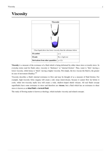
Viscosity Test of BitumenViscosity Test for BitumenViscosity test of Bitumen is carried out to determine the viscosity of bitumen specimenindirectly with the help of different viscometers available.The procedure of determining the viscosity of bitumen along with apparatus, materials, andprecautions is described below. The significance and conclusion of this test are alsodescribed.[Different types of viscometers are used to determine different kinds of viscosity as discussedbelow. The types viscosity measured are: Industrial viscosityDynamic/Absolute viscosityKinematic viscosity]Significance of the Viscosity PracticalViscosity test of the bitumen sample is one of the important tests on bitumen to beconducted before road construction.Viscosity measures the degree of fluidity of the bitumen sample. It ensures the quality ofthe bitumen used as a binder by giving a measure of fluidity at a particular temperature.If the bituminous binder used in the pavement has much lower viscosity value, then it willact as a lubricant only. It will not help in the binding of the particles, which is its primarypurpose.A highly viscous binder will restrict the flow, thus it restricts the ability of binder to spreadand fill up the voids between the aggregates during pavement construction. Also, it willrequire more efforts comparatively, and there is also a possibility of it forming aheterogeneous mix. Workability will also be affected of a highly viscous bitumen specimen.Therefore, it is essential to select a binder with appropriate viscosity so that it can form auniform coat and fill up the voids between aggregates effectively.1
Viscosity Test of BitumenDETERMINATION OF ABSOLUTE VISCOSITYAimTo determine the absolute viscosity of bitumen and cutbacks.In this practical, the absolute viscosity is determined by vacuum capillary viscometers atany stated temperature.This method is valid for materials having a viscosity range of 42-200000 poises.Important Terms related to Absolute Viscosity of BitumenAbsolute/dynamic viscosity of Newtonian liquidAbsolute Viscosity: If a tangential force equal to 1 dyne is, acting on planes of unit areaseparated by a unit distance of liquid produces tangential velocity of one unit, and then theinternal friction acting at that time is called absolute or dynamic viscosity.CGS unit of dynamic viscosity is Poise. (1 dyne 0.00001 N)Newtonian liquid: It is a liquid in which shear stress is directly proportional to the rate ofshear strain.Alternatively, it is the liquid in which the coefficient of viscosity is constant.Coefficient of viscosity: It is a ratio of shear stress to the rate of shear strain.ApparatusAny of the 3 viscometers discussed below shall be used for determining viscosity. Viscometer- Capillary type: It is made up of borosilicate glass. There are three typesof capillary type viscometers as discussed below:o Cannon Manning Vacuums Viscometer- The range of the viscosity that thisviscometer is able to measure depends on the size of the viscometer. It hastwo measuring bulbs- B and C.o Asphalt Institute Vacuum Viscometer- The range of the viscosity that thisviscometer is able to measure depends on the size of the viscometer. It hasthree measuring bulbs- B, C, and D of length 2 cm. The three bulbs aresituated on viscometer arm M. This arm is a precision bore glass capillary.o Modified Koppers Vacuum Viscometer- The range of the viscosity that thisviscometer is able to measure depends on the radii of the viscometer. It has aseparate filling tube joined to a precision bore glass capillary vacuum tubewith a borosilicate ground glass joint that has 24/40 standard taper. The glasscapillary has 2 cm long 3-bulbs separated by timing marks.2
Viscosity Test of Bitumen Bath: It is used for the immersion of viscometer. The viscometer is so immersed inthe bath that the liquid reservoir or the capillary top- whichever is the uppermost- isat least 20 mm below the top level of the bath. It has a provision that allows theviscometer and thermometer to be visible. Firm support is also present on the bathto hold the viscometer.The accuracy of viscometer should be 0.1 C over the length of viscometer or fromtwo different viscometer positions in the bath. Thermometer or Temperature indicator- Its range should be from 0 to 44 C. Itsleast count should be 0.2 C. Vacuum System- A vacuum or aspirator pump can be used as the source of vacuumin the vacuum system. All the glass joints of the vacuum system should be airtight sothat no vacuum is lost in the duration of the experiment. It should be capable ofmaintaining the vacuum within 0.05 cm.Other accessory apparatus include: Timing device like stopwatch or stop clock- It should be able to measure up to 0.5seconds.StirrerOvenMaterials Bitumen or cutback to be testedSolventDistilled waterAcetoneChromic acidPrecautionFollowing precautions should be taken while performing the viscosity of bitumen test toobtain accurate results:-Rotate the stirrer when the sample is heated in tar cupThe temperature should be strictly adhered to during the entire testLocal heating should be prevented by stirring the sampleViscometer should be cleaned periodically with chromic acid so that organic depositsare removedCalibration of thermometer should be done periodically3
Viscosity Test of BitumenProcedureSample Preparation: Take the bitumen sample in a beaker and heat it to a temperature, not more than 60 C- for tars and pitches while the temperature should not exceed 90 C- for bitumen.Allow the bitumen to melt at slightly above the softening points of the material untilit achieves a pouring consistency.Pour 20 ml of melted bitumen in a suitable container and maintain it to atemperature of 135 C with 5.5 C tolerance.Stir the bituminous material occasionally so that local heating can be avoided. Also,the entrapped air can also escape in this while.Charge the viscometer. For charging, pour the prepared sample into the cup within 2 mm of the fill line E.Place the viscometer into bath or oven after charging and maintain it to 135 5.5 C.maintain this temperature for 10 2 min to facilitate the escape of air bubbles.Testing of the Specimen: Maintain the temperature of the bath at 135 C as done previously, however,tolerance is reduced from 5.5 C to 1.0 C. Place the charged viscometer in the water bath vertically with the help of aholder. Adjust the depth of thermometer such that the uppermost timing markremains a minimum of 2 cm below the liquid surface.Connect the vacuum system to the viscometer after establishing a vacuum of 30 0.05 cm of mercury. Keep the valve of the vacuum system closed.Allow the assembly to stand in the water bath for 30 5 min.Open the valve and allow the asphalt to flow into the viscometer.Measure the time required for the leading edge of the meniscus to pass betweenthe two consecutive pairs of the timing marks in seconds. Accuracy of 0.5seconds is required. Cleaning of Viscometer After testing Remove the viscometer from the bath.Place the viscometer in the oven at 135 5.5 C in an inverted position. Allow theviscometer to stand in the oven until all the asphalt has drained off thoroughly.Rinse the viscometer several times with an appropriate solvent.Pass a slow stream of dried air through the capillary for about 2 minutes so thatthe tube is completely dry.Once in a while, clean the viscometer with chromic acid. It helps in the removalof organic deposits.4
Viscosity Test of Bitumen Rinse the instrument thoroughly with distilled water and acetone.Dry the instrument with clean air.ObservationAs the valve of the viscometer is opened, the asphalt starts flowing into the viscometer.The time taken by the leading edge of the meniscus to pass between two successive pairs oftiming marks is to be noted down in seconds.Observation Table(A sample observation table is drawn below)Test temperature Constant K DescriptionTest Trial12Efflux time (t)in secViscosity (K * t)in poiseAbsolute Viscosity of the sample Average value of 1 and 2.CalculationAbsolute viscosity of the sample is calculated and reported to the three significant figures.Following equation is used for calculating absolute viscosity:K selected calibration factor; in poise/secondt time of flow; in secondsabsolute viscosity is obtained in PoiseResultThe value of absolute viscosity is recorded to the three significant figures.The result is reported along with the test temperature as follows:Absolute viscosity at 60 C temperature ‘X’ poise5
Viscosity Test of BitumenDETERMINATION OF KINEMATIC VISCOSITYAimTo determine the kinematic viscosity of paving grade and cutback bitumen and distillationresidues of cutbacks.This method is valid for materials having a viscosity range of 30-100,000 poises.Important Terms related to Kinematic Viscosity of BitumenKinematic viscosity of Newtonian liquidKinematic Viscosity: It is the quotient of the dynamic viscosity divided by the density of theliquid under consideration, both taken at the same temperature.CGS unit of kinematic viscosity is Stoke. (1 stoke 1 cm2/s)Newtonian liquid: It is a liquid in which shear stress is directly proportional to the rate ofshear strain.Alternatively, it is the liquid in which the coefficient of viscosity of a liquid is constant.Dynamic Viscosity: If a tangential force equal to 1 dyne is acting on planes of unit areaseparated by a unit distance of liquid produces tangential velocity of one unit, then theinternal friction acting at that time is called absolute or dynamic viscosity.CGS unit of dynamic viscosity is Poise. (1 dyne 0.00001 N)Coefficient of viscosity: It is a ratio of shear stress to the rate of shear strain.Density: It is the ratio of mass per unit volume.CGS unit of density is g/cm3.ApparatusEither of the 2 viscometers discussed below shall be used for determining viscosity. Viscometer- Capillary type: It is made up of borosilicate glass. There are three typesof capillary type viscometers as discussed below:o Cannon-Fenske Viscometer (for Opaque liquids)- This is a reverse flowannealed viscometer.o BS U-Tube Modified Reverse-flow Viscometer- It is made up of borosilicateor other heat-resisting glass that does not have any visible defects. All theglass tubes of a single viscometer should be similar in composition. Theinstrument should be thoroughly annealed after finishing.6
Viscosity Test of Bitumen Bath: It is used for the immersion of viscometer. The viscometer is so immersed inthe bath that the liquid reservoir or the capillary top- whichever is the uppermost- isat least 20 mm below the top level of the bath. It has a provision that allows theviscometer and thermometer to be visible.The stirring efficiency and balance between heat losses and its input should be suchthat the temperature of viscometer is maintained within 0.1 C over the length ofviscometer. Thermometer or Temperature indicator- Its range should be from 0 to 44 C. Itsleast count should be 0.2 C.Other accessory apparatus include: Timing device like stopwatch or stop clock- It should be able to measure up to 0.5seconds.StirrerOvenMaterials Bitumen of known gradeNon-corroding Solvent, e.g. Phenol-free light tar oilPrecautionFollowing precautions should be taken while performing the viscosity of bitumen test toobtain accurate results:-Rotate the stirrer when the sample is heated in tar cupThe temperature should be strictly adhered to during the entire testTest temperature should not be lower than 20 C and it should be in the multiples of5 C-Care should be taken while using the tar cup during its cleaning- it should be cleanedgentlyCalibration of thermometer should be done periodicallyNon-corroding solvents should be used such as light tar oils free from phenolsDo not use duster for cleaning as it may lead to abrasion of the metalThe orifice at the top of the tar cup should be checked for its diameter frequentlywith a gauge-7
Viscosity Test of BitumenProcedureSample Preparation:-For Cutback bitumen and Oil distillates Open the sample container. Thoroughly mix the sample by stirring it for 30 sec.Ensure that the entrapped air is avoided.If the sample is too viscous: Take the bitumen sample in a sealed container and heatit in a bath or oven at about 60 C temperature. Pour 20 ml of melted sample in a clean and dry container of 30 ml capacity and sealthe container immediately.-For Bitumen Heat the sample to a temperature, not more than 90 C- for tars and pitches whilethe temperature should not exceed 60 C- for bitumen. Allow the bitumen to meltat slightly above the softening points of the material until it achieves a pouringconsistency.Pour 20 ml of melted bitumen in a 30 ml container.Avoid local heating and the entrapped air in the sample. Testing of the Specimen:-For Cannon-Fenske Viscometer Charge the viscometer by inverting it and applying the suction to the tube CL.Immerse the tube N in the liquid sample.Draw liquid through the N tube so that the bulb D is filled to the fill mark- G.Wipe off the excess sample from the tube N.Invert the viscometer so that it is in a normal position.Align the viscometer in the water bath so that it is vertical. The verticality can bechecked by visual inspection, which is sufficient, but for accuracy, a plumb bobcan be suspended in the tube L.Maintain a constant temperature of the water bath in which viscometer is placedto such a time that the sample reaches equilibrium in terms of temperature.For 38 C, heating is to be done for 20 min, for 100 C 25 min is required, and for135 C 30 min is required to attain temperature equilibrium.Remove the stopper in the tubes N and L consecutively after the testtemperature is obtained.Allow the sample to flow by gravity.8
Viscosity Test of Bitumen -Measure the time required for the leading edge of the meniscus to pass betweenthe two consecutive pairs of the timing marks- E to F in seconds. Accuracy of 0.1seconds is required.If this efflux time comes less than 60 sec, select a smaller capillary diameterviscometer and repeat the above procedure.For BS U-Tube Modified Reverse-flow Viscometer Adjust the BS U-tube viscometer in the bath maintained at a constanttemperature such that the L tube is kept vertical.Pour the sample through the tube N until it reaches up to the filling mark G.Allow the sample to flow freely through capillary R ensuring that the liquidremains continuous or unbroken until it reaches the lower filling mark H.When it reaches the filling mark, close the timing tube with a cork/rubberstopper in tube L so that the flow is arrested.Add more liquid, if needed, so that the level reaches slightly above the mark G.Allow the sample to attain the bath temperature. Also allow the air bubbles torise to the surface if any. Usually, this takes 20-30 min.Loosen the stopper gently and allow the sample to flow until it reaches the lowerfilling mark H. At this point, arrest the flow by pressing back the stopper.Remove the excess of the sample above the filling mark G. The sample can beremoved with the help of a special pipette. Insert it until its cork rests on the topof tube N.Apply suction gently so that air is completely drawn and the upper meniscus shallcoincide with mark G.Allow the viscometer to stand in the bath maintained at a constant temperaturefor duration such that the sample reaches temperature equilibrium.For 38 C, heating is to be done for 20 min, for 100 C 25 min is required, and for135 C 30 min is required to attain temperature equilibrium.Remove the stopper in the tubes N and L consecutively after the testtemperature is obtained.Allow the sample to flow by gravity.Measure the time required for the leading edge of the meniscus to passbetween the two consecutive pairs of the timing marks- E to F in seconds.Accuracy of 0.1 seconds is required.If this efflux time comes less than 60 sec, select a smaller capillary diameterviscometer and repeat the above procedure.9
Viscosity Test of BitumenObservationAs the valve of the viscometer is opened, the asphalt starts flowing into the viscometer.The time taken by the leading edge of the meniscus to pass between two successive pairs oftiming marks is to be noted down in seconds.Observation Table(A sample observation table is drawn below)Test temperature Constant K DescriptionTest Trial12Efflux time (t)in secViscosity (K * t)in poiseAbsolute Viscosity of the sample Average value of 1 and 2.CalculationKinematic viscosity of the sample is calculated and reported to the three significant figures.Following equation is used for calculating kinematic viscosity:C calibration constant of viscometer; in centistokes/secondt efflux time; in secondsabsolute viscosity is obtained in centistokesResultThe value of kinematic viscosity is recorded to the three significant figures.The result is reported along with the test temperature as follows:Kinematic viscosity at 60 C temperature ‘X’ cSt10
Viscosity Test of BitumenDETERMINATION OF INDUSTRIAL VISCOSITYAimTo determine the industrial viscosity of bitumen, road tar, and cutback bitumen.The industrial viscosity is measured by determining the time taken by 50-cm3 volume ofmaterial to flow from a cup through a specified orifice in standard conditions oftemperature and a specified temperature.Important Terms related to Industrial Viscosity of BitumenIndustrial viscosity: It is the property of a fluid by virtue of which it is able to resist the flowcaused by internal friction.ApparatusTar viscometer is used for determining industrial viscosity of bitumen whose parts arediscussed below: Cup: It is also known as a 10-mm cup and has a specified orifice and valve. It is madeup of hard brass tube.It has an external brass collar at the upper open end of the cylindrical cup. The collarhelps in supporting the cup in the sleeve of the water bath.While a phosphor-bronze plate, which is circular in shape is screwed into the cylinderand made conical. It has centrally located extensions made up of same material andcylindrical in shape. The plate helps in the drainage of tar after use.The extension is drilled and polished to form an orifice of 10 mm diameter. If theupper rim of the orifice is not perfectly circular, then the valve cannot be properlyseated.Internal Diameter of cup 40.0 0.5 mmExternal Diameter of cup 42.0 0.5 mmDiameter of orifice 10.000 0.025 mmLength of jet 5.000 0.025 mm[For CUTBACK BITUMEN, 4-mm cup is used instead of 10-mm. Dia of the orifice isreduced to 4.000 0.025 mm.] Water bath: It is cylindrical in shape and is made of a copper sheet. Heating of thebath is done electrically. Ensure that local heating is avoided. The water bath isplaced on three equidistant legs riveted to the wall of the bath. The legs are of suchlength that a 100-mm cylinder can be placed below the cup orifice.Diameter of water bath 160 mmDepth of water bath 105 mm11
Viscosity Test of Bitumen Valve: It is in the shape of a sphere and is made up of phosphor-bronze. It isattached to a metal rod provided with a levelling peg at upper part and hemisphereby which valve is held. It helps in closing the orifice attached to the 10-mm cup. Sleeve: It is in the form of a stout brass tube, which is bronzed into a central hole cutin the bottom of the water bath. It helps in receiving the cup so that the cup remainsin position. It has an easing sliding fit.Internal Diameter of sleeve 45 mmHeight of sleeve 105 mm Stirrer: It has 4 vertical vanes. The upper and lower portions of the stirrer can beturned in opposite directions. The stirrer is mounted on a cylinder slipping on thesleeve through an easy sliding fit. The cylinder is cut between the vanes so that heatcan be transferred from water in the bath to the tar in the cup. To prevent the waterfrom the water bath from entering the tar cup on raising the stirring system, verticalgrooves are provided on the inner surface of the cylinder. Curved shield: It is fixed at the upper edge of the cylinder. It is extended to adistance within 5 mm of the walls of the water bath. An insulating handle tofacilitate rotation of stirrer, a swivelled support for the valve, and support forthermometer are present on this curved shield. Receiver: It is a measuring cylinder with graduations at 20, 25, and 75 ml capacities.Its total capacity is 100 ml.Internal Diameter 29 mm 2-Thermometer- Two standard thermometers are required- one is placed in thewater bath and another in the cup. The range of both the thermometers should befrom 0 to 44 C. The least count is 0.2 C.Other accessory apparatus include: Timing device like stopwatch or stop clock- It should be able to measure up to 0.5seconds.Materials Bitumen sample to be testedNon-corroding Solvent, e.g. Phenol-free light tar oil12
Viscosity Test of BitumenPrecautionFollowing precautions should be taken while performing the viscosity of bitumen test toobtain accurate results:-Rotate the stirrer when the sample is heated in tar cupThe temperature should be strictly adhered to during the entire testTest temperature should not be lower than 20 C and it should be in the multiples of5 C-Care should be taken while using the tar cup during its cleaning- it should be cleanedgentlyNon-corroding solvents should be used such as light tar oils free from phenolsDo not use duster for cleaning as it may lead to abrasion of the metalThe orifice at the top of the tar cup should be checked for its diameter frequentlywith a gaugeCalibration of thermometer should be done periodically-Procedure Adjust the tar viscometer in such a way that the top of the tar cup is levelled.Heat the water bath to the specified temperature of the test and maintain it at thesame temperature throughout the test duration. Tolerance of 0.1 C is allowed.[The specified test temperatures are 35 C, 45 C, 55 C, and 65 C.] Rotate the stirrer gently at frequent intervals. Continuous rotation is preferred.Clean the orifice of the tar cup of viscometer with a suitable solvent and allow it todry completely.Heat the bitumen sample to a temperature of about 20 C above the specified testtemperature and allow it to cool. Meanwhile, rotate the stirrer continuously.Allow the sample to cool up to a temperature slightly above than the specified testtemperature.Pour the tar into the tar cup then after till the levelling peg on the valve is justimmersed. During this, the valve rod should be kept vertical.Take 20 ml of mineral oil or 1 % by weight solution of soft soap and pour it into thegraduated receiver.Place the graduated receiver under the orifice of tar cup.Place the second thermometer in the tar.Continue stirring the tar until the temperature falls within 0.1 C of the specifiedtest temperature.Then, suspend the thermometer co-axially to the cup with its bulb at the geometriccentre of the tar approximately. 13
Viscosity Test of Bitumen Allow the assembly of the apparatus to stand for 5 minutes. During this time, thethermometer reading should remain within 0.5 C of the specified test temperature. Remove the thermometer.Also, remove the excess of tar, if any quickly. This ensures that the final level is onthe centre line of the levelling peg when the valve is vertical.Suspend the valve on the valve support by lifting it.Start the stopwatch or stop-clock or any other time recording device when thereading on the cylinder is 25 ml.Note the time in seconds when the reading on the cylinder is 75 ml by stopping thestopwatch.Repeat the test for a few times with the same material and note down the results. ReportThe time at which the reading of the cylinder reaches 75 ml from 25 ml is to be noted downfor all the three samples along with the specified test temperature.Whether the sample is tested as received or dried before testing is also reported. If drying isdone, then the method of drying is also noted.If the sample is tested as received, then water is present in it. And the presence of water hasa notable effect on viscosity.Observation Table(A sample observation table is drawn below)Specified testtemperature CTime in sec1Test Number23Industrial Viscosity of the sample Average value of 1, 2 and 3.ResultThe time taken by 50 ml of tar to flow out is recorded to the nearest whole number as theviscosity of the tar sample.The time taken by the three tar samples should lie within 4 % of the mean value of thethree readings.While using CUTBACK BITUMEN, the tolerance in the difference in readings is tabulatedbelow:14
Viscosity Test of BitumenViscosity 20 sec20-40 sec 40 secRepeatability2 sec2 sec5 % of the mean15
viscometer to stand in the oven until all the asphalt has drained off thoroughly. Rinse the viscometer several times with an appropriate solvent. Pass a slow stream of dried air through the capillary for about 2 minutes so that the tube is completely dry. Once in a while, clean the viscometer with chromic acid. It helps in the removal