![01. Communication Protocols [Read-Only] - GE Grid Solutions](/img/55/commprot.jpg)
Transcription
Communication Protocols01. Communication Protocols
Table of Contents1. 7 Layer Model2. Communication Relationships3. Topologies4. Substation Implementation (UCA)5. Traditional Protocols (Modbus, IEC 870-5 T103)6. Net DDE vs. OPC7. Inter Control Center Protocol (ICCP)01. Communication Protocols
CommunicationProtocols andStandards301. Communication Protocols
Communication Protocols and StandardsPROTOCOLA set of rules for operating a communication systemAreas addressed by rules: Framing Error Control Sequence Control Transparency4 Line Control Timeout Control Startup Control Special Cases01. Communication Protocols
Communication Protocols and StandardsCommunications Model ISO 7 Layer Model Enhanced Performance Architecture Basic Network Topologies501. Communication Protocols
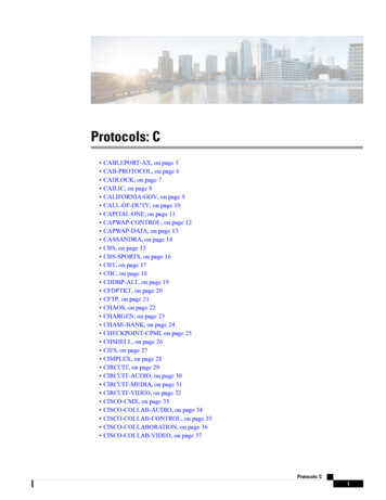
Communication Protocols and StandardsThe Open Systems InterconnectionSeven Layer Reference ModelUser AUser BUser to User CommunicationsLayer 7ApplicationLayer 6PresentationApplicationUser to User Encoded CommunicationsPresentationUser to UserLayer 5SessionLayer 4TransportLayer 3NetworkLayer 2Data LinkSessionUser to User MessagesTransportUser to User PacketsEnd to End PacketsNetworkData LinkEnd to End BitsLayer 1PhysicalPhysicalCommunication Signals601. Communication Protocols
Communication Protocols and Standards3-LAYER LAN ARCHITECTUREApplicationData LinkDNP 3.0 / Modbus / ical701. Communication Protocols
Communication Protocols and StandardsBasic Communication RelationshipsPeer to Peer Client / Server Publisher / Subscriber8Master / Slave Request / Response Response Only01. Communication Protocols
Communication Protocols and StandardsTOKEN-RING CONCEPTS901. Communication Protocols
Communication Protocols and StandardsThe Next GenerationHigh Speed Peer-to-Peer Communication1001. Communication Protocols
Communication Protocols and Standards“STAR” ArchitectureIEDIEDIED11IEDHubActive/ PassiveIEDIED01. Communication Protocols
Communication Protocols and StandardsInteroperabilityApplications and devices can exchange usefulinformation across business functions without the userhaving to engineer it.1201. Communication Protocols
Utility Communication Architecture - UCA1301. Communication Protocols
Utility Communications Architecture UCAUtility CommunicationArchitecture - UCA Arose from the need for commoncommunication across the utility enterprise Basic definition started in 1988 Defines a “suite” of protocols to address allutility communication requirements Has recently focused on SubstationCommunications1401. Communication Protocols
Utility Communications Architecture UCA7-LAYER UCA MODELMMS FTAMVTDSROSEACSEMMS1988CMIPMHS1984RTSEISO Connection-orientated PresentationISO Connection-orientated SessionISO/TCP Connection-orientated Transport0ISO/IP Connectionless NetworkES - IS RoutingLLCCSMA/ TokenTokenCDBusRing(8802/3) (8802/4) (8802/5)15X.25 Packet Layer1FDDIHDLC/LAPBV.35EIA 232-D X.214ISDNQ.931ISDNLAPDISDNInterfaces01. Communication Protocols
Utility Communications Architecture UCASubstation IntegratedProtection, Control and Data AcquisitionPhase 1, Task 2Requirements SpecificationProject/Documentation Site:Ftp.sisconet.com/epri/subdemo1601. Communication Protocols
Utility Communications Architecture UCAUtilities Participating in UCA American Electric Power (AEP) Indianapolis Power & Light Ontario Hydro - Canada Northern States Power Tampa Electric ComEd Cinergy Baltimore Gas & Electric GPU Nuon - Holland17 Enetergy TVA Duke Boston Edison Union Electric Florida Power Corp Southern California Edison Wisconsin Electric ESKOM - South Africa Natinal Grid Company - UK Polish Power Grid - Poland01. Communication Protocols
Utility Communications Architecture UCAParticipating UCA Vendors GE Power Management Basler Cooper Beckwith Tasnet SEL GE Harris RFL18 Siemens Alstom L&G Doble Dranetz / BMI /Electrotek Modicon / Square D ABB Bitronics01. Communication Protocols
Typical Substation UCA RealTime Architecture UCAUCA REAL - TIME SERVICES / GOMSFEMMS / ISO 9506A - Unit DataACSE / ISO 8650CL Presentation / ISO 9576CO Presentation / ISO 8823CL Session / ISO 9548CO Session / ISO 8327CLTP / ISO 8602TP4 / ISO 8073UTILITY ENTERPRISEWIDE AREANETWORK (WAN)RFC 1006CLNP / ISO 8473TCPES-IS / ISO 9542IPLLC / ISO 8802STANDARDROUTEREthernetGateway /Devices19PLCsRelaysSUBSTATION LANDevicesHOST01. Communication Protocols
Substation Peer-to-PeerStandard DevelopmentIEC STATUS IEC TC 57 - Working Groups 10, 11, 12 aredeveloping an IED peer to peer communicationstandard The work exists as the IEC - 61850 committeè draft Section 8.1 is based on the MMS/Ethernet UCASubstation profile UCA and IEC 61850 will be reconciled2001. Communication Protocols
Utility Communications Architecture - UCAETHERNET DescriptionCarrier Sense Multiple Access /Collision DetectionCSMA / CD .Msg @toNode 1Node 2Msg @toNode nCSMA Concept: Listen for traffic on the network.If none, proceed to transmit data.A collision occurs when two terminals transmitat the same time.2101. Communication Protocols
Utility Communications Architecture - UCAIntel Pentium IIIComputerCable under test10 Mbps Ethernet HubCapacitive CouplerKeyTek ElectricalFast TransientTest Equipment22Cable Type10BaseT (Twisted Pair)10Base2 (Coax)10BaseF (Fiber)ResultsFailFailPassInitial test configuration for 10 MbpsEthernet using Intel Pentium III based computersIntel Pentium IIIComputer01. Communication Protocols
Utility Communications Architecture - UCAMMS Service Specification Defines a set of objects that canexist within a device. Defines a set of communicationservices to access and manipulatethose objects. Defines the behavior of the deviceto those communication services.2301. Communication Protocols
Utility Communications Architecture - UCAMMS Objects Domain Program Invocation Variable Type (Variable) Semaphore (2) Operator Interface24 Event Condition Event Action Event Enrollment Journal File01. Communication Protocols
Utility Communications Architecture - UCANamed Variable Object A named MMS object representinga “real” variable Only the name is needed to access Attributes:-Object Name (scope)-MMS Deletable (boolean)-Type description-Access method (Public, tec.)-Address (Public only) Be careful about using addresses in where the address can changefrom on run-time to the next.2501. Communication Protocols
Utility Communications Architecture - UCASimple Type Definition A Simple Type definition consists of Class and Size Type Classes:BOOLEANBIT STRINGINTEGERUNSIGNED (INT)FLOAT (IEEE)REAL (ISO)VISIBLE STRINGOCTET STRINGGENERAL TIME (ISO)BINARY TIME (MMS/C)BCD Although MMS Data has the form information built-in (integer, string, boolean,etc.), only the Type Def’n has the size information needed to convert to localformat.2601. Communication Protocols
Utility Communications Architecture - UCADomain Represents a resource within theVMD. Domains are typically:-Program Memory-Recipe Memory-Data Memory, etc. Domains may be pre-named.2701. Communication Protocols
Utility Communications Architecture - UCAMMS Services Get Object Change Object Determine Attributes Create Object Delete Object2801. Communication Protocols
Utility Communications Architecture - UCADomain Services eUploadSequence rminateDownloadSequenceEach upload sequence is assigned a unique ID Number to track multiple uploads inprogress.Domain data is sent over the network in segmentsInitiateDownloadSeq creates domain-If domain exists: must delete first2901. Communication Protocols
Utility Communications Architecture - UCAUnconfirmed Services Unconfirmed services consist of only the request andindication service primitives. UnsolicitedStatus InformationReport EventNotification3001. Communication Protocols
Utility Communications Architecture - UCAProgram Invocations An execution thread consisting of one or more domains. A program invocation can be started, stopped, etc. A P.I. May be pre-named3101. Communication Protocols
Utility Communications Architecture - UCACommon Application Service Models (CASM) Generic communications services- data access- data (and exception) reporting- device control, tagging- self describing devices Detailed mapping of data objects to MMS Detailed mapping of generic services to MMS services3201. Communication Protocols
Utility Communications Architecture - UCACommon Application Service ModelMMS Services Required3301. Communication Protocols
Utility Communications Architecture - UCAGeneral Object Model forSubstation & Field Equipment(GOMSFE) Object Modeling is a technique for identifying data elementsin a device. Defines standards names, attributes, and behaviors of thedata elements Allows the re-use of names Provides the foundation for the information needed for“self-description”3401. Communication Protocols
Measurement Unit Object ModelMeasurement Unit3501. Communication Protocols
Measurement Unit Object Model3601. Communication Protocols
Data Modeling ConceptRelay DataExternally VisibleObjectsMeasurement UnitVendor InternalMemory Voltages Currents READ CONFIGURESettingsGOMSFE Vendorspecificobjects Watts Vars Settings READ WRITE Controls SOESBO OscillographyPosition OPEN CLOSEFilesGET3701. Communication Protocols
“GOOSE” Format(Generic Object Oriented Substation Event)Header DST Source local MAC address Multicast Relay Name Time of event Time until next GOOSEDNA(Dynamic NetworkAnnouncement) 32 Standard Bit Pairs, e.g.Close, Open, BFI, RI, etc.User Bits 64 “user defined” bit pairs38 Message sent as an“unconfirmed” MMSinformation report Use the EthernetMulticast Format, I.e. the MSBof the message is set to a “1” Data is sent in bit pairswhere:01 010 100 “Transition”11 Undefined01. Communication Protocols
Utility Communications Architecture - UCARelationship of CASM and GOMSFEGOMSFEUSERCASMCLIENTCASMSERVER39FIELD DEVICECONTROLLER01. Communication Protocols
Utility Communications Architecture - UCASubstation AutomationOriginal RTU ConceptTo SCADAMasterRTU Single box All signals hard wired to thesingle box Limited data availability Analog Status Alarm Complete overlay of Protection4001. Communication Protocols
Utility Communications Architecture - UCASubstation AutomationRelay Based SCADATo SCADAMasterHostComputerLine RelayXFMRRelayFeederRelay41Disk Substation Host becomesData Concentrator Data acquisition is performedby all IEDs in the substation Distributed SOE availablethrough IRIG-B time sync Oscillography data now available01. Communication Protocols
Substation AutomationArchitecture - Diagram4201. Communication Protocols
Inter Substation CommunicationsFSC(Fiber Optic System Communications) SONET Technology: 51/155 Mbps Ethernet LAN ‘Bridging’ capability Creates single Ethernet WAN Redundant channels ensure reliability4301. Communication Protocols
Architectural ConceptEnterpriseSCADA InterfaceGUI/SCADA/other applicationsFile Storage Oscillography SOE Demand DataData Server and DatabaseData Collection EnginePhysical Communication sotherOther Apps: OSC. Viewer SOE ViewerIEDs Open Architecture Commercial Hardware and Software Easy to Expand and Integrate Cost Effective Standard Packages01. Communication Protocols
DDE and OPCOverview and Comparison4501. Communication Protocols
What is DDE DDE - Dynamic DataExchange Method for exchanging databetween applicationsHMI(DDE Client)Driver(DDE Server)4601. Communication Protocols
The DDE Data ModelDDE DEItem(s)OPCItem(s)OPCItem(s)DDEItem(s)01. Communication Protocols
How DDE WorksDDE Client 1DDE Client 2DDE Client 3DDEML.DLL(DDE Management Library)DDE Server 148DDE Server 2DDE Server 301. Communication Protocols
What is OPC OPC - OLE for Process Control A Specification for softwareinteroperability in the automationindustry. Based upon Microsoft ComponentObject Model (COM)4901. Communication Protocols
The OPC Data ModelOPC m(s)OPCItem(s)OPCItem(s)OPCItem(s)01. Communication Protocols
How OPC Works51OPC Client 1OPC Client 2OPC Client 3OPC Server 1OPC Server 2OPC Server 301. Communication Protocols
DDE x OPCDDE Passes 1 value per request No time stamp No “quality” flag No underlying structure similar to OLE High resource utilization52OPC Can pass multiple values per request Time stamp standard part of theresponse “Quality” flag standard part of theresponse Based on OLE/COM Low resource utilization01. Communication Protocols
SUBSTATION NAMEADDRESS5301. Communication Protocols
UR Wizard5401. Communication Protocols
Annunciator Screen5501. Communication Protocols
Sequence of Events5601. Communication Protocols
GPS/IRIG-B Time Synchronization5701. Communication Protocols
Utility Communications Architecture - UCA5801. Communication Protocols
Utility Communications Architecture - UCATABLE G2. 4 Bit Quality Indicator CodeBINARY HEX VALUE (worst case accuracy)Fault--Clock failure, time not reliableF111110 secondsB1011A1 second1010100 milliseconds (time within 0.1 sec)9100110 milliseconds (time within 0.01 sec)810001 millisecond (time within 0.001 sec)70111100 microseconds (time within 10-4sec)601105010110 microseconds (time within 10-5sec)401001 microsecond (time within 10-6 sec)30011100 nanoseconds (time within 10-7 sec)2001010 nanoseconds (time within 10-8 sec)100011 nanosecond (time within 10-9 sec)00000Normal operation, clock locked5901. Communication Protocols
Utility Communications Architecture - UCAIRIG FORMAT ‘B’ - GENERAL1. TIME FRAME: 1.0 second.2. CODE DIGIT WEIGHTING OPTIONS: BCD, SB or both:a) Binary Coded Decimal Time-of-Year CODE WORD - 30 binary digits.(1) Seconds, minutes, hours and days. Recycles yearly.b) Straight Binary Time-of-Day CODE WORD - 17 binary digits.(1) Seconds only. Recycles each 24 hours. (86399)3. CODE WORD STRUCTURE:a) BCD: Word begins at INDEX COUNT 1. Binary-coded elements occurbetween POSITION IDENTIFIER ELEMENTS (seven for seconds,seven for minutes: six for hours: ten for days) until the CODE WORDis complete. A POSITION IDENTIFIER occurs between decimal digitsin each group to provide separation for visual resolution.b) SB: Word begins at INDEX COUNT 80. Seventeen binary-codedelements occur with a POSITION IDENTIFIER between the 9th and10th binary-coded elements.6001. Communication Protocols
Utility Communications Architecture - UCAIRIG FORMAT ‘B’ - GENERAL4. Least significant digit: occurs first.5. ELEMENT RATES AVAILABLE:a) 100 per second (basic Element rate)b) 10 per second (POSITIVE IDENTIFIER Rate)c) 1 per second (Frame Rate)616. ELEMENT IDENTIFICATION:a) ‘On-Time’ reference point for each Element is its leading edge.b) INDEX MARKER duration: 2 milliseconds(Binary zero or uncoded Element)c) CODE DIGIT duration: 5 milliseconds(Binary one)d) POSITION IDENTIFIER duration: 8 millisecondse) REFERENCE MARKER - one per second: Two consecutivePOSITION IDENTIFIERS.(The ‘On-Time’ point to which the CODE WORD refers, is theleading edge of the second POSITION IDENTIFIER.)01. Communication Protocols
Utility Communications Architecture - UCAIRIG FORMAT ‘B’ - GENERAL7. RESOLUTION: 10 milliseconds (unmodulated); 1 millisecond (modulated).8. CARRIER FREQUENCY: 1 kHz when modulated.6201. Communication Protocols
Utility Communications Architecture - UCAModified IRIG-B Code as specified by the IEEESynchrophasor Standard:DISCUSSION OF BIT ASSIGNEMENTS:By using IRIG-B with additional extensions, old and new time sourcesand time users can be easily integrated. PMU’s should be programmedto check the control bit field and use this additional information where it isprovided but rely on user entered data where it is not. Since unusedcontrol field bits are normally set to zero, where possible these newassignments are made with zero indicating a normal state. This willminimize the possibility of creating a false alarm. For example, if acontrol field was all zeroes, the time quality code would indicate theclock was locked with full accuracy which would not accidentally beinterpreted as an error condition.6301. Communication Protocols
Utility Communications Architecture - UCADISCUSSION CONT’D:Virtually every timekeeping system is run by some kind of processor.Since IRIG time code numbers arrive AFTER the on time mark, thetimekeeping system must generate the timetag based on theanticipated number rather than on what it just got. Consequently timecounts that are not in exact sequence require advance notice.Non-sequence clock counts include leap year, leap second, anddaylight savings time changes. The Leap second and Daylight savingschange bits warn of impending special clock counts, and the last twodigits of the year alert the timing system of leap year changes.6401. Communication Protocols
Traditional Protocols ModBus DNP IEC 870-5 T1036501. Communication Protocols
ModBus6601. Communication Protocols
ModBus Basic Features Master-Slave Protocol Can Address up to 254 slaves All data is accessed via resgister addresses Primarily defined on RS485 - also has been operated onEthernet Data is addressed via 2-byte registers ModBus Packet can transmit up to 120 registers per message Registers accessed must be sequential6701. Communication Protocols
ModBus Packet Format* Packet must be followed by 3.5 byte times of “dead time”Note:Each register is 2 bytesMost Significant Data bytes are sent firstLeast Significant CRC byte is sent first6801. Communication Protocols
ModBus Function Codes6901. Communication Protocols
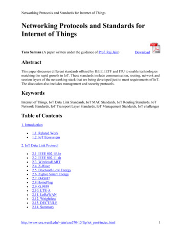
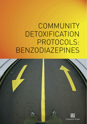
Master and Slave PacketsThe following table shows the format of the master and slavepackets. The example shows a master sevice requesting 3register values starting at address 200h from slave device 11;the slave device responds with the values 555, 0, and 100 fromregisters 200h, 201h, and 202h respectively.7001. Communication Protocols
DNPDistributed Network Protocol7101. Communication Protocols
What is DNP? Open Systems Protocol Stack Recommended by IEEE for RTU to IED messages Based on IEC 3-layer version of 7-layer OSI model Developed by Harris Controls and Released in 1993 Controlled by DNP User’s Group since Nov. 1993APPLICATIONDATA LINKPHYSICAL7201. Communication Protocols
Communication Protocol LayerStructure7301. Communication Protocols
Interoperable Basedon IEC 870-5 standards Intended for evolution to a 7-layer stack Implemented by several vendors7401. Communication Protocols
Networks Multipleoperating modes Polled Only Polled by Exception Unsolicited Report by Exception Layered protocol allows mix-and-match Allows Multiple Masters7501. Communication Protocols
DNP Features Addresscapability over 65,000 devices and 4,000,000,000 data points of each data type Broadcast Messages Configuration / File Transfer Time of Day and Date Synchronization Time-Stamped Event Data Data Priority Levels By Classes7601. Communication Protocols
DNP Design Intendedfor low-to-medium speed media 16-bit Data Link CRC’s every 16 octets Hamming Distance of 6 Optional Data Link and Applicationconfirmation7701. Communication Protocols
DNP Physical Layer Topologies Direct or Point to Point using cable, radios,modems Serial Bus or Local Area Network (LAN)using multi drop configuration Modes Asychronous, synchronous, isochronous7801. Communication Protocols
DNP Data Link Layer Accepts,performs, and controls transmissionservice for higher layers Provide for transfer of Link Service Data Units(LSDU) across the physical link Provide Frame Synchronization, Link Control,and Indications for Events Exchange of Service Data Units (SDU)between peer DNP data links7901. Communication Protocols
FT3 Frame Formatn 16 max.STARTLENGTH802 starting octets of the header (0x0564).1 octet count of USER DATA in the header and body. This countincludes the CONTROL, DESTINATION and SOURCE fields in theheader. The CRC fields are not included in the count. The minimumvalue for LENGTH is 5 indicationg only the header is present and themaximum value is 255.CONTROLFrame control octel.DESTINATION 2 octet destination address. The first octet is the LSB and the secondoctet is the MSB.SOURCE2 octet source address. The firsst octet is the LSB and the secondoctet is the MSB.CRC2 octet Cyclic Redundancy Check.USER DATA Each block following the header has 16 octets of User defined dataexcept the last block of a frame which contains 1 to 16 octets of Userdefined data as needed.01. Communication Protocols
Requests and Responses8101. Communication Protocols
DNP Transport Layer Pseudotransport layer acts as a DNP datalink layer Assembles and Disassembles frames of 255octets each8201. Communication Protocols
DNP V3.0 Application Layer MessagesControl Send Request Accept Request Confirmation Communications Error Recovery Reported to User User Layer Responsible for CorrectiveProcedure8301. Communication Protocols
DNP Application Layer MessagesTypes Requests Confirm, Read, Write, Select, Operate,Freeze, Restart, Start and StopApplications, Save Configuration, Enableand Disable Unsoliticited Messages, AssignClass, Delay Measurement Responses84 Confirm, Response, Unsoliticed Message01. Communication Protocols
Data Object Examples BinaryInputs SomeVariations: Binary Outputs 16 or 32 bit Counters Static or Event Analog Inputs \With or Without Flag Analog Outputs With or Without Time Time Frozen or non-frozen Classes of data Applications Numeric Formats8501. Communication Protocols
IEC 870-5 Afive part document detailing a “suite” ofprotocols for data communication Needs companion documents to detail aparticular implementation T103 (based on VDEW GermanStandard) DNP (partially compliant)8601. Communication Protocols
IEC 870-5 T103 “Mostly” compatible with IEC 870-5 Presently a Draft International Standard Specifies Physical Link options (RS485 & Fiber) Specifies the Data Link format (ft 1.2) Specifies the Application Layer data structures Defines standard “types” of data Allows for “Self Description” Operates in a Master / Slave mode8701. Communication Protocols
Application Service Data Unit8801. Communication Protocols
T103 Data Description Options01234567891012131489No description specifiedActual ValueDefault ValueRange (min, max, step size)ReservedPrecisionFactor% ReferenceEnumerationDimensionDescriptionPassword EntryRead OnlyWrite Only01. Communication Protocols
Inter Control Center Protocol(ICCP)9001. Communication Protocols
ICCP IntroductionAlso known as TASE.2 (Telecontrol ApplicationService Element.2)Developed initially as a part of an Electric PowerResearch Institute (EPRI) Utility CommunicationsArchitecture (UCA) initiativeSubmitted by USA to IEC TC 57 WG07Only one set of IEC standards today9101. Communication Protocols
ICCP Projects Estimated 150-200 North American utilityimplementations completed or in development 10-20 Power Pools, Independent System Operators(ISOs) Multiple International projects in various stagesof development NERC Inter-regional Security Network (ISN)–18 ICCP Nodes serving 21 Security Coordinators UCPTE9201. Communication Protocols
ICCP Projects UCPTE (European NERC) using TASE.2 for Europeaninterconnection network over TCP/IP–Germany, Netherlands, Belgium, France, Spain,Portugal, Italy,former Yugoslavia, Austria,Switzerland, others–Impact on Eastern CENTREL interconnectionnetwork Poland and others–Migration to ELCOM-90 planned Netherlands, Belgium European deregulation - TASE.2–Security and energy schedules9301. Communication Protocols
ICCP Architecture and APIsSCADADatabaseData Acq.& MgmtApplication Program InterfaceICCPMMS(Manufacturing Messaging Specification)OSI Layers 5-7OSI Layers 1- 494TCP/ IP01. Communication Protocols
ICCP Data Exchange geSchedulingInterchangeSchedulesPower PlantApps.Power pps.ICCPProviderSiteA95MMSProviderMMSObjectsMMS PDUICCPProviderMMSProviderSiteB01. Communication Protocols
ICCP Design Goals Vendor interoperability over any network Multiple transport profiles possibleLower layers transparent to ICCPRoutable over various interconnected subnetworks Maximize use of existing ISO protocol standardsin lower layersICCP confined to sublayer in layer 7 NOTProvide standard APIGuarantee portability9601. Communication Protocols
ICCP Protocol ArchitectureApplicationICCP IEC 60870-6-503/802MMSACSEPresentationISO PresentationSessionTransportNetworkISO SessionISO Transport Class 4ISO CLNP TCP IPData LinkISO 8802.2 LLC, FDDI, FR, ISDN, etc.PhysicalEthernet LAN, WAN, Point-to-Point Circuit, ATM, SDH,etc.9701. Communication Protocols
ICCP Network ConfigurationsCNP - Comm. Node ProcessorDLS - Data Link ServerSite ALegacyCCSite BNewEMSCNPDLSRouterCNPRouterRS 232CRouterFEPSite CLegacyCC98DLSSite DNewEMS01. Communication Protocols
ICCP Associations ACSE used to establish associations Established between two ICCP end nodes Typically long running QOS attribute for each association Includes priority, transit delay, throughput, residual errorrate, and protection Used by OSI Network layer At least one association per QOS value ICCP client chooses proper association9901. Communication Protocols
ICCP Client/Server ModelControlCenterUtilityAA-S1-Hi to CC BA-S2-Lo to CC BB-S1 to CC AA-S3 to PP CBLT-BB-S2toPP CBLT-CA-S4toSS DControlCenterUtilityBBLT-DC-S1 toCC BClient requester of data or serviceServer provider of data or serviceSubstationD100Note: Client “pull”, not server “push”I.e., not publisher/consumer modelPowerPlantC01. Communication Protocols
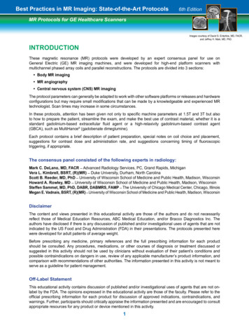
ICCP Object ModelsICCP Server ObjectsRequestResponseInformationReportControl CenterData ObjectsObject ModelsOperationsActions Association Data Value Data Set Transfer Set Account Req Device Program Event Indication Point Information Buffer Account/Schedule Protection Equip Power Plant Control PointEvent10101. Communication Protocols
ICCP TransactionsClientControl CenterRequests operationGet Data ValueGet Data SetStart TransferSelect/OperateServerControl CenterRequestServer checks accessrightsResponseResponds to clientrequestReportReports data sets asspecified in client request(action)Report10201. Communication Protocols
ICCP Implementation Each ICCP operation or action is implemented using ISO/IEC 9506 MMS MMS provides standardized services with standardized messages ICCP client operations are mapped onto MMS client services ICCP server actions are mapped onto MMS server services ICCP data objects are mapped to MMS Types10301. Communication Protocols
DNP 3.0 / Modbus / 870-5 870-5 FT3 870-5 FT1.2 RS-232 RS-485 Radio 3-LAYER LAN ARCHITECTURE Communication Protocols and Standards Modbus. 01. Communication Protocols 8 Communication Protocols and Standards Basic Communication Relationships Peer to Peer Client / Server Publisher / Subscriber Master / Slave