Transcription
Lec. Manal F. YounisFile System and DatabaseChapter OneDatabase Systems: Design, Implementation, and Management9th EditionPeter Rob & Carlos CoronelChapter 1IntroductionFile Systems and Databases1.1. The historical roots of the database:1.2. Files and file systems1.3. File system critique1.3, Database System1.3.1. Database Management Systems1.3.2. DBMS Functions1.3.3. The Database System Components (Environment)1.3.4. Types of Database Systems1.4. Data Independence1.5. Data Models1.5.1. The Hierarchical Model1.5.2.The Network Model1.5.3. The Relational Model1.1. The historical roots of the database: Files and File systemsIn the recent past, a manager of almost any small organization was able to keeptrack of necessary data by using a manual file system. Such a file system wastraditionally composed of a collection of file folders; each properly tagged and kept ina filing cabinet.Organization of the data within the file folders was determined by the data'sexpected use. Ideally, the contents of each file folder were logically related. Forexample, a file folder in a doctor's office might contain patient data, one file folder foreach patient. All the data in that file folder described only that particular patient'smedical history.As long as a data collection was relatively small and an organization's managershad few reporting requirements, the manual system served its role well as a datarepository. However, as organizations grew and as reporting requirements becamemore complex, keeping track of data in a manual file system became more difficult. Infact, finding and using data in growing collections of file folders became such a time1Database Systems: Design, Implementation, & Management, 7th Edition, Rob & Coronel
Lec. Manal F. YounisFile System and DatabaseChapter Oneconsuming and cumbersome task that it became less and less likely that such datawould ever generate useful information.Unfortunately, report generation from a manual file system can be slow andcumbersome. In fact, some business managers faced government-imposed reportingrequirements that required weeks of intensive effort each quarter, even when a welldesigned manual system was used. Consequently, the pressure built to design acomputer based system that would track data and produce required reports.1.2. File System Critique (problems):We can see the problems with the straight file-processing approach:1.2.1.File System Data Management As the number of files expands, system administration becomesdifficult, too. Each file must have its own file management system,composed of programs that allow the user to: Create the file structure, Add data to the file. Delete data from the file. Modify the data contained in thefile. List the file contents.Security features - such as effective password protection, locking outparts of files or parts of the system itself. Every user of the system shouldbe able to access only the data they are permitted to see. Multiple users: Want concurrency for faster response time. Integrity problems: Data may be required to satisfy consistency constraints.1.2.2. Structural and Data DependenceStructural Dependence: A change in any file's structure requires themodification of all programs using that file.Data Dependence: A change in any file's data characteristics requires changesin all data access programs. Significance of data dependence is that there existsa difference between the data logical format (how the human being views thedata) and the data physical format (how the computer "sees" the data).Data dependence makes file systems extremely cumbersome from aprogramming and data management point of view.2Database Systems: Design, Implementation, & Management, 7th Edition, Rob & Coronel
Lec. Manal F. YounisFile System and DatabaseChapter One1.2.3. Field Definitions and Naming Conventions. A good (flexible) recorddefinition anticipates reporting requirements by breaking up fields into theircomponents.Selecting proper field names is very important. For example, make sure that thefield names must be as descriptive as possible within restrictions. It is not obvious thatthe field name REN represents the customer's insurance renewal date. Using the fieldname CUSRENEWDATE would be better for two reasons. First, the prefixes CUS canbe used as an indicator of the field's origin, which is the CUSTOMER file. Therefore,we know that the field in question yields a CUSTOMER property. Second, theRENEW DATE portion of the field name is more descriptive of the field's contents.By using proper naming conventions, the file structure becomes self-documenting.That is, by simply looking at the field names we are able to determine which files thefields belong to and what information is likely to be contained within those fields.1.2.4. DATA REDUNDANCY:Data redundancy: Same information may be duplicated in several places.If the file system environment makes it difficult to pool data, it is likely that thesame data are stored in many different locations. For example, in Figures 1.1 and 1.2,the agent names and phone numbers occur in both the CUSTOMER and the AGENTfiles. You need only one correct copy of the agent names and phone numbers. Havingthem occur in more than one place produces data redundancy. Uncontrolled dataredundancy sets the stage for:1. Data inconsistency. All copies may not be updated properly. Data inconsistencyexists when different and conflicting versions of the same data appear in differentplaces. For example, suppose we change an agent's phone number or address in theAGENT file. If we forget to make corresponding changes in the CUSTOMER file, thefiles contain different data for the same agent. Reports yield inconsistent results,3Database Systems: Design, Implementation, & Management, 7th Edition, Rob & Coronel
Lec. Manal F. Younis File System and DatabaseChapter Onedepending on which version of the data is used. Data that display data inconsistencyare also referred to as data that lack data integrity.2. Data anomalies. The dictionary defines "anomaly" as an abnormality. Ideally, afield value change should be made only in a single place. Data redundancy, however,fosters an abnormal condition by forcing field value changes in many differentlocations. The data anomalies found in Figure 1.3 are commonly defined as:Modification anomalies. If agent Leah F. Hahn has a new phone number, that newnumber must be entered in each of the CUSTOMER file records in which Ms. Hahn'sphone number is shown. In this case, only three changes must be made. In a large filesystem, such changes might occur in hundreds or even thousands of records. Clearly,the potential for data inconsistencies is great.Insertion anomalies. To add each new customer in the CUSTOMER file, we must alsoadd the corresponding agent data. If we add several hundred new customers, we mustalso enter several hundred agent names and telephone numbers. Again, the potentialfor creating data inconsistencies is great.Deletion anomalies. If agent Alex B. Alby quits and is deleted from the payroll, all thecustomers in the CUSTOMER file become linked to a nonexistent agent. To resolvethis problem, we must modify all records in which Mr. Alby's name and phone numberappear.4Database Systems: Design, Implementation, & Management, 7th Edition, Rob & Coronel
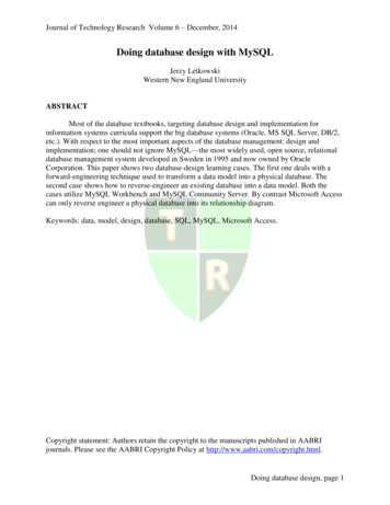
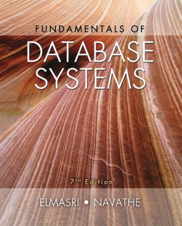
Lec. Manal F. YounisFile System and DatabaseChapter OneThese problems and others led to the development of databasemanagement systems.1.3. Database SystemThe problems inherent in file systems make using a database system verydesirable. Unlike the file system, with its many separate and unrelated files, thedatabase consists of logically related data stored in a single data repository. Therefore,the database represents a change in the way end user data are stored, accessed, andmanaged. The database's DBMS, shown in Figure 1.6, provides numerous advantagesover file system management, by making it possible to eliminate most of the filesystem's data inconsistency, data anomalies, data dependency, and structuraldependency problems.5Database Systems: Design, Implementation, & Management, 7th Edition, Rob & Coronel
Lec. Manal F. YounisFile System and DatabaseChapter OneRemember that the DBMS is just one of several crucial components of a databasesystem. Perhaps it is even appropriate to refer to the DBMS as the database system'sheart. However, just as it takes more than a heart alone to make a human being function,it takes more than a DBMS to make a database system function.Database is a collection of data or information that can be stored, sorted,organized and retrieved. Your local telephone book, your Rolodex file, and the cardcatalog at your local library are all examples of a database.Traditional databases are organized by fields, records, and files (tables). A fieldis single piece of information; a record is one complete set of fields; and a file is acollection of records. For example, a telephone book is analogous to a file. It containsa list of records, each of which consists of three fields: name, address, and telephonenumber.To access information from a database, you need a database management system(DBMS). This is a collection of programs that enables you to enter, organize, and selectdata in a database.1.3.1. A database management system (DBMS)DBMS is a collection of programs that manages the database structure andcontrols access to I the data stored in the database. The DBMS makes it possible toshare the data in the database among multiple applications or users. Because data arethe crucial (H ) raw material from which information is derived, there are many goodreasons why DBMSs are important in our information-basedThe goal of a DBMS is to provide an environment that is both convenient andefficient to use in: Retrieving information from the database. Storing information into the database.6Database Systems: Design, Implementation, & Management, 7th Edition, Rob & Coronel
Lec. Manal F. YounisFile System and DatabaseChapter OneFigure 1.4 illustrates the concept that the DBMS stands between the database and theuser(s). In effect, the DBMS serves as the intermediary between the user and thedatabase by translating user requests into the complex code required to fulfill thoserequests. The DBMS hides much of the database's internal complexity from theapplication programs that use the database. The application program might be writtenby a programmer, using a programming language such as COBOL, Microsoft Access,and Oracle or it might be created through a DBMS utility program.1.3.2. DBMS FunctionsA DBMS perform several important functions that guarantee the integrity andconsistency of the data in the database. Most of these functions are transparent to endusers. These functions include:1- Data Dictionary Management: The DBMS requires that definitions of the dataelements and their relationships (metadata: data about data) be stored in a datadictionary.2- Data Storage Management: The DBMS creates the complex structures required fordata storage.data structures that are required to store the data.3- Data Transformation and Presentation: The DBMS transforms entered data toconform to the data structures that are required to store the data.4- Security Management: The DBMS creates a security system that enforces usersecurity and data privacy within the database. Security rules determine which users canaccess the database, which data item each user may access, and which data operationsthe user may perform.5- Multi-User Access Control: The DBMS creates the complex structures that allowmulti-user access to the data. In order to provide data integrity and data consistency,7Database Systems: Design, Implementation, & Management, 7th Edition, Rob & Coronel
Lec. Manal F. YounisFile System and DatabaseChapter Onethe DBMS uses sophisticated algorithms to ensure that multiple users can access thedatabase concurrently and still guarantee the integrity of the database.6- Backup and Recovery Management: The DBMS provides backup and data recoveryprocedures to ensure data safety and integrity.7- Data Integrity Management: The DBMS promotes and enforces integrity rules toeliminate data integrity problems, thus minimizing data redundancy and maximizingdata consistency.8- Database Access Languages (DDL and DML) and Application ProgrammingInterfaces: The DBMS provides data access via a query language. A query languageis a nonprocedural language; which contains two components: a Data Definitionlanguage (DDL) and a Data Manipulation Language (DML).9- Database Communication Interfaces: Current-generation DBMSs provide specialcommunications routines designed to allow the database to accept end user requestswithin a computer network environment.1.3.3. The Database System Environment: Hardware: Computer, Peripherals. Software: refers to the collection of programs that are used by the computerswithin the database system. The three types of software are: Operating systems software: manages all hardware components and makes itpossible for all other software to run on the computers. Such as DOS, OS/2, UNIX,XP windows. DBMS software: manages the database within the database system. Such asOracle, Access. Applications programs and utilities software: are used to access andmanipulate the data in the DBMS and to manage the computer environment inwhich the data access and manipulation take place. People (User): Systems administrators: oversee the database system's generaloperations.Database administrators (DBAs): is a person having central control over data andprograms accessing that data.Database designers: design the database structureSystems analysts and programmers: design and implement the applicationprograms.End users: are the people who use the applications programs to run the organization'sdaily operations Procedures: Instructions and rules that govern the design and use of the databasesystem. Data: Collection of facts stored in the database.8Database Systems: Design, Implementation, & Management, 7th Edition, Rob & Coronel
Lec. Manal F. Younis File System and DatabaseChapter One1.3.4. Types of Database Systems: Can be classified by user:– Single-user: Supports only one user at a time– Desktop: Single-user database running on a personal computer– Multi-user: Supports multiple users at the same time– Workgroup: Multi-user database that supports a small group of users ora single department– Enterprise: Multi-user database that supports a large group of users or anentire organizationCan be classified by location:– Centralized: Supports data located at a single site– Distributed: Supports data distributed across several sitesThe DBMS, on which the database system is based, can be classified according on thenumber of users, the database site location(s)1- The number of users determines whether the DBMS is classified as single-useror multi-user. A single-user DBMS supports only one user at a time. In other9Database Systems: Design, Implementation, & Management, 7th Edition, Rob & Coronel
Lec. Manal F. YounisFile System and DatabaseChapter Onewords, if user A is using the database, users B and C must wait until user A hascompleted database work. In contrast, a multi-user DBMS supports multipleusers at the same time. If the multi-user database supports a relatively smallnumber of users or a specific department within an organization, it is called aworkgroup database.The DBMS, on which the database system is based, can be classified according on thenumber of users, the database site location(s).1. The number of users determines whether the DBMS is classified as single-user ormulti-user. A single-user DBMS supports only one user at a time. In other words, ifuser A is using the database, users B and C must wait until user A has completeddatabase work. In contrast, a multi-user DBMS supports multiple users at the sametime. If the multi-user database supports a relatively small number of users or a specificdepartment within an organization, it is called a workgroup database.2. The database site location might also be used to classify the DBMS, for example, aDBMS system that supports a database located at a single site is called a centralizedDBMS. A DBMS that supports a database distributed across several different sites iscalled a distributed DBMS.1.4. Data Independence1. The ability to modify a scheme definition in one level without affecting a schemedefinition in a higher level is called data independence.2. There are two kinds: Physical data independence:1- The ability to modify the physical scheme without causing applicationprograms to be rewritten.2- Modifications at this level are usually to improve performance. Logical data independence:1-The ability to modify the conceptual scheme without causingapplication programs to be rewritten2- Usually done when logical structure of database is altered.3- Logical data independence is more difficult to achieve than physical dataindependency since application programs are usually heavily dependent on thelogical structure of the data access. The concept of data independence is similarin many respects to the concept of abstract data types in modern programminglanguages.10Database Systems: Design, Implementation, & Management, 7th Edition, Rob & Coronel
Lec. Manal F. YounisFile System and DatabaseChapter One1.5. Database ModelsA database model is a collection of logical constructs used to represent thedata structure and the data relationships found within the database. Databasemodels can be grouped into two categories: conceptual models andimplementation models. The conceptual model focuses on the logical nature of the datarepresentation. Therefore, the conceptual model is concerned with what isrepresented in the database, rather than with how it is represented.Conceptual models include the entity relationship (E-R) model. The implementation model places the emphasis on how the data arerepresented in the database or on how the data structures are implementedto represent what is modeled. Implementation models include thehierarchical database model, the network database model, the relationaldatabase model, and the object-oriented database model. Conceptualmodels use three types of relationships to describe associations among data:one-to-many, many-to many, and one-to-one. Database designers usuallyuse the shorthand notations 1:M, M:N, and 1:1 for them, respectively.(Although the M:N notation is a standard label for the many-to-manyrelationship, the label M:M may also be used.) The following examplesillustrate the distinctions among the three:1.One-to-many relationship. Each record in a table is related to many recordsin another table for example, a painter paints many different paintings, buteach one of them is painted by only that painter. Thus the painter (the "one")is related to the paintings (the "many"). Therefore, database designers labelthe relationship "PAINTER paints PAINTING" as 1:M. Similarly, acustomer account (the "one") might contain many invoices, but thoseinvoices (the "many") are related to only a single customer account. The"CUSTOMER generates INVOICE" relationship would also be labeled1:M.2. Many-to-many relationship. Many records in a table are related to manyrecords in another table for example, Student can take many courses, andeach course can be taken by many students, thus yielding the M:Nrelationship label for the relationship expressed by "STUDENT takesCOURSE."11Database Systems: Design, Implementation, & Management, 7th Edition, Rob & Coronel
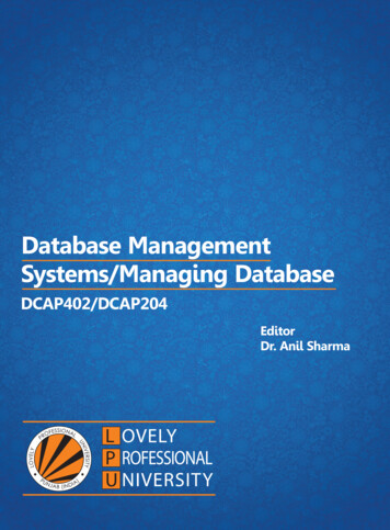
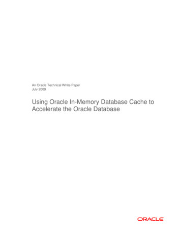
Lec. Manal F. YounisFile System and DatabaseChapter OneOne-to-one relationship. Each record in a table is related to one record inanother table. Dean of the college is related with the college in 1:1 relationship eachcollege has one Dean and each Dean is managed one college.3.1.5.1. The Hierarchical Database ModelBasic StructureThe user perceives the hierarchical database as a hierarchy of segments. A segment isthe equivalent of a file system's record type. In other words, the hierarchical databaseis a collection of records that is logically organized to conform to the upside-down tree(hierarchical) structure shown in Figure 1.8.Within the hierarchy, the top layer (the root) is perceived as the parent of the segmentdirectly beneath it. For example, in Figure 1.8, the root segment is the parent of thelevel 1 segment, which, in turn, is the parent of the level 2 segments, and so on. Inturn, the segments below other segments are the children of the segment above them.In short, Each parent can have many children. Each child has only one parent.Given this hierarchical structure, it is easy to trace both the database's componentsand the 1 :M relationships among them.Keep in mind that the tree structure shown in Figure 1.8 cannot be duplicated on thecomputer's storage media. The computer does not the logical tree structure as humanbeings do. Instead, the tree is defined by a path that traces the parent segments to thechild segments, beginning from the left.12Database Systems: Design, Implementation, & Management, 7th Edition, Rob & Coronel
Lec. Manal F. YounisFile System and DatabaseChapter OneThis ordered sequencing of segments tracing the hierarchical structure is called thehierarchical path.For example, the hierarchical path to the segment labeled "Part D" in Figure 1.8 canbe traced this way: Final assembly — Component A —* Assembly A— Part A— Part B — Component B — Component C — Assembly B — Part C — Part DNote:1.2.Organization of records is as a collection of trees, rather than arbitrary graphs.Each segment is represented record.1.5.2. The Network Database ModelThe network database model was created to represent complex datarelationships more effectively than the hierarchical model could, to improve databaseperformance, and to impose database standard specifications for three crucialdatabase components:1. The network schema, the conceptual organization of the entire database as viewedby the database administrator. The schema includes a definition of the database name,the record type for each record, and the components that make up those records. "Theoverall design of the database”.13Database Systems: Design, Implementation, & Management, 7th Edition, Rob & Coronel
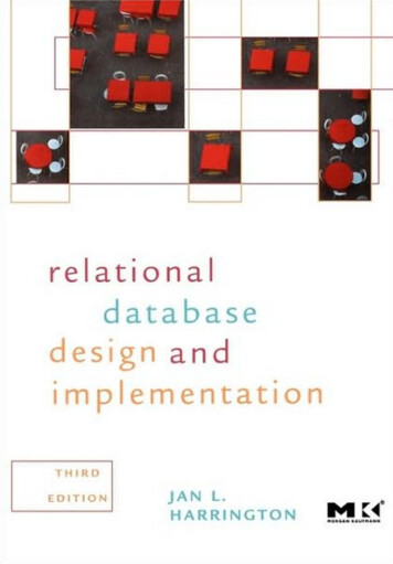
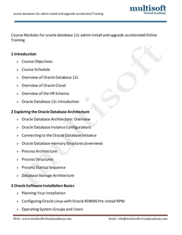
Lec. Manal F. YounisFile System and DatabaseChapter OneThe subschema, which defines the portion of the database "seen" by theapplication programs that actually produce the desired information from the datacontained within the database. The existence of the network database model wascreated to represent complex data relationships more effectively than the hierarchicalmodel could, to improve database performance, and to impose database standardspecifications for three crucial database components:2. The network schema, the conceptual organization of the entire database as thedatabase administrator. The schema includes a definition of the database name, therecord type for each record, and the components that make up those records. "Theoverall design of the databaseBasic StructureAs in the hierarchical model, the user perceives the network database as acollection of records in 1:M relationships. However, quite unlike the hierarchicalmodel, the network model allows a record to have more than one parent. Therefore,the commonly encountered relationships depicted in Figure 1.9 can be handled easilyby the network database model.Using network database terminology, a relationship is called a set. Each set iscomposed of at least two record types: an owner record that is equivalent to thehierarchical model's parent, and a member record that is equivalent to the hierarchicalmodel's child. The difference between the hierarchical model and the network modelis that the latter might include a condition in which a record can appear (as a member)in more than one set. In other words, a member may have several owners. A setrepresents a 1:M relationship between the owner and the member. An example of sucha relationship is depicted in Figure 1.10.The network database model in Figure 1.10 illustrates transactions that are based on aseries of one-to- many relationships:1. A SALESREP might have written many INVOICE tickets, but each INVOICE ticketwas written by a single SALESREP. Therefore, there is a 1:M relationship betweenSALESREP and INVOICE.2. A CUSTOMER might have made purchases on different occasions. Each time ashopping trip is made, a new INVOICE ticket is written; that is, a CUSTOMER mayhave generated many INVOICE tickets over time, but each INVOICE belongs to onlya single CUSTOMER. Therefore, there is a 1:M relationship between CUSTOMERand INVOICE.14Database Systems: Design, Implementation, & Management, 7th Edition, Rob & Coronel
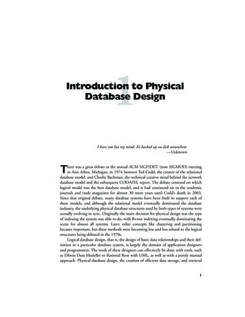
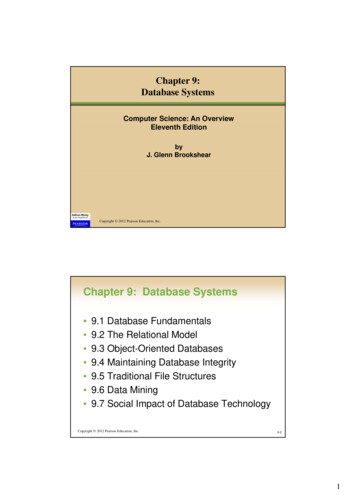
Lec. Manal F. YounisFile System and DatabaseChapter One3. Each product purchased is listed on one of the invoice's lines. Because a customermay buy more than one product at a time—for example, you can buy a screwdriver, abox of screws, and a can of paint during your visit to a store each invoice can have oneor more lines on it. But each INVLINE occurring on a particular INVOICE "belongs"to that invoice. Therefore, there is a 1:M relationship between INVOICE and INVLINE.Each invoice line references a single product. But, because a store can sell manyscrewdrivers during any period of time, a product can appear on many different invoicelines. Therefore, there is a 1:M relationship between PRODUCT and INV LINE.A customer may make many payments over a period of time. But only one customermakes each payment. Therefore, there is a 1:M relationship between CUSTOMER andPAYMENT.Note1. Data are repeated by collections of records.2. Relationships among data are represented by links "pointer".3. Organization is an arbitrary graph.1.5.3 The Relational Database Model Basic Structure-The relational database model is implemented through a very sophisticated relationaldatabase management system (RDBMS). The RDBMS performs the same basicfunctions provided by the hierarchical and network DB MS systems plus a host ofother functions that make the relational database model easier to understand and toimplement.-The data and relationships are represented by a collection of tables.-The relational model does not use pointers or links, but relates records by the valuesthey contain (P.K., F.K)-Each table is a matrix consisting of a series of row/column intersections. Tables, alsocalled relations, are related to each other by sharing a common entity characteristic.For example, the CUSTOMER table in Figure 1.11 might contain a sales agent'snumber that is also contained in the AGENT table.15Database Systems: Design, Implementation, & Management, 7th Edition, Rob & Coronel
Lec. Manal F. YounisFile System and DatabaseChapter One-Although the tables are completely independent of one another, we can e asilyconnect the data between tables. The relational model thus provides a minimum levelof controlled redundancy to eliminate most of the redundancies commonly found infile systems.-The relationship type (1:1, 1:M, or M:N) is often shown in a relational schema, anexample of which is depicted in Figure 1.12. The relational schema shows theconnecting fields (in this case, AGENTCODE) and the relationship type. MicrosoftAccess, the database software application used to generate Figure 1.12, employs the symbol to indicate the "many" side. In this example, the CUSTOMER represents the"many" side, because an AGENT can have many CUSTOMERS. The AGENTrepresents the "1" side, because each CUSTOMER has only one AGENT.16Database Systems: Design, Implementation, & Management, 7th Edition, Rob & Coronel
Lec. Manal F. Younis File System and Database Chapter One 6 Database Systems: Design, Implementation, & Management, 7th Edition, Rob & Coronel Remember that the DBMS is just one of several crucial components of a database system. Perhaps it is even appropriate to refer to the DBMS as the database system's heart.