Transcription
FabShops: Intro to 3D PrintingSketchUp Make TutorialBy Adrian YaoSketchUp Make is a free 3D computer assisted drawing/modeling (CAD/CAM) tool that is open for anyone todownload and use; it is the free version of SketchUp Pro—the paid version. While the capabilities of SketchUp Make arelimited, an advantage that it supports software extensions written in the Ruby programming language. These extensionsare free and available on Ruby script forums, and thus make SketchUp a dynamic, customizable, and constantly evolvingtool for anyone.In this tutorial, you will make an I-beam structure that has several features. This should teach you the most basictools available and relevant to you in SketchUp and 3D printing. If you would like to learn more, there are a ton of tutorialvideos online that are helpful.Basic Tools:IconToolDescription(shortcut key)Rectangle(r)Circle(c)PolygonArc(a)Push/Pullor aser(e)Orbit(o)Draw rectangles on a plane. Start by clicking any point to be a starting corner and the diagonalof the rectangle will follow the cursor. Click again to release point. To draw exact dimensions,start by clicking on a start point, then type in “x , y” units for dimensions and press “enter.” Holddown “shift” to draw perfect square.Draw circles on a plane. Start by clicking any point to be the center of the circle and the radiuswill follow the cursor. Click again to release point. To draw exact dimensions, start by clicking ona start point, then type in “r” units for radius and press enter. (Note this is not an ellipse tool buta circle tool)Draw regular polygons on a plane. Start by clicking any point to be the center of the polygon.Then type in the number of sides you wish for the polygon to have. The radius to the apex of thepolygon will then follow your cursor. Then follow the same instructions to use the Circle tool.Draw arcs on a plane. Start by clicking to designate the two end points of the line segment, thenthe amount of bend will follow your cursor. Click again to release.Convert 2D surfaces into 3D shapes by “pushing” and “pulling” surfaces in a directionperpendicular to the planes. Start by clicking a surface. The extrusion will follow your cursor.Click to release and create solid. To push/pull exact dimensions, click a surface and take yourcursor in the direction you would like to extrude, then type in “d” units.Move objects by clicking and objects will follow your cursor. To move objects to exact places,you can type in “d” units after clicking object and taking the cursor to the direction you would liketo move. Alternatively, you can use the cursor to snap objects onto points of other objects.Rotate objects. Start by clicking the center of rotation and a click again to establish a zerodegree line. The object will then rotate about the center as a second angle line follows yourcursor. Click again to release. To rotate exact dimensions, type in “r” in degrees and press“enter.”Scale objects. Place your cursor over an object and drag “handles” will appear. Click and scaleobjects as necessary. Hold down “shift” to preserve proportions. Hold down “control” or “option”on mac to scale about the center of object. To scale objects to exact ratios, start by clicking ahandle, and entering in “r” for a ratio, then press “enter.”Use to draw guidelines to help with modeling.To draw an infinite construction line:Start by clicking an arbitrary point on a line (either from axes or from object) and an infiniteconstruction line parallel to the line you clicked will follow your cursor. Click to release line orenter exact distance away from line.To draw a guide segment and point:Start by clicking an endpoint or corner and a guide line segment will follow your cursor. Clickto release or enter exact distance away from point to draw guide segment. A guide point willthen appear.Use to erase lines, guidelines, or objects. Click and drag over lines to erase and they will bedeleted upon release.Use to orbit around object you are creating. Use only if you do not have a mouse. Otherwise,click the scroll wheel on the mouse to orbit.
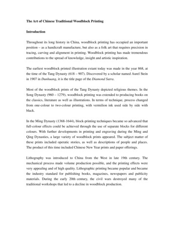
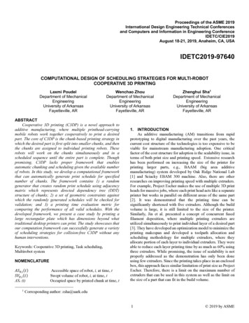
Part Tutorial:Starting1.Open SketchUp Make and go toPreferences Template “ProductDesign and Woodworking – Millimeters”2.Close current workspace and reopen new file. Workspace should have an aqua-tintedbackground3.Start by drawing a rectangle of 70mm,70mm and extrude it up by 5mm.Creating Through-Holes1.Use the tape measure tool to provide intersection points where through holes will be located.Draw infinite construction lines 15mm from each side onto the surface of the block.2.Then click the circle tool and use the intersection points of the construction lines as the centers ofthe through-hole circles. Draw four circles of 2mm radius at each intersection.
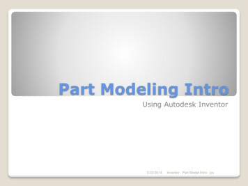
3.Cut the circles out of the block byextruding them into the block. Use thebase of the block as a reference pointfor your cursor.4Erase construction lines as necessary. Voila! You have your through-holes!Creating Countersunk Holes1.Use the tape measure tool to draw a construction line across the middle of the block. Use thetape measure tool again to create an intersection point where the countersunk holes will be.These should be 7.5mm way from one edge.2.Draw two circles of 3.5mm radius atthose intersection points3.Cut the holes halfway into the block using the push/pull tool. Use a construction line if necessaryor use the cursor to snap to the midpoint of the height dimension.4.Create a construction line 3.5mm away from the center line5.Highlight only the circle edge of the holeon the surface of the block. Then usethe scale tool and hold down “shift” and“control” (“option” on Mac) whiledragging the side handle toward thenew construction line. This shouldexpand the circle edge about its originalcenter and create a cone-likecountersunk structure.
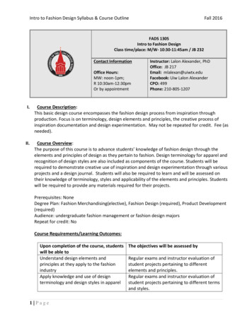
6.Once you have the two countersunk cones created, you can then extrude the rest of the circlethrough the block.7.Again, erase any construction lines asnecessary and you have just createdcountersunk holes!Creating the “T” Flange1.Use the tape measure tool to draw a5mm rectangle across the middle of theblock.2.Extrude the rectangle up by 70mm tocreate the “T” flange and erase anynecessary guidelines.
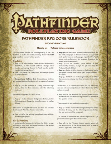
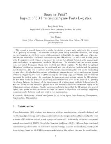
Filleting and Rounding Corners1.First off we will round the corners of the base block. To do that, we will use the arc tool. Drawconstruction lines 4mm away from each edge on the base block.2.With the arc tool using the constructionlines as a guide, draw an arc tangent tothe edge of the base block. Notice howthe arc color will change at significantradii. Once the arc color has changedand a label indicates that it is “Tangentto Edge,” click to release.Repeat this with all four corners.3.Extrude the unwanted corners away toround off corners.4.To fillet the flange, we will again draw an arc, but this time, we will draw an arc in free space.5.Draw construction lines 4mm away fromeach edge of the flange. Takeadvantage of the colored axes to drawperpendicular to each edge.
6.After drawing the construction lines, wecan again draw an arc, but this time infree space.7.Extrude these new surfaces and eraseany unwanted lines.Mirroring the Flange1.Now that we have half of the symmetrical structure built, we can mirror it about itself and join thetwo structures.2.First triple-click or highlight the entire object and create a group by pressing “Control g”(“command g” on Mac).3.Then, using the move tool, we will movethe object aside. However, while doingso, press “control” (“option” on Mac)and this will create a duplicate object.
4.Since the object is symmetrical across two planes, we can either use the rotate tool to rotate onepart upside down, or use the scale tool to mirror one part.5.To rotate the part, use the rotate tool. Make sure the rotate tool is on the correct plane. In thiscase, it should be on the green plane.6.To mirror the part, use the scale tooland drag the center handle on face intothe negative region. Make sure it snapsto the ratio of -1.00.7.Now we can use the move tool to movethe reflected part onto the original part.Using the move tool, click a corner onthe surface of the “T” to be butt againstthe corresponding location on theoriginal part.
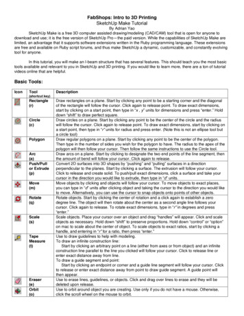
8.Once this is done, explode both groupsand erase the dividing lines. Thiseffectively joins the two parts into one.Creating an Array of Holes1.On one face of the midsection of the IBeam, create construction lines 15mmaway from the sides and 20mm awayfrom the edges of the fillet.2.Create the shape seen on the right. Theradius of curvature is 5mm, and thecenters are 20mm apart
3.To create an array, we will use the move tool, coupled with the “control” (“option” on Mac) keyand a simple keystroke.4.Highlight the boundary of the shape youjust created and create a duplicate to bemoved to the intersection point to itsright.5.Then right after clicking the mouse torelease the object, type in “/2.” Whatthis does is it creates two copies of theobject you just duplicated and itpositions them evenly spaced acrossthe distance the object was moved.6.To make a 2D array, we will highlight allthree shapes that were just created andmove and duplicate them vertically in asimilar fashion to create an array of 9shapes.Finally, extrude all shapes to createholes and erase all necessary lines.
Creating 3D Text1.Find the 3D Text tool under Tools 3DText. A dialogue window will pop up.Type in what you want, and specify thefont.2.Once you press “place,” an object appears that is the word that you just typed in 3D. Move andscale the label and place it on your model. Use guidelines if you would like an exact placement.3.Double click into the group to edit the3D shapes. You can adjust the height ofthe extrusion here.Finishing Up1.2.Since the 3D text is in itself a solid part that is grouped, it is important to combine both parts tocreate one single solid part that is 3D printable.First, highlight everything except the 3Dtext, and group them together. To checkthat it is indeed a solid part without anyerrors, right click it and choose “entityinfo.” This should bring up a window.Notice the Volume. If your “entity info”window does not have a Volume, thenyour part is not a complete solid. Youwill need to find any extraneous lines orany incomplete surfaces to fix this.
3.Once you are sure your part is in fact asolid, go to View Tool Palettes SolidTools. This should bring up a tool box.4.Click the top left option (the union tool) and highlight both the I-Beam and the 3D text. This willunify both groups into one solid. To check that it is a solid, check the entity info and check for thevolume.Voila! You have your part complete!Tips on making 3D Printable/Feasible files: Keep in mind that if you have overhangs in your parts, the quality may not be as good.Most 3D printers have a maximum overhang angle of 45º that is printable without the need for supportstructures.Unless you have a dual extruder head that can print support structures in a different material, the finalfinish may not be as good.Think about infill for parts that need to bear loadYou can use acetone to smooth out parts printed with ABS plastic, and THF to smooth out parts printedwith PLA.To export a SketchUp file into a 3D printable .stl file, download and install the Ruby extension from theSketchUp Extension Warehouse: -stl
SketchUp Make is a free 3D computer assisted drawing/modeling (CAD/CAM) tool that is open for anyone to download and use; it is the free version of SketchUp Pro—the paid version. While the capabilities of SketchUp Make are limited, an advantage that it supports software extensions written in the Ruby programming language. These extensions