Transcription
FACE CONSULTANTS LTDASTM : E1155 MAmerican Society of Testing Materials(USA)F Number SurveysFurther explanatory information
F NUMBER SURVEYSMethod statement to survey a floor’s surface regularity, in accordance with the’American Society for Testing and Materials’EquipmentF Speed Reader and Android PhoneChalkLong Tape MeasureShort Tape MeasureMethodThe ASTM recommends that 2 basic properties of the floor’s surface regularityshould be checked:1.Flatness-FF2.Levelness-FLAn FF and FL number will be specified for each local area and the overall area.Example: Overall FF50/FL40, Local FF45/FL35.A higher number indicates a better flatness or levelness.The above properties should be tested, by random sampling along straight lines, inthe following manner:The F Speed Reader is simply run down sections of the floor at walking speed andthe F numbers for each of the test runs are generated by the F Speed readersoftware. The specification requires the minimum total length of the survey runs (Lin metres) is greater than the Total floor Area (A) divided by 10.Example: A floor area (A) or ‘Test Section’ of 30m x 30m 900m2Total length of survey lines L 900 / 10 90 metresHalf of the total survey length is to be run in one direction and the other half at rightangles. Placing equal numbers of lines of equal aggregate length both parallel toand perpendicular to the longest test section boundary.
Example: 3 x 15m runs parallel to longest boundary and 3 x 15m runs at rightangles to longest boundary.Organisation of Survey Area1. Test Surface – On any one building level, the entire floor area constitutesthe test surface.2. Test Section – A test section consists of any sub division of the test surface.3. No test section shall measure less than 2.4 metres on a side nor comprisean area less than 12 m2.4. No test section boundary shall cross a construction joint.a)Divide the test surface into test sections. Give each test section anidentification number and record location of all test section boundaries on thesurvey plan. See example ‘Organisation of Survey Area’ plan.b)Determine the number, length and location of all sample measurement lines(survey runs) to be used in each test section.No survey run should be less than 3.3 metres.No part of any survey run shall be within 0.6 metres of any test section boundary,wall, penetration or similar discontinuity.c)The area is set out by marking the start and stop positions of each surveyrun. This can be done from building features such as columns, construction joints,walls etc. Give each survey run a different identification number. See example‘Organisation of Survey Runs’ plan. The start and stop positions of each survey runshould be recorded on the survey plan.Survey runs parallel with the longest test boundary should be of equal length tothose at 90 degrees to the longest test boundary (alternatively lines may beorientated at 45 degrees to the longest boundary).
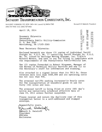
Survey ProcedureThe F Speed Reader is simply walked along the floor between the start and stoppoints and the data collected digitally. At the end of a survey run the data isdownloaded to a phone and then the next run can start. When the whole of thefloor is surveyed the phone is then connected to a laptop or PC and all the surveydata downloaded to the F Speed Reader program. At the touch of a button thedata is analysed, the overall and local F numbers are calculated and a results tableproduced.F Speed Reader
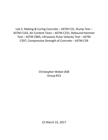
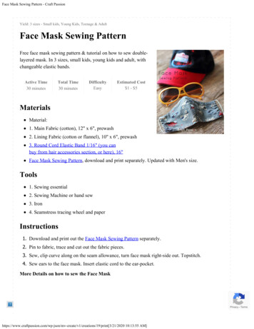
ResultsOn the page overleaf is an example of a summary sheet of results produced by theF Speed Reader.The job details include: Job name, job number, location, survey date, surveyorsinitials, area tested (m2) and specified tolerances (overall and local)The surface results are then tabulated as followsOverall FF and FL achievedFF and FL by sectionEach test section then has the survey runs listed with there individual FF and FLnumbers.Understanding F NumbersF numbers is a statistical method for the evaluation of the surface regularity of afloor. Along each of the straight lines measured, a curvature profile is seebelow.
F-Numbers ReportJob NameFC/XX/XXXXLocationDD/MM/YYYYJD900.0Job Name:Job Number:Location:Date:Surveyor:Total Area:Specified TolerancesFFFLOverallMinimum Local30303030Surface ResultsFFFLOverall19.718.0Combined .717.218.0Section1Minimum Local FFMinimum Local FLRunRun 1Run 2Run 3Run 43030Achieved FF Achieved FL FF20.317.318.220.518.917.2FL[16.6 ‐ 24.0][14.1 ‐ 20.4][14.8 ‐ 21.5][16.7 ‐ 24.2]19.814.319.417.2[15.9 ‐ 23.7][11.5 ‐ 17.1][15.5 ‐ 23.2][13.8 ‐ 20.7][17.3 ‐ 20.5][15.6 ‐ 0Section2Minimum Local FFMinimum Local FLRunRun 5Run 6Run 7Run 8Run 9Run 103030Achieved FF Achieved FL FF23.520.725.116.320.724.7[17.4 ‐ 29.6][15.3 ‐ 26.0][18.6 ‐ 31.5][12.1 ‐ 20.5][15.4 ‐ 26.1][18.3 ‐ 31.1]21.119.5FL14.818.730.728.326.914.5[10.3 ‐ 19.4][13.0 ‐ 24.4][21.3 ‐ 40.0][19.7 ‐ 37.0][18.7 ‐ 35.1][10.1 ‐ 18.9][19.0 ‐ 23.2][17.1 ‐ 4.024.024.0
In the same manner, the elevation between points separated by three meters arecalculated, z in mm, as indicators of levelness – see below.The average and standard deviation of the values q ( q y S q ) and z ( z y S Z ) arethen calculated and the F numbers of a measurement line are defined as:115.84FF 3sq q314.67FL 3sz z
In order to obtain the F numbers of a section having two or more measurementlines, a combined F number is calculated by using the following equation.Fj k Fj Fkrj rkrk Fj2 rj Fk2With rj and rk as the number of measurements obtained in lines j y k, and Fj k thevalue of the combined F number of both lines.By proceeding in an iterative manner with all the lines of a section, the F numbersof the section are obtained.Finally, the F numbers of the surface are calculated by weight averaging the Fnumbers of the sections according to the corresponding area of each section.The distribution of the lines should be chosen so that they are evenly arrangedacross the entire test section; lines may be orientated at 45 degrees however FaceConsultants usually place the lines perpendicular and parallel to the longestboundary having an equal total length in each direction.F number values usually vary between 10 and 100, a higher number indicatesbetter flatness or levelness.Further queries on these specifications or on any other floor flatness issue can be answered bycalling Face Consultants Limited direct on:TEL: 01484 6000 90FAX: 01484 6000 95
The ASTM recommends that 2 basic properties of the floor’s surface regularity should be checked:- 1. Flatness - FF 2. Levelness - FL An FF and FL number will be specified for each local area and the overall area. Example: Overall FF50/FL40, Local FF45/FL35. A higher number indicates a better flatness or levelness. The above properties should be tested, by random sampling along straight lines .