Transcription
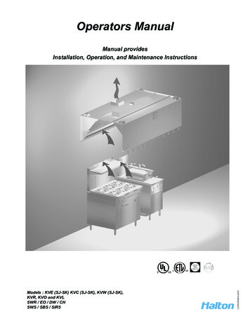
Operators ManualModels : KVE (SJ-SK) KVC (SJ-SK), KVW (SJ-SK),KVR, KVO and KVLSWR / EO / DW / CHSWS / SBS / SIR5CJOM/2009/rev2/ENManual providesInstallation, Operation, and Maintenance Instructions
1GENERAL DESCRIPTIONAll Halton Capture Jet hood systems provide solutions for a variety of commercial foodservice ventilation applicationsover virtually any cooking process. Halton’s Capture Jet technology gives the most efficient system on the market.To achieve the optimum performance from your hood system (s) please use the following guidelines provided withinthe pages of this Installation, Operation, and Maintenance Manual.In addition to this information our offices or local representatives are available at any time to provide additionaltechnical support for products, applications, installation, commissioning or in any aspect that you may have.RECOMMENDATIONUpon receipt of the Halton hood (s), inspect unit (s) immediately for any shipping damage and notify carrier immediatelyif damage is found. Halton will not accept responsibility for any shipping damage. All systems are thoroughly inspectedbefore leaving our factories, however Halton will assist in filing a claim if needed.GENERAL INSTALLATIONIt is the responsibility of the installing contractor to see that the system installation is completed in accordance with theproject plans and specifications and that it meets all specific requirements of local code officials. The local authorityhaving jurisdiction could over rule some of the installation details written in this manual. The installation shall be inaccordance with NFPA-96. All electrical systems shall be installed following local and national codes.The owner and/or operator should be instructed in the proper operation, care and maintenance of the system.If questions or complications should arise during the installation of the Halton hood (s) that cannot be solved using theinstructions provided please contact the Halton office at 1-800-442-5866, or (1-800-4-HALTON).Note: There are no instructions contained within this manual for installation or maintenance of fan packages.**See appropriate manufacturers manual for detailed instructions.EXHAUST AIRFLOWSBecause the listed exhaust airflows rates were established under controlled laboratory conditions, please seesubmittal drawings or contact the manufacturer for exhaust air flow rates.CJOM/2009/rev2/EN
2INSTALLATION INSTRUCTIONS1.Inspect the crating carefully. If there are signs of damage, call the freight carrier before uncrating the units.Carefully uncrate the units. Check all local codes prior to installation, special requirements may be necessarydepending on local building material construction.** Important note ** Do not leave unit (s) exposed to extreme temperatures for an extended periodof time, this may cause the protective PVC coating around the unit (s) to become very difficult toremove.2.Position the hood near the actual installation site. In case of multiple hoods, check the engineered set ofdrawings for locations. Pay close attention to collar sizes and fire protection layouts, matching the hoodsystems to the correct location shown on the drawings provided.**Check item numbers on crates / hoods vs. drawing item numbers.3.Once the hood is carefully removed from the shipping crate and set in position, the unit is now ready forinstallation. If Halton Company has supplied a backsplash assembly, then the splash assembly shouldbe installed first, for installation procedures. (See pg. 4)4.Hang the hood using ½” threaded rods by attaching the rods to the hood through the hanger brackets that arewelded to the top of the hood. Use of turnbuckles will make final adjustment easier. Standard hanging heightfor canopy hoods ranges from 78” min. to 84” max. above the finished floor (per local codes havingjurisdiction). **Noted in installation instructions - (see pg. 6).**All typical installations for Capture Jet series hoods shown on pages 15-22.5.If Closure Panels are supplied by Halton (see pg. 8) for details on the installation.6.For multiple hoods end to end, or back to back (see pg. 7) for Installation of Splice Strips and U-Channels.7.For hoods equipped with a supply fire damper, it is very important to make sure that the fire damper is set in anopen position before connecting the supply duct.8.Electrical circuits should be connected according to standard switch panel wiring diagram, shown on (pg. 11).For Halton Capture Jet series hoods, a typical wiring diagram is shown on (pg. 12).9.Grease filters and grease cups must be installed in place before start-up.10.Install 100 watt maximum light bulbs in standard incandescent lights or fluorescent bulbs (36” L or 48”L) influorescent lights. **Note: Halton does not provide bulbs.11.Protect the hood from damage under normal job site conditions, until all work is complete and system is readyto be put into operation.CJOM/2009/rev2/ENFor units with exhaust fire dampers, (see pg. 9), or supply fire dampers, (see pg. 10) for installationdetails.
3OPERATION OF SYSTEM1.After installation is complete, it will be necessary to check and balance the airflows. On the Capture Jet line of hoods, Halton supplies T.A.B. (testing and balancing) ports for measuring the pressure drop. Theseports are located on the inside of the canopy on each plenum. (Exhaust and Capture Jet ).For details on their use (see pg. 13). For hoods without ports, use of standard practices (duct traverse /average velocity / etc) for measuring airflows will be required.**It is very important that the fan for the Capture Jet air be balanced according to specifications.See the job specific information for required airflows. Adjustments to the Capture Jet fan can be madewith the speed controller supplied with the fan. This speed controller will be mounted inside or on top of thehood, or mounted in an electrical enclosure.Information regarding the fan and speed controller (see pg. 12).Each Halton Capture Jet hood system will have a “KSA” filter remover (model KFR). The “KFR” will bepackaged separately, inside the hood, the box will be labeled “Attn: Kitchen Mgr. “ Model KFR instructions on(pg. 14). The KFR will assist in removal of the filters for assembly and cleaning.3.After the exhaust and supply airflows have been properly balanced, a final inspection should be made toensure proper system operation.2.HOOD MAINTENANCE1.Clean the hood canopy inside and out as needed with mild soap and water. Never use harsh or abrasivecleaners on Stainless Steel or Painted surfaces, making sure to wipe clean all interior and exteriorsurfaces of the hood including the light fixtures.** Never clean the hood canopy when any of the surfaces are hot.2.Clean the filters and grease cup(s) daily, first washing by hand, and then placing them into a dishwasher orby steam cleaning.** Handle the Grease filters carefully **CJOM/2009/rev2/EN
1” Insulated Backsplash Assembly4Screw through top offlange to wall.*( screw head will notinterfere with hood)Screw backsplashto wall or attach withadhesive.Flat Sheet Backsplash AssemblyCJOM/2009/rev2/ENHalton canopy hoodsshould be installedfrom 78” min.- 84”max. above thefinished floor.
Typical Hood Installation Details5*Optional Unistrut / TurnBuckle DetailHanger Bracket / TurnBuckle Detail Welded to top of hood.18 ga. material AllThread (By Others)Hang the hood using 1/2” threaded rods by attaching the rods to the hood through the hanger brackets (as shown)which are welded to the top of the hood, using the turnbuckles will make final adjustments easier. Hanging height ofCanopy hoods should be per local building codes, verify with “Authority Having Jurisdiction” for hanging heightin your project location.CJOM/2009/rev2/ENStandard hanging height is 78” minimum to 84” maximum above the finished floor.
RecommendedExhaust DuctInstallation Details6ExhaustDuct Options AvailableSupply DuctExhaust Ductper codeSupplyDuctScrews or Rivets are not to interfere with the operation of thefire damper (if equipped).CJOM/2009/rev2/ENSupply Duct may be attached to supply collar with sheetmetal screws or pop rivets and sealed with duct tape.
7Splice Strip / U-Channel AssembliesHoods shown back to backFig. 1BBSplice StripAU-ChannelInstallation Notes:U-Channel:For hood models that are placed back to back (as shown in Fig. 1):Slide the U-Channel A up over the back of the hood systems, and securewith sheet metal screws.For hood models that are placed end to end (as shown in Fig. 2):Pry apart the U-Channel at one end and slide over the end panels, fasteningin place, fitting around the perimeter of the hood systems.ASplice Strip:For hoods placed back to back: Slide Splice Strip B over bottom of hoodsfirst, then over top, secure by welding together.For hoods placed end to end: Slide over bottom front edge first then overtop, secure by welding together, or as an option using screws for models withsupply plenum.BSplice StripHoods shown end to endFig. 2U-ChannelBCJOM/2009/rev2/ENAA
Closure Panel Assembly8DECBCABInstallation Notes:1) Panels “A” and “B” are to set on top of the hood perimeter.*Vertical flange at the bottom of closure panel and verticalflange on top of hood should line up.2) Hammer clips “C” over the two vertical flanges.3) Attach panels “B” to wall using appropriate hardware “D”.4) Slide front panel “A” into place.D5) Attach panels “A” and “B” together using hardware “E”*(Hardware not provided by Halton)BBACCCJOM/2009/rev2/ENE
9Exhaust Fire Damper AssemblyOptional in Models : SWR / SWS / SIR5 / DW / KVE / KVC / KVW1. Remove grease filters.2. Uncoil Stainless Steel cable attached at clip (A)3. Thread end of cable from eyebolt at clip (A) going through eyebolt at clip (B), then thread through eyeboltat clip (C).4. Hold fire damper in maximum open position to attach “S” hooks at point (D), close “S” hooks to secure.5. For final adjustment of fire damper, tighten eye bolts at clips (A), (B) and (C) so that cable has no slack,and assure maximum open position is obtained.** (Access to fire protection exhaust duct nozzle to be provided by others)The collar is supportedby a 1/2” flange locatedon the inside perimeterof the damper.Eye boltSecure “S” hook to damperas shown.Fusable Link**Located in below detailas (D).Clip (B)DClip (C)Clip (A)CJOM/2009/rev2/EN
Supply Fire Damper Assembly10Optional in Models: SWR / SWS / SIR51. It is important that damper is set in open position before installing supply duct.2. Hold damper in maximum open position, fasten “S” hook at end of stainless steel cable ontothe hole located in the middle of the supply fire damper flange, closing ends of the “S” hook tosecure.3. On final adjustment of the supply fire damper, tighten cable using eyebolts to assure maximumopen position.The collar is supportedby a 1/2” flange locatedon the inside perimeterof the damper.Secure “S” hook to damperas shown.Eye boltFusible Link**Located in below detailmarked (D).CJOM/2009/rev2/END
11Standard Switch Panel Wiring*(For Hoods not equipped with Capture Jet )- #5---- ---- ---- ---- ----- By Electrician------------------------------ By HaltonWires Numbered as shown in junction box.CJOM/2009/rev2/EN
Capture Jet Fan Installation12This style is standard for Model KVLIntegrated Capture Jet fan(Standard)(Optional)KSA FilterCapture Jet FanT.A.B. PortsSpeedControllerTop of HoodFront ofHoodCapture Jet Plenum5 AMP Speed Controller wired ontop of hood or located in the ControlPanelModels KVE, KVC, KVR and KVW areequipped with an Integrated Capture Jet fanpackage, as shown above.Typical Wiring of Capture Jet FanCJOM/2009/rev2/ENw/ Halton supplied Switch Panel
13T.A.B. - Testing and Balancing PortsExhaust T.A.B. Readings vs. AirflowT.A.B. Port Readings0.35Hood ModelKVE/KVCKVWKVRKVLDesign T.A.B. (inches WC)0.250.250.250.290.30This example shows how to determine the correct T.A.B.port reading for the exhaust hoods.In this example, a design airflow of 1700 cfm is selectedfrom the Airflow axis, and a vertical line is drawn up tothe T.A.B. pressure curve for this hood.A horizontal line is then drawn for the T.A.B. pressurecurve to the T.A.B. reading axis on the left-hand side ofthe chart and the corresponding pressure is read off thechart as 0.19 inches of Water Column.T.A.B. Reading (In. WC)Capture Jet 0Airflow (cfm)Measured PressureThe Capture Jet and exhaust air flows are easily andaccurately determined by measuring the pressuredifference from the T.A.B. (Testing and Balancing)ports mounted in each plenum. The correspondingair flows can be read from the diagram provided.To properly measure T.A.B. port readings use amagnehelic gauge or digital manometer and forexhaust plenum reading hookup hose from negativeconnection on instrument to T.A.B. Port on exhaustplenum. Leave positive connection on instrumentopen to atmosphere.Closeup viewof T.A.B. Port**** It is very important the cooking equipment is in operation to create a thermal plume, prior to the air balancer, to be ableto use the T.A.B. ports.CJOM/2009/rev2/EN****For accurate results, the balance contractor should receive a copy of the job specific hood plans with the design T.A.B.readings from the hood supplier prior to balancing.
KSA Filter Removalwith Model KFR14S.S. CouplingS.S. Pipe16 ga. S.S. BracketTo assemble the KFR filter remover:Screw together stainless steel pipe, coupling, and bracket and tighten all joints.(as shown in above picture)Filter Installation and RemovalTo remove filter:Insert bracket into the inside KSA filter slots, and liftupward until filter slides out of plenum.To install filter:*** It is very Important to lock top lip of filter in placein installation as shown in reference drawing.To removefilterTo installfilterCJOM/2009/rev2/ENPlace filter on KFR (filter removal tool) bracket, raise filterinto place inside exhaust plenum. Slide upward untiltop lip of filter is locked into place and bottom lip of filterslides in place inside the exhaust plenum.
15Round / Oval Style Hood SystemsModel KVR & KVO3D Plan view of round KVR3D Plan view of oval KVRModel KVR Round and Oval hoods can be shipped in pieces for field assembly. If pieces areshipped loose, parts will be marked for easy assembly, and an Operation and Installation, andMaintenance manual will be provided.45º minfilter angleCross section of KVR24”minimumheightCJOM/2009/rev2/EN
Model EOTypical Installation16UL listed upblast fan for restaurantcooking appliances16 ga. duct all weldedper codeFilters78”-84” A.F.F.Standard**(Verify with Authority in projectlocation for min. hanging height)Model DWExhaust AirIncandescentLightsKSA FiltersCJOM/2009/rev2/ENIncandescentLights
17Model CHTypical Installation78”-84” A.F.F.Standard**(Verify with Authority in projectlocation for hanging heightrequirements).CH w/ 2 baffles - optionBafflesPerimeter Gutter**Available with and without bafflesS.S. DrainCJOM/2009/rev2/EN
Model KVETypical Installation18UL listed upblast fan for restaurantcooking appliances40 “ min.16 ga. duct work allwelded per code**Incandescent orFluorescent lightingavailable.Optional Capture Jet intake location**(standard top mountedCapture Jet intake)KSA Filters78”-84” A.F.F.StandardCapture JetAirflowCJOM/2009/rev2/EN**(Verify with Authorityin project location formin. hanging height)
Model KVCTypical Installation19120” min.40” min.Filtered MUAunit on theroof16 ga. duct work allwelded per codeStainlessSteel KSAfiltersMake-up airflowCapture Jet air78” - 84” A.F.F.78” Std.**(Verify with Authorityin project location formin. hanging height)CJOM/2009/rev2/EN
KVL Typical Installation20UL listed upblast fanfor restaurant cookingappliances40” min.16 ga. duct work allwelded per codeCapture Jet airCapture Jet fan58” -64” A.F.F.**Note: on Model KVL the Capture Jet fan is mounted on top of hood .CJOM/2009/rev2/ENStainlessSteel KSAfilters**(Verify with Authority inproject location for min.hanging height)
Model KVWTypical Installation21See page (22) for supply optionsUL listed upblast fan for restaurantcooking appliances40” min.Integrated Capture Jet location78” - 84” A.F.F.(78” Std.)**(Verify with Authority in projectlocation for min. hanging height)Side view of typical installExhaust AirIncandescentlightsIntegratedCapture Jet fanT.A.B. PortsS.S. KSAFiltersCJOM/2009/rev2/EN
Model KVW Typical InstallationExhaust Air22(W/ 1 Perf Plenum)Supply AirIncandescentlightingIntegratedCapture Jet fanT.A.B. PortsS.S. Perf(Low Velocity)KSA filtersCapture Jet AirExhaust Air(W / 2 Perf Plenum)Supply AirSupply AirIncandescentlightingIntegratedCaptur Jet fanT.A.B. PortsS.S. Perf(Low Velocity)KSA FiltersCJOM/2009/rev2/ENCapture Jet Air
WARRANTY ACTIVATION FORMThis form must be completed and returned to Halton in order for your warranty to be valid.Job & Location Information:Job Name:Street Name:City:State:Equipment Start-Up Date:Zip Code:Product Serial Numbers:Contact Information:Contact Name:Title:Chef, Kitchen Mgr/Facilitly Mgr/Property Mgr/ etc.Facility Management Company Name (if applicable):Email:Phone Number:Cell Number:Submit by EmailPlease use the "Submit by Email" button to submit this form electronically or:Fax completed form to:Halton CompanyAttention: Service DepartmentFax: (270) ompany.com
HALTON LIMITED WARRANTYHalton (“Manufacturer”). Warrants only to its direct purchasers and to no others, that all productsmanufactured by the Manufacturer shall be free from defect in materials and workmanship for a periodof twelve (12) months from the date of the original installation and start-up or eighteen (18) monthsfrom date of shipment, whichever occurs first. All products sold but not manufactured by Manufacturerwill be warranted for a period of twelve (12) months from date of shipment. (Halton’s Warranty Cardmust be completely filled out and returned to Halton within 3 weeks after the equipment start-update for your warranty to be valid *IMPORTANT NOTE: “IF” this form is returned within the specifiedtimeframe, Halton will extend your standard warranty by 120 days.)For products manufactured by the Manufacturer we agree to pay any reasonable labor costs necessaryto repair or replace, at Manufacturers option, defective parts or materials for a period of twelve (12)months from date of original installation and start-up or eighteen (18) months from date of shipment,whichever occurs first. All labor costs subject hereto shall be performed during standard work hours atstraight-time rates.For products sold but not manufactured by the Manufacturer we agree to pay any reasonable labor costsnecessary to repair or replace, at Manufacturers option, defective parts or materials for a period of (90)days from date of original installation and start-up or (12) months from date of shipment, whicheveroccurs first. All labor costs subject hereto shall be performed during standard work hours at straighttime rates.Purchaser shall pay incurred premium labor charge, including overtime, weekends and holidays.Travel time, service charges, miscellaneous tools, material charges, and labor charges resulting frominaccessibility of equipment will not be paid by Manufacturer.This LIMITED WARRANTY SHALL APPLY ONLY to products that have been installed and maintainedin accordance with the installation and Care Instruction Manuals. Purchaser shall be solely responsiblefor adhering to the instructions and procedures set forth in the said instruction manuals.This LIMITED WARRANTY SHALL NOT BE APPLICABLE to any damage or defect resulting from fire,flood, freezing or any Act of God, abuse, misuse, accident, neglect or failure to adhere to all instructionsset forth in the installation and Care Instruction Manuals. Furthermore, this limited warranty shall notapply to any product that has been altered, unless such alteration has been approved in writing by aduly authorized representative of the manufacturer. In no event shall the manufacturer be liable for anyloss, expense, personal injury or consequential damage, of any kind or character, as may result from adefect in material, and/or workmanship, however caused.EXCEPT AS IS EXPRESSLY SET FORTH IN THIS LIMITED WARRANTY, MANUFACTURER MAKESNO WARRANTY OF MARKETABILITY FOR FITNESS OR ANY PARTICULAR PURPOSE. NEITHERDOES MANUFACTURER MAKE ANY WARRANTY, EXPRESSED OR IMPLIED, WITH RESPECT TOPRODUCTS SOLD BY MANUFACTURER OR AS TO THE USE THEREOF.Halton Company101 Industrial Drive, Scottsville, KY 42164, USAPhone 270 237 5600 Fax 270 237 5700Website: www.haltoncompany.comHalton Indoor Climate Systems, Ltd.1021 Brevik Place, Mississauga, ON L4W 3R7, CanadaPhone 905 624 0301 Fax 905 624 0301CJOM/2009/rev2/ENContinuous product improvement is a Halton policy, therefore specifications and design are subject to change without notice.
10. Install 100 watt maximum light bulbs in standard incandescent lights or fluorescent bulbs (36" L or 48"L) in fluorescent lights. **Note: Halton does not provide bulbs. 11. Protect the hood from damage under normal job site conditions, until all work is complete and system is ready to be put into operation. 2