Transcription
QMP 7.1 D/FChannabasaveshwara Institute of Technology(Affiliated to VTU, Belgaum & Approved by AICTE, New Delh(NAAC Accredited & ISO 9001:2015 Certified Institution)NH 206 (B.H. Road), Gubbi, Tumkur – 572 216. Karnataka.Department of Mechanical EngineeringLAB MANUAL(2020-21)MATERIAL TESTING LABORATORY(18MEL37A/47A)III/IV SemesterName:U.S.N:Batch:Section:
QMP 7.1 D/FChannabasaveshwara Institute of Technology(Affiliated to VTU, Belgaum & Approved by AICTE, New Delh(NAAC Accredited & ISO 9001:2015 Certified Institution)NH 206 (B.H. Road), Gubbi, Tumkur – 572 216. Karnataka.Department of Mechanical EngineeringMATERIAL TESTING LABORATORY2020-21Prepared By:Reviewed By:Mr. Sriharsha S RAssistant ProfessorDept. of Mechanical EngineeringC I T, Gubbi, Tumkur.Dr. Siddeshkumar N GAssociate ProfessorDept. of Mechanical EngineeringC I T, Gubbi, Tumkur.Approved By:Dr. Giridhar S KulkarniHead of the DepartmentDept. of Mechanical EngineeringC I T, Gubbi, Tumkur.
QMP 7.1 D/FChannabasaveshwara Institute of Technology(Affiliated to VTU, Belgaum & Approved by AICTE, New Delhi)(NAAC Accredited & ISO 9001:2015 Certified Institution)NH 206 (B.H. Road), Gubbi, Tumkur – 572 216. Karnataka.CONTENTSSL.NOSubjectPage No01Vision and Mission of college and department02Syllabus03Objectives and Outcomes of the labiv04Safety measuresv05Material Testing Lab Layoutvi06List of Experimentsvii07Lab Lesson PlanExp.Noiii-iiiviii-ixTitle of the ExperimentPage No1Tensile test on Universal Testing Machine.022Compression test on Universal Testing Machine.103Shear test on Universal Testing Machine.164Bending Test on metallic and non-metallic specimens.185Torsion Test.226Izod Impact Test307Charpy Impact Test348Rockwell Hardness test389Brinell Hardness test.4210Vickers’s Hardness test4611To study the wear characteristics of ferrous,Non-ferrous and composite material for different parameters.50121314Non-destructive testinga) Magnetic crack detectionb) Dye penetration testing.Preparation of specimen for Metallographic examination of differentEngineering materials.Heat treatment: Annealing, normalizing, hardening and tempering ofsteel.Viva Questions52566065-74
Channabasaveshwara Institute of Technology(Affiliated to VTU, Belgaum & Approved by AICTE, New Delhi)(NAAC Accredited & ISO 9001:2015 Certified Institution)NH 206 (B.H. Road), Gubbi, Tumkur – 572 216. Karnataka.College VisionTo create centres of excellence in education and to serve the society by enhancing thequality of life through value based professional leadership.College MissionTo provide high quality technical and professionally relevant education in a diverselearning environment.1.2.3.4.5.6.To provide the values that prepare students to lead their lives with personalintegrity, professional ethics and civic responsibility in a global society.To prepare the next generation of skilled professionals to successfully competein the diverse global market.To promote a campus environment that welcomes and honors women and menof all races, creeds and cultures, values and intellectual curiosity, pursuit ofknowledge and academic integrity and freedom.To offer a wide variety of off-campus education and training programmes toindividuals and groups.To stimulate collaborative efforts with industry, universities, government andprofessional societies.To facilitate public understanding of technical issues and achieve excellence inthe operations of the institute.Vision of the DepartmentTo create state of the art learning environment to nurture the learning, blending humanvalues, academic professionalism and research process in the field of mechanicalengineering for the betterment of society.Mission of the DepartmentThe mission of the department is to:1. Provide requisite foundation to our students in Mechanical Engineering.2. Provide cutting edge laboratory resources to bridge the gap between theoreticaland practical concepts.3. Provide exposure to various mechanical industries through periodic industrialvisits.4. Enhance our students skill set and to make them industry ready by systematicskill development program.i
B. E. MECHANICAL ENGINEERINGChoice Based Credit System (CBCS) and Outcome Based Education (OBE)SEMESTER – III/IVMATERIAL TESTING LABCourse CodeCIE Marks4018MEL37A/47ATeaching Hours/Week (L:T:P)0:2:2SEE Marks60Credits02Exam Hours03Course Learning Objectives: To learn the concept of the preparation of samples to perform characterization such as microstructure,volume fraction of phases and grain size. To understand mechanical behaviour of various engineering materials by conducting standard tests. To learn material failure modes and the different loads causing failure. To learn the concepts of improving the mechanical properties of materials by different methods likeheat treatment, surface treatment etc.Sl.ExperimentsNo.PART A1Preparation of specimen for Metallographic examination of different engineering materials.To report microstructures of plain carbon steel, tool steel, gray C.I, SG iron, Brass, Bronze &composites.234567891011Heat treatment: Annealing, normalizing, hardening and tempering of steel.Metallographic specimens of heat treated components to be supplied and students should reportmicrostructures of furnace cooled, water cooled, air cooled, tempered steel.Students should be able to distinguish the phase changes in a heat treated specimen compared tountreated specimen.Brinell, Rockwell and Vickers’s Hardness tests on untreated and heat treated specimens.To study the defects of Cast and Welded components using Non-destructive tests like:a) Ultrasonic flaw detectionb) Magnetic crack detectionc) Dye penetration testing.PART BTensile, shear and compression tests of steel, aluminum and cast iron specimens using Universal TestingMachineTorsion Test on steel bar.Bending Test on steel and wood specimens.Izod and Charpy Tests on Mild steel and C.I Specimen.To study the wear characteristics of ferrous and non-ferrous materials under different parameters.Tensile, shear and compression tests of steel, aluminum and cast iron specimens using Universal TestingMachineFatigue Test (demonstration only).Course Outcomes: At the end of the course, the student will be able to:CO1: Understand the mechanical properties of materials by Performing experiments.CO2: Analyse the material failure and the failure inducing agent/s.CO3: Apply the knowledge of testing methods in related areas to improve structure/ behavior of materials.ii
Conduct of Practical Examination:1. All laboratory experiments are to be included for practical examination.2. Breakup of marks and the instructions printed on the cover page of answer script to be strictly adhered bythe examiners.3. Students can pick one experiment from the questions lot prepared by the examiners.4.Changeexperiment is allowed only once and 15% Marks allotted to the procedure part to be made zero.SchemeofofExamination:ONE question from part -A:30 MarksONE question from part -B:50 MarksViva -Voice:20 MarksTotal: 100 Marksiii
Channabasaveshwara Institute of Technology(Affiliated to VTU, Belgaum & Approved by AICTE, New Delhi)(NAAC Accredited & ISO 9001:2015 Certified Institution)NH 206 (B.H. Road), Gubbi, Tumkur – 572 216. Karnataka.COURSE OBJECTIVES: To learn the concept of the preparation of samples to perform characterization such asmicrostructure, volume fraction of phases and grain size. To understand mechanical behavior of various engineering materials by conductingstandard tests. To learn material failure modes and the different loads causing failure. To learn the concepts of improving the mechanical properties of materials by differentmethods like heat treatment, surface treatment etc.COURSE OUTCOMES:At the end of the course, the student will be able to: Understand the mechanical properties of materials by performing experiments. Analyze the material failure and the failure inducing agent/s. Apply the knowledge of testing methods in related areas to improve structure/behaviour of materials.iv
Channabasaveshwara Institute of Technology(Affiliated to VTU, Belgaum & Approved by AICTE, New Delhi)(NAAC Accredited & ISO 9001:2015 Certified Institution)NH 206 (B.H. Road), Gubbi, Tumkur – 572 216. Karnataka.Department of Mechanical EngineeringLABORATORY SAFETY PRECAUTIONS1. Do not play with electricity.2. Carelessness not only destroys the valuable equipment in the lab but also costs yourlife.3. Mere conductivity of the experiment without a clear knowledge of the theory is of novalue.4. Before you turn on a switch, think of the consequences.5. Do not start the experiment until the experimental setup is verified.INSTRUCTIONS TO THE CANDIDATES1. Students should come with thorough preparation for the experiment to be conducted.2. Students will not be permitted to attend the laboratory unless they bring the practicalrecord fully completed in all respects pertaining to the experiment conducted in theprevious class.3. Experiment should be started only after the staff-in-charge has checked theexperimental setup.4. All the calculations should be made in the observation book. Specimen calculations forone set of readings have to be shown in the practical record.5. Wherever graphs are to be drawn, A-4 size graphs only should be used and the sameshould be firmly attached to the practical record.6. Practical record should be neatly maintained.7. They should obtain the signature of the staff-in-charge in the observation book aftercompleting each experiment.8. Theory regarding each experiment should be written in the practical record beforeprocedure in your own words.v
MECHANICALDEPARTMENT OF MECHANICAL ENGINEERING
Channabasaveshwara Institute of Technology(Affiliated to VTU, Belgaum & Approved by AICTE, New Delhi)(NAAC Accredited & ISO 9001:2015 Certified Institution)NH 206 (B.H. Road), Gubbi, Tumkur – 572 216. Karnataka.DEPARTMENT OF MECHANICAL ENGINEERINGMATERIALS TESTING LABLIST OF EXPERIMENTSPART-A1. Preparation of specimen for Metallographic examination of different engineeringmaterials. To report microstructures of plain carbon steel, tool steel, gray C.I, SG iron,Brass, Bronze & composites.2. Heat treatment: Annealing, normalizing, hardening and tempering of steel.3. Metallographic specimens of heat treated components to be supplied and studentsshould report microstructures of furnace cooled, water cooled, air cooled, temperedsteel Students should be able to distinguish the phase changes in a heat treatedspecimen compared to untreated specimen.4. Brinell, Rockwell and Vickers’s Hardness tests on untreated and heat treatedspecimens.5. To study the defects of Cast and Welded components using Non-destructive tests like:a. Ultrasonic flaw detectionb. Magnetic crack detectionc. Dye penetration testing.PART-B123456Tensile, shear and compression tests of steel, aluminum and cast iron specimens usingUniversal Testing MachineTorsion Test on steel bar.Bending Test on steel and wood specimens.Izod and Charpy Tests on Mild steel and C.I Specimen.To study the wear characteristics of ferrous and non-ferrous materials under differentparameters.Fatigue Test (demonstration only).vii
Channabasaveshwara Institute of Technology(Affiliated to VTU, Belgaum & Approved by AICTE, New Delhi)(NAAC Accredited & ISO 9001:2015 Certified Institution)NH 206 (B.H. Road), Gubbi, Tumkur – 572 216. Karnataka.DEPARTMENT OF MECHANICAL ENGINEERINGLECTURE PLANFACULTY NAME:SEM: III /IVSUB: Material Testing LabSUB.CODE:18MEL37A/47ASl.No.DateLessonPlan No.Name of the ExperimentBatch :1LP.12LP.23LP.3 To study the behavior of the given material undertensile load and to determine the following. Percentage elongation in length. Percentage reduction in area. Working stress or permissible stress or safe stress. Young’s modulus. Yield stress. Ultimate stress or Maximum tensile stress. Breaking stress or Failure stress. Tensile test on Universal Testing Machine. To study the behavior of the given material underCompressive load and to determine the following. Modulus of elasticity. Maximum Compressive strength or ultimate stress Percentage Decrease in length. Percentage Increase in area. Compression test on Universal Testing Machine. To determine the shear strength of the givenstandard specimen under single and double shear. Shear test on Universal Testing Machine.4LP.4 To conduct bending test for the given specimenand to determine the following. Modulus of elasticity. Modulus of Rupture or flexure modulus(maximum bending stress at failure using bendingequation). Bending Test on metallic and non-metallicspecimens.5LP.5 To determine the modulus of rigidity and torsionshear stresses developedLP.6 To determine the Impact strength (Specific impactfactor) through Izod test.61st LAB INTERNALviiRemarks
7LP.7 To determine the Impact strength (Specific impactfactor) through Charpy test8LP.8 To determine the Rockwell hardness number ofthe given Specimen using “Rockwell Hardnesstester”.9.LP.9 To determine the Brinell hardness number of thegiven Specimen using Brinell hardness tester.10.LP.10 To determine the hardness of the given Specimenusing Vicker’s hardness test11.LP.11 To determine wear and co-efficient of friction of astandard specimen using pin-on-disk wear testingmachineLP.12 Introduction to MMT Lab & Non-destructive testexperiments like ultrasonic flaw detection,magnetic crack detection and die penetrationtesting.[ To study the defects of cast weld odwelded specimen ]12.13.LP.1314.LP.14 Introduction: Preparation of specimen aterials.Identificationofmicrostructures of Plane carbon steel, brass,bronze and composites Wear test Heat Treatment: Annealing, Normalizing,Hardening and Tempering of Steel. Hardnessstudy of heat treated samples.2nd LAB INTERNALEXTRA re of staffH.O.Dix
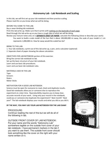
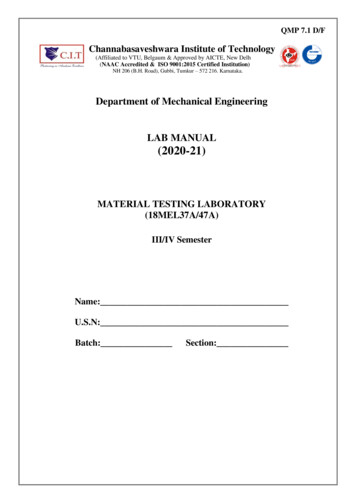
Material Testing Lab (18MEL37A/47A)III/IVFig. Universal Testing Machinelg gauge length i.e. length of the specimen on which we want to determine the mechanicalproperties.L Total length of the specimenDepartment of ME, CIT, Gubbi, TumkurPage. 1
Material Testing Lab (18MEL37A/47A)Experiment No: 1III/IVDate: / /TENSILE TESTAIM: To study the behavior of the given material under tensile load and to determine thefollowings: Percentage elongation in lengthPercentage reduction in areaWorking stress or permissible stress or safe stressYoung’s modulusYield stressUltimate stress or Maximum tensile stressBreaking stress or Failure stressPRACTICAL IMPORTANCE: while designing a component, selection of metals fordifferent applications is based on salient points such as limit of proportionality or elastic limit,yield strength, ultimate strength, and breaking strength. Therefore, from this tension test abovesaid salient points can be calculated.APPARATUS: Universal Testing machine, Dial gauge, Vernier caliper and scale.THEORY:In engineering, tension test is widely used to provide basic design information on thestrength of the materials. In the tension test a specimen is subjected to a continually increasinguniaxial tensile force while simultaneous observations are made of the elongation of thespecimen. A stress-strain curve is plotted from the load-elongation measurements.The parameters which are used to describe the stress-strain curve of a material are thetensile strength, yield strength or yield point, percent elongation and reduction of area. Thefirst two are strength parameters; the last two indicate ductility.DEFINITIONS:Limit of proportionality (A): It is the limiting value of the stress up to which stress isproportional to strain.Elastic limit: This is the limiting value of stress up to which if the material is stressed andthen released (unloaded), Strain disappears completely and the original length is regained.Upper Yield Point (B): This is the stress at which, the load starts reducing and the extensionincreases. This phenomenon is called yielding of material.Department of ME, CIT, Gubbi, TumkurPage. 2
Material Testing Lab (18MEL37A/47A)III/IVOBSERVATIONS: Least count of dial gauge 0.01mm. Specimen Material Initial length (li) . . mm Initial diameter (di) . . mm Initial Cross sectional Area (Ai ) .mm2 Yield Load (pY) .kNWhere ‘pY’ is the load at Yield point Breaking Load (pB) .Where ‘pB’ is the load at Breaking point. Ultimate Load (pu) kNWhere ‘pu’ is the Maximum load applied. Final length (lf) .mm Final diameter (df) .mm Final CS Area (A f) mm2Department of ME, CIT, Gubbi, TumkurkNPage. 3
Material Testing Lab (18MEL37A/47A)III/IVLower Yield Point (C): At this stage the stress remains same but strain increases for sometime.Ultimate Stress (D): This is the maximum stress the material can resist. At this stage crosssectional area at a particular section starts reducing very fast (fig.2). This is called neckformation.Breaking Point (E): The stress at which finally the specimen fails is called breaking point.Hooks law: Within the elastic limit, the stress is proportional to the strain for anIsentropic material.Fig. general stress - strain curve for mild steelmaterialsFig. stress-strain curve for differentA - Elastic Limit pointB - Upper Yield point.C - Lower Yield pointD -Ultimate Stress pointE -Breaking Stress pointThe tensile strength of a material is the maximum amount of tensile stress that it can takebefore failure, such as breaking or permanent deformation. Tensile strength specifies the pointwhen a material goes from elastic to plastic deformation. It is expressed as the minimumtensile stress (force per unit area) needed to split the material apart.There are three types of tensile strength:1. Yield strength - The stress a material can withstand without permanent deformation.2. Ultimate strength - The maximum stress a material can withstand.3. Breaking strength - The stress coordinate on the stress-strain curve at the point ofrupture.Tensile strength is a limit state of tensile stress that leads to tensile failure in one of twomanners:Department of ME, CIT, Gubbi, TumkurPage. 4
Material Testing Lab (18MEL37A/47A)III/IV1. Ductile failure - Yield as the first stage of failure, some hardening in the second stageand breakage after a possible "neck" formation.2. Brittle failure - Sudden breaking in two or more pieces at a low stress state.TABULAR COLUMN:Sl.No.Load(kN)Load (N)123456789101112131415Department of ME, CIT, Gubbi, TumkurExtension (δl )In mmStress inN/mm2StrainYoung’smodulus(N/mm2)E stressstrainResultfromthe graphPage. 5
Material Testing Lab (18MEL37A/47A)III/IVFig. 1Proof Resilience: It is defined as the "partial strain energy stored in the specimen from zeroupto elastic point". Graphically, it is the area bounded below the graph from zero up to elasticpoint. Hence proof resilience Approximately the Triangular area from zero up to elastic point(Fig: 1),Proof resilience [1/2* EP* WEP] kg- cm.Modulus of Resilence: It is defined as the “Total strain energy stored in the specimen from'zero upto the fracture point of the specimen”. Graphically, it is the area bounded below thegraph from zero upto the point of fracture From the Graph.Modulus of Resilience Triangular area Al Rectangular area A2 Remaining area A3Modulus of Resilience (AI A2 A2) kg.cmDepartment of ME, CIT, Gubbi, TumkurPage. 6
Material Testing Lab (18MEL37A/47A)III/IVCALCULATIONS:Load Stress Area Strain PAi .N/mm2Change in lengthOriginal Length Young’s modulus StressStrainδll .σϵ . N/mm2 (obtained from the graph)yield stress Working stress Factor of Safety. . . N/mm2 % Elongation Final length Initial lengthInitial length % reduction in Area Yield strength Initial area Final arealInitial areaYield loadInitial area Ultimate Tensile strength Breaking strength Department of ME, CIT, Gubbi, TumkurX100 pYAiInitial areaFinal Area X100 li(Ai – Af)Aix 100 .%x 100 % N/mm2Ultimate loadBreaking Load(l f – l i)pbAf puAi N/mm2 N/mm2Page. 7
Material Testing Lab (18MEL37A/47A)III/IVPROCEDURE: The original dimensions of the specimen like original diameter, gauge length etc. isto be measured.The specimen is mounted on the Universal Testing machine between the fixed andmovable jaws.The load range in the machine is adjusted to its maximum capacity (160 tonnes)The dial gauge is mounted on the machine at the appropriate positions and adjustedto zero.The machine is switched on and the tensile load is applied gradually.For every 5 KN of load, the readings of dial gauge is noted and tabulated.Remove the dial gauge at slightly below the expected load at yield point.Record the load at yield point, at the yield point the pointer on load scale willremain stationary for small interval of time and blue needle will come back by 2 or3 divisions that point is lower yield point.The specimen is loaded continuously up to the ultimate load (red needle will stops)where there is formation of cup and cone at neck in the specimen, which is to benoted.With further loading the specimen breaks, and breaking load is noted.The specimen is removed and final dimensions are measured.RESULTS AND CONCLUSIONS:1. Working stress .N/mm22. Young’s Modulus of specimen N/mm23. Yield stress . N/mm24. Ultimate tensile stress . N/mm25. Breaking stress . N/mm26. % reduction in Area .%7. % Elongation %Department of ME, CIT, Gubbi, TumkurPage. 8
Material Testing Lab (18MEL37A/47A)III/IVOBSERVATIONS:1. Least count of dial gauge 0.01mm.2. Specimen Material 3. Initial length (li) . . mm4. Initial diameter (di) . . mm5. Initial C/S Area (Ai ) .mm6. Ultimate Load (pu ) kNWhere ‘pu’ is the Maximum load applied.7. Final length (lf) .mm8. Final diameter (df) .mm9. Final Area (A f) mm2TABULAR COLUMN:Sl.No.Load(kN)LoadCompression(N)(δl )(mm)123456789101112131415Department of ME, CIT, Gubbi, TumkurStress(N/mm2)StrainYoung’smodulus(N/mm2)E stressstrainResultfromthe graphPage. 9
Material Testing Lab (18MEL37A/47A)Experiment No: 2III/IVDate: / /COMPRESSION TESTAIM: To study the behavior of the given material under Compressive load and to determinethe following: Modulus of elasticity Maximum Compressive strength or ultimate stress Percentage Decrease in length Percentage Increase in areaPRINCIPLE: Ductile materials attain a Bulge or a Barrel shape after reaching themaximum compression load. No fracture takes place and there is change in cross-section andcompression value remains the same on reaching the maximum load as shown in the fig.1. Forbrittle materials, there will be no change in the cross-sections or height of the specimen due tothe compression load. On reaching the maximum compression load, the specimen suddenlyfractures as shown in the Fig 2.APPARATUS: Universal Testing machine, Dial gauge, Vernier caliper and scale.THEORY:The compression test is just opposite to tension test, with regard to direction. However,there are certain practical difficulties which may induce error in this test. They are: Difficulty in applying truly axial load. There is always a tendency of the specimen to bend in addition to Contraction.To avoid these errors, usually the specimen for this test shall be short in length (not more than2 time the diameter)Department of ME, CIT, Gubbi, TumkurPage. 10
Material Testing Lab (18MEL37A/47A)III/IVCALCULATIONS:oStress o Strain LoadArea PAi .N/mm2Change in lengthOriginal Lengtho Young’s modulus graph)StressStraino % Decrease in Length o % Increase in area δllσ ϵ N/mm2 (obtained from theli lfliAf AiAi x 100 %x 100 .%o Ultimate Compressive strength Department of ME, CIT, Gubbi, Tumkurultimate loadintial area puAi N/mm2Page. 11
Material Testing Lab (18MEL37A/47A)III/IVIn a compression test, stress – strain curve is drawn up to the elastic limit of proportionality.Metals have approximately the same modulus of elasticity as in tension test. The curve, forductile materials, continues almost without limit as there is no fracture of the material due toits ductility and cross sectional area increases continuously with increase in load. Thespecimen will shorten and bulge out. Compression test is mainly used for testing brittlematerials such as cast iron, concrete etc. Brittle materials commonly fail along a diagonalplane due to shearing.Graph: Stress v/s StrainDepartment of ME, CIT, Gubbi, TumkurPage. 12
Material Testing Lab (18MEL37A/47A)Department of ME, CIT, Gubbi, TumkurIII/IVPage. 13
Material Testing Lab (18MEL37A/47A)III/IVPROCEDURE: The original dimensions of the specimen like original dia., gauge length etc. is tobe measured.The specimen is mounted on the Universal Testing machine between the fixed andmovable jaws.The load range in the machine is adjusted to its maximum capacity (300 kN)The dial gauge is mounted on the machine at the appropriate positions and adjustedto zero.The machine is switched on and the compressive load is applied gradually.For every 10 kN of load, the readings of dial gauge is noted and tabulated.Remove the dial gauge at slightly below the expected load at yield point.Record the load at yield point, at the yield point the pointer on load scale willremain stationary for small interval of time and blue needle will come back by 1 or2 divisions that point is lower yield point.The specimen is loaded continuously up to the ultimate load (red needle will stops)which is to be noted.The specimen is removed and final dimensions are measured.RESULTS AND CONCLUSIONS:1. Modulus of elasticity N/mm22. Maximum Compressive strength or ultimate stress .N/mm23. Percentage Decrease in length .%4. Percentage Increase in area .%Department of ME, CIT, Gubbi, TumkurPage. 14
Material Testing Lab (18MEL37A/47A)III/IVOBSERVATIONS :1. Diameter of specimen for single shear mm2. Diameter of specimen for double shear mmTABULATION:Sl. No.Load(P)Type ofShearKg-fNCross SectionalArea(mm2)Shear Stress(N/ mm2)CALCULATIONS:1. Shear Stress loadcross section area N/mm2(Single shear)2. Shear Stress (Double shear)load2 x cross section areaDepartment of ME, CIT, Gubbi, Tumkur N/mm2Page. 15
Material Testing Lab (18MEL37A/47A)III/IVExperiment No: 3Date: / /SHEAR TESTAIM: To determine the shear strength of the given standard specimen undersingle and double shear.APPARATUS: UTM, Vernier Calipers, Standard MS Specimen.THEORY:A shear stress acts parallel to a C/S plane where as tensile and compressive stresses act atnormal to the C/S plane. For direct shear test of metals, a bar is usually sheared in the samedevice that changes the position of the specimen while the remaining position is subject toload by suitable dies.PROCEDURE:1. Measure the diameter of the specimen.2. Fix the shear Specimen in the Single/Double Shear fixture.3. Keep the shear equipment on the fixed jaw of UTM and apply the load slowly at rightangles to the axis of piece through the central block.4. Note the load at fracture.RESULTS AND CONCLUSIONS:1. Shear stress in single shear N/mm22. Shear stress in double shear N/mm2Department of ME, CIT, Gubbi, TumkurPage. 16
Material Testing Lab (18MEL37A/47A)III/IVTABULAR COLUMN:Load(P)kNSl.NoDeflection( )mm(P/ )value123456Resultfromthe graph789101112OBSERVATIONS: Material . Span length(L) .mm Breadth (b) .mm Height (h) .mm Cross sectional area at centre b x h . mm2 Load at fracture, Pf .kNDepartment of ME, CIT, Gubbi, TumkurPage. 17
Material Testing Lab (18MEL37A/47A)Experiment No: 4III/IVDate: / /BENDING TESTAIM: To Conduct bending tests for the given specimen and to determine the following: Modulus of elasticity Modulus of Rupture or flexure modulus (maximum bending stress at failure usingbending equation).PRINCIPLE:A Bending test may be performed on actual beam cross-section by using the three pointloading system. The bending fixture is supported on the platform of the hydraulic cylinder ofthe universal testing machine. The loading knife edge is held in the middle crosshead. At aparticular load, the deflection at the centre of the beam is determined by using a dial gauge.The deflection at the beam centre is given by WL3/48EI. By knowing W, L, D and I, it ispossible to obtain the modulus of elasticity of beam material.APPARATUS: Universal Testing machine, Dial gauge, Vernier caliper and scale.THEORY:Application of a simple concentrated load at centre in the case of Bending associatedwith shear. Application of two concentrated loads will lead to pure bending without shear.Beams are usually subjected to bending moment and shearing forces which vary from sectionto section. Bending moment at a section in a beam is the moment that is trying to bend it and isobtained as the algebraic sum of the moments about the section of all the forces acting on thebeam either to the left or to the right of the section. Due to the bending moment, beam sags orhogs as shown below;Department of ME, CIT, Gubbi, TumkurPage. 18
Material Testing Lab (18MEL37A/47A)III/IVCALCULATIONS:Moment of inertia, I bℎ 3Section modulus (Z) . mm412I Ybℎ 26mm3 .From the graph, Load/ Deflection P / N/mm𝑃𝐿3Deflection (δ) 48EI . mmL3Young’s Modulus, E X ( P/ )48IMaximum Bending moment M {Slope of the load-deflection at yieldpoint. (Obtained from the graph)}PfL4 N-mmWhere,M Bending moment in N – mmI Moment of Inertia in mm4 b Bending Stress in N / mm2 (Mpa)y Distance from neutral axis to the outer most fiber in mm.E Young’s modulus in N / mm2 (Mpa)R Radius of curvature in mm.𝑀Bending Stress, b I * y N / mm2Where, y h / 2 . mm3Pf LModulus of rupture(f) N/ mm22𝑏ℎ 2OrModulu
07 Lab Lesson Plan viii-ix Exp.No Title of the Experiment Page No 1 Tensile test on Universal Testing Machine. 02 2 Compression test on Universal Testing Machine. 10 3 Shear test on Universal Testing Machine. 16 4 Bending Test on metallic and non-metallic specimens. 18 5 Torsion Test. 22 6 Izod Impact Test 30 7 Charpy Impact Test 34