Transcription
Operating InstructionsCO2 s product is for research use only.Not for clinical diagnosis or treatment of humans or animals.Please read the operating instructions carefully before using this product, and save the operatinginstructions for future use.See page 86 for all model numbers.
CONTENTSINTRODUCTIONPRECAUTIONS FOR SAFE OPERATIONLABELS ON INCUBATORENVIRONMENTAL CONDITIONSINCUBATOR COMPONENTSUnitLCD touch panelRemote alarm terminalINSTALLATIONInstallation siteInstallationConnecting CO2 gas cylinderBEFORE COMMENCING OPERATIONInitial cleaning methodRemoving inner attachmentsInstalling inner attachmentsFilling humidifying panFOR BETTER CULTIVATIONPrecautions for culturesPreventing contaminationCORRECT OPERATIONBASIC OPERATION ON LCD TOUCH PANELBASIC PARAMETERSNumerical input to input windowSetting temperature, CO2 density and high limit temperature alarmSetting key lockRemoving key lockALARM PARAMETERSOPERATION/ALARM LOGSetting log intervalDisplaying operation logExporting operation logDisplaying alarm logExporting alarm logOTHER PARAMETERSSetting date and timeSetting brightness and sleepSetting DAQP. 3P. 4P. 8P. 9P. 10P. 12P. 14P. 15P. 17P. 19P. 20P. 21P. 23P. 24P. 25P. 26P. 27P. 28P. 30P. 31P. 33P. 35P. 36P. 39P. 40P. 43P. 46P. 48P. 51P. 52P. 541
CONTENTSUV LAMP PARAMETERSUsing UV lampSetting UV lamp ON periodLighting UV lamp for 24 hoursH2O2 DECONTAMINATIONH2O2 decontaminationPrecautions when handling H2O2 reagentUsing unlock keyELECTRIC LOCK (OPTION)Setting auto lockUsing unlock keyRemoving auto lockGAS AUTO CHANGER (OPTION)Connecting CO2 gas cylinderAutomatic CO2 gas supply line changeoverManual CO2 gas supply line changeoverSTD GAS AUTO CALIBRATION KIT (OPTION)ROUTINE MAINTENANCEALARMS, SAFETY, AND SELF-DIAGNOSISTROUBLESHOOTINGDISPOSAL OF UNITSPECIFICATIONSPERFORMANCESAFETY CHECK SHEET2P. 55P. 55P. 56P. 58P. 60P. 61P. 65P. 65P. 66P. 66P. 67P. 68P. 69P. 69P. 70P. 72P. 73P. 76P. 77P. 80P. 83P. 84P. 86P. 87
INTRODUCTION Read the operating instructions carefully before using the Product and follow the instructions for safetyoperation. Our company disavows any responsibility for safety if the Product is used for other than the intended useor used with any procedures other than those given in the operating instructions. Keep the operating instructions in a suitable place so that it can be referred to as necessary. The contents of the operating instructions are subject to change without notice for improvement ofperformance or functions. Contact our sales representative or agent if any page of the operating instructions is lost or the pageorder is incorrect. Contact our sales representative or agent if any point in the operating instructions is unclear or if thereare any inaccuracies. No part of the operating instructions may be reproduced in any form without the expressed writtenpermission of our company. This product is for research use only. Not for clinical diagnosis or treatment of humans or animals.CAUTIONOur company guarantees the product under certain warranty conditions.way shall be responsible for any loss of content or damage of content.Our company in no3
PRECAUTIONS FOR SAFE OPERATIONIt is imperative that the user complies with the operating instructionsas it contains important safety advice.Items and procedures are described so that you can use this unit correctly and safely. Ifthe precautions advised are followed, this will prevent possible injury to the user and anyother person.Precautions are illustrated in the following way:WARNINGFailure to observe WARNING signs could result in a hazard to personnelpossibly resulting in serious injury or death.CAUTIONFailure to observe CAUTION signs could result in injury to personnel anddamage to the unit and associated property.Symbol shows;this symbol means caution.this symbol means an action is prohibited.this symbol means an instruction must be followed.Be sure to keep the operating instructions in a place accessible to users of this unit. Label on the unit This mark is labeled on the cover in which the electrical components of high voltage areenclosed to prevent the electric shock.The cover should be removed by a qualified engineer or a service personnel only.WARNINGAs with any equipment that uses CO2 gas, there is a likelihood of oxygen depletion in the vicinityof the equipment. It is important that you assess the work site to ensure there is suitable andsufficient ventilation. If restricted ventilation is suspected, then other methods of ensuring asafe environment must be considered. These may include atmosphere monitoring and warningdevices.4
WARNINGDo not use the unit outdoors. Current leakage or electric shock may result if the unit is exposed torain water.Only qualified engineers or service personnel should install the unit.unqualified personnel may cause electric shock or fire.The installation byInstall the unit on a sturdy floor and take an adequate precaution to prevent the unit fromturning over. If the floor is not strong enough or the installation site is not adequate, this may result ininjury from the unit falling or tipping over.Never install the unit in a humid place or a place where it is likely to be splashed by water.Deterioration of the insulation may result which could cause current leakage or electric shock.Never install the unit in a flammable or volatile location. This may cause explosion or fire.Never install the unit where acid or corrosive gases are present as current leakage or electricshock may result due to corrosion.Always ground (earth) the unit to prevent electric shock. If the power supply outlet is notgrounded, it will be necessary to install a ground by qualified engineers.Never ground the unit through a gas pipe, water main, telephone line or lightning rod. Suchgrounding may cause electric shock in the case of an incomplete circuit.Connect the unit to a power source as indicated on the rating label attached to the unit. Use ofany other voltage or frequency other than that on the rating label may cause fire or electric shock.Never store volatile or flammable substances in this unit if the container cannot be sealed. Thesemay cause explosion or fire.Do not insert metal objects such as a pin or a wire into any vent, gap or any outlet on the unit.This may cause electric shock or injury by accidental contact with moving parts.Use this unit in safe area when treating the poison, harmful or radiate articles. Improper usemay cause bad effect on your health or environment.Turn off the power switch (if provided) and disconnect the power supply to the unit prior to anyrepair or maintenance of the unit in order to prevent electric shock or injury.Do not touch any electrical parts (such as power supply plug) or operate switches with a wethand. This may cause electric shock.5
PRECAUTIONS FOR SAFE OPERATIONWARNINGEnsure you do not inhale or consume medication or aerosols from around the unit at the time ofmaintenance. These may be harmful to your health.Never splash water directly onto the unit as this may cause electric shock or short circuit.Never put containers with liquid on the unit as this may cause electric shock or short circuit whenthe liquid is spilled.Never bind, process, or step on the power supply cord, or never damage or break the powersupply plug. A broken supply cord or plug may cause fire or electric shock.Do not use the supply cord if its plug is loose. Such supply cord may cause fire or electric shock.Never disassemble, repair, or modify the unit yourself. Any such work carried out by anunauthorized person may result in fire, or electric shock or injury due to a malfunction.Disconnect the power supply plug if there is something wrong with the unit.abnormal operation may cause electric shock or fire.ContinuedWhen removing the plug from the power supply outlet, grip the power supply plug, not the cord.Pulling the cord may result in electric shock or fire by short circuit.Disconnect the power supply plug before moving the unit. Take care not to damage the power cord.A damaged cord may cause electric shock or fire.Disconnect the power plug when the unit is not used for long periods. Keeping the connectionmay cause electric shock, current leakage, or fire due to the deterioration of insulation.If the unit is to be stored unused in an unsupervised area for an extended period, ensure that childrendo not have access and that doors cannot be closed completely.The disposal of the unit should be accomplished by appropriate personnel. Remove doors toprevent accidents such as suffocation.Do not put the packing plastic bag within reach of children as suffocation may result.Use the reagent specified by our company for H2O2 decontamination. Using a different H2O2solution may result in explosion or damage to the incubator.When performing H2O2 decontamination, securely close the internal and external doors. Failure todo so may be harmful to health due to leakage of H2O2 gas.During H2O2 decontamination, plug the access hole with the silicon cap that is provided. Failure todo so may be harmful to health due to leakage of H2O2 gas.Always use the removal power supply cord that is provided. Other power supply cord may causeelectric shock or fire.6
CAUTIONThis unit must be plugged into a dedicated circuit protected by branch circuit breaker.Use a dedicated power source as indicated on the rating label attached to the unit. A multiple-tap maycause fire resulting from abnormal heating.Never store corrosive substances such as acid or alkali in this unit if the container cannot besealed. These may cause corrosion of inner components or electric parts.Check the setting when starting up of operation after power failure or turning off of powerswitch. The stored items may be damaged due to the change of setting.Be careful not to tip over the unit during movement to prevent damage or injury.Prepare a safety check sheet (copy the last page) when you request any repair or maintenance forthe safety of service personnel.Wear rubber gloves when handling the H2O2 reagent. Direct contact with the H2O2 reagent mayresult in inflammation of the skin.H2O2 decontamination can be performed only for the chamber and chamber attachments with standardspecifications, and not for any other objects.Perform H2O2 decontamination with the chamber attachments arranged as specified by ourcompany. Arranging them in a different way may result in insufficient decontamination.After H2O2 decontamination has been completed, wear rubber gloves and use a non-woven cloth towipe off the residual H2O2 fluid from the bottom of the chamber, any objects that weredecontaminated, and the bottoms of ducts.7
LABELS ON INCUBATORWarning and caution labels are attached to the incubator. The following table describes the labels.This label is attached to covers that access high-voltage electrical components toprevent electric shock. Only a qualified engineer or service personnel should beallowed to open these covers.This symbol indicates an ultraviolet light (UV) caution.This symbol indicates that caution is required. Refer to product documentation fordetails.This symbol indicates a hot surface.This symbol indicates an earth.This symbol means “ON” for a power switch.This symbol means “OFF” for a power switch.8
ENVIRONMENTAL CONDITIONSThis equipment is designed to be safe at least under the following conditions (based on the IEC-61010-1): Indoor use; Altitude up to 2000 m; Temperature 5oC to 40oC Maximum relative humidity 80% for temperature up to 31oC decreasing linearly to 50% relative humidityat 40oC; Mains supply voltage fluctuations up to 10% of the nominal voltage; Transient overvoltages up to the levels of OVERVOLTAGE CATEGORY Ⅱ; Temporary OVERVOLTAGES occurring on the mains supply; Applicable pollution degree of the intended environment (POLLUTION DEGREE 2 in most cases);9
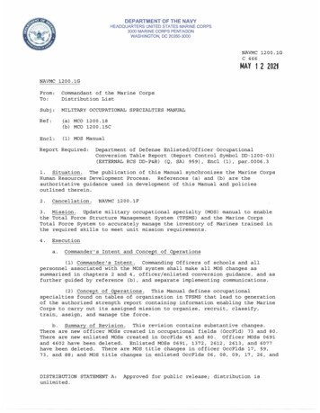
INCUBATOR COMPONENTSUnitRear leftAccess portcoverSilicon When some innerattachments are removed)67※ 1813212*2Electric key*1110 9*1: MCO-170AICUVHL/170AICUVL or when anoptional UV system set MCO-170UVS is installed.*2: MCO-170AICUVHL or when an optional electriclock MCO-170EL is installed.Lower right side(When 13 is removed)Sample air outlet capRemoval powersupply cord port18 17 16※1101514
1. Outer door: The outer door is held to the frame with the magnetic seal. The door heater is installed inthe door panel. The door opening is reversible. Contact our sales representative or agent to change thedoor hinge from left to right or vice versa.2. Inner door: The inner door is made of tempered glass. However do not subject the glass to excessiveimpacts.3. Tray catches: Insert tray to fit the concave portion on chamber.4. Fan cover: The fan cover serves as the inlet for circulating air. It is removable.5. Duct: The duct for the path for circulating air. It is removable.6. Fan (inside the duct): The fan is made from polypropylene resin. It can be disinfected in an autoclave.7. UV lamp*1: This UV lamp does not generate ozone. Never look directly at the UV light. For replacement,contact our sales representative or agent.8. Humidity control bar: Reduce automatically dew condensation occurred by the effect of outsideenvironment and the frequency of door opening/closing.The humidity control bar has bactericidal effects by plated surface of it. However, it is recommended toreplace the humidity control bar every 5 to 6 years to maintain bactericidal effects. (The durationof bactericidal effects differs depending on the use environment.)9. Humidifying pan cover: This cover prevents the UV light entering the chamber. Always use it. Usingwithout it may have a bad influence on the chamber temperature distribution and humidity recovery.10. Humidifying pan: Fill the humidifying pan with sterile distilled water. Install the humidifying pan in alongitudinal direction as its shorter side is placed in the back.11. Door switch: Detects the door opening/closing and stops the fan and electromagnetic valve for CO2when the door is open. The UV lamp*1 is also deactivated by the door opening.12. Key hole*2: This is the hole to unlock with unlock key while outer door is locked by electric lock.13. Switch cover: Prevent the accident of gas tube disconnected by the unexpected touch or power off.14. Power supply cord cover plate: This plate is to prevent the power cord being come off.15. Connecting port A for CO2 gas pipe: Refer to page 19 for gas cylinder connection. Ensure that thegas pressure is set at 0.03 MPa(G) (0.3 kgf/cm2(G), 4.3 psi(G)).Note: When the optional MCO-21GC gas auto changer is installed, both ports A and B are available. Referto page 69 for gas auto changer.16. Glow starter*1: The glow is started for the UV lamp. (Type FG-7P or FG-7PL)17. Power switch: This is the main switch for the incubator. It also functions as an overcurrent breaker.18. Sample air outlet: The sample air outlet also functions as an internal gas outlet. Normally, cover thisoutlet with the sample air outlet cap.19. USB port: Insert USB memory to export operations and alarms log. Refer to page 39 50.Note: It is impossible to use USB memory which is required password input.20. Access port: Place the silicon caps on both outside and inside of the port when the port is not beingused.21. Remote alarm terminals: This terminal informs the alarm to remote location by connecting to externalalarm unit. Refer to page 14.11
INCUBATOR COMPONENTSLCD touch panelThe following display (called the Top screen) will appear when the power switch is turned ON.Note: It takes approximately 20 seconds until Top screen is displayed.267835411. Present temperature display fieldThe current chamber temperature is displayed.This lamp lights when CO2 gas is beinginjected.2. Set temperature value display fieldThe set value of chamber temperature isdisplayed. Default setting: 37 oC7. CO2 gas supply line indicator A and B*1Current supplying CO2 gas supply line(connecting port for CO2 gas pipe) isdisplayed. The connecting port A/B for gaspipe that is currently supplying CO2 isdisplayed in reverse video and blinks.3. Heating indicatorThis lamp lights when the heater is energized.4. Present CO2 density display fieldThe current chamber CO2 density is displayed.Nothing is displayed when CO2 density is set 0%.5. Set CO2 density value display fieldThe set value of the chamber CO2 density isdisplayed. Default setting: 0 %8. CO2 gas supply line select key*1This is a key to select CO2 gas supply line Aor B (Connecting port A or B for CO2 gaspipe). When an optional gas auto chargerMCO-21GC is installed, CO2 gas supply lineA/B changes over automatically when CO2gas cylinder is empty. Changeover is alsoworkable by pressing this key.6. CO2 gas injection indicator*1: Only when an optional component MCO-21GC (Gas auto charger) is installed, this key is workable. Theyare not displayed when the MCO-21GC is not installed.12
10119131214181716159. Present date/time display fieldNormally, this indicator shows date and time.The date and time is simply set when theincubator is shipped from the factory. Refer topage 51 for details.12. Outer door (opening/closing) displayOpen: ”Door : Open” is displayed alternatelyin normal characters and reverse video.Close: ”Door : Closed” is displayed.Locked: ”Door : Locked” is displayed.*210. Over heat displayHigh limit temperature alarm is activated:”Over Heat” is displayed alternately in normalcharacters and reverse video.13. Message display fieldAlarms, errors or messages are displayedwhen fault occurs. Refer to page 77 79.11. UV lamp condition displayUV lamp ON: “UV : On” is displayed.UV lamp OFF: ”UV : Off” is displayed.Note: Nothing is displayed when an optionalUV system set MCO-170UVS is not installedto the MCO-170AICL.Note: When there are a number ofalarms/errors, the display shows the message.For example, if 2 alarms/errors occur in total,the display shows “1/2”.14. Message select keyWhen there are a number of alarm/erroros,the message on the screen is changeable.15. Menu keyPress this key to lead the Menu screen. It ispossible to set various setting on the Menuscreen. Refer to page 28.*2: Auto lock function by electric lock is workable under any of the following conditions. When the conditionis not fulfilled, “Door : Locked” or Unlock key are not displayed.・MCO-170AICUVHL.・When an optional electric lock MCO-170EL is installed.13
INCUBATOR COMPONENTS16. H2O2 key*3This key is to run H2O2 decontamination. Referto page 60 to 65.18. Buzzer keyPress this key to silence the buzzer. However,when the ring back is ON, the buzzer willsound again when the ring back passed andthe alarm state still continues. Refer to page37 38 and 77 79.17. Unlock key*2Press this key is to unlock the outer door whenit is auto-locked by electric lock. Refer to page66 to 68. When the auto lock function is OFF,this key is not displayed.Note: It is not possible to silence the buzzerfor the high limit temperature alarm.*3: The H2O2 decontamination function is workable under any of the following conditions. When the condition isnot fulfilled, the H2O2 key is not displayed on the LCD touch panel.・When an H2O2 generator MCO-HP is installed in the MCO-170AICUVHL.・When all H2O2 generator MCO-HP, H2O2 decon board MCO-170HB and electric lock MCO-170EL areinstalled in the MCO-170AICUVL.・When all UV system set MCO-170UVS, H2O2 generator MCO-HP, H2O2 decon board MCO-170HB andelectric lock MCO-170EL are installed in the MCO-170AICL.Remote alarm terminalThe alarm of this product can be informed at a remote location from this product by connecting the externalalarm unit to the remote alarm terminals. For the type and behavior of remote alarm output, refer to page77 to 79.The terminal of the remote alarm is installed at therear upper right of the unit (See the figure on thepoint). The alarm is outputted from this terminal.Contact capacity is DC 30 V, 2 A.When Buzzer key is pressed, the behavior of theremote alarm is showed in Table.1.Note: In the door alarm, the remote alarm does notwork. Refer to page 77 to 78.Remote alarmterminalTable 1 The behavior of the remote alarm when pressing the Buzzer keyRemote Alarm setting(Refer to page 36 38)ConnectingterminalNormalconditionAbnormal condition(Including in the cases of power outage andof where the power plug is pulled out.)When pressing the buzzer keyON:Non-interlock with Buzzer keyOFF:Interlock with Buzzer keyCOM.-N.C.CloseOpenOpen (Maintain in abnormality)*COM.-N.O.OpenCloseClose (Maintain in abnormality)*COM.-N.C.CloseOpenClose (Return to normal)COM.-N.O.OpenCloseOpen (Return to normal)*In case of Err01 (CO2 gas cylinder empty), Err11, 12(CO2 sensor error), the condition returns to normal.14
INSTALLATIONInstallation siteFor correct operation of the incubator, install it in a location with the following conditions.WARNINGWhen using CO2 gas for control, make sure that there is an adequate ventilation. Using CO2 gas in asmall room without adequate ventilation may cause gas poisoning or oxygen deprivation. In addition, whenopening the incubator doors, do not directly inhale the air in the chamber.Si l’appareil est utilisé dans un evdroit restreint, le niveau de la densite CO2 de l’air peut s’élever et peutêtre nocif aux humains. Evitez d’aspirer l’air provenant de l’inérieur de l’appareil quand vous ouverz laporte. Normal air environmentInstall the incubator in an environment with normal air. Do not expose to direct sunlightDo not install the incubator in a location where it will be exposed to direct sunlight. If the incubator isoperated in direct sunlight, performance will be adversely affected. Separate from heat sourcesDo not install the incubator near significant heat sources, such as heaters, boilers, ovens, or autoclaves.Heat will adversely affect the performance of the incubator. Ambient temperature at least 5 C lower than set temperatureThe control temperature of the incubator is at least 5 C higher than the ambient temperature. For example,if the chamber is controlled at 37 C, the ambient temperature must be 32 C or less. Do not allow theambient temperature to become too high. Strong and level floorSelect a site with a strong and level floor. If the floor is uneven or the installation is not level, the incubatorwill be unstable and this may cause accident or injury. To avoid vibration and noise, always make sure thatthe installation is stable. An unstable surface may result in vibration or noise.WARNINGInstall the incubator at a location that can support the weight. If the floor is not strong enough or if theinstallation is insufficient, the incubator may fall over and cause injury.Always make sure that the floor is strong, even, and level, and that the incubator will not tip over.An insufficient installation may result in injury due to water leakage or the incubator falling over. Low humiditySelect a site with a relative humidity of 80 %R.H. or lower. Using the incubator in high humidity may resultin current leakage or electric shock.WARNINGDo not use the incubator outdoors. If the incubator is exposed to rain water, it may result in currentleakage or electric shock.Never install the incubator in a moist location, such as near a sink or water line, or where it is likelyto be exposed to water. In addition, do not install it near water or steam pipes. Moisture can cause theinsulation to deteriorate, which may result in current leakage or electric shock.15
INSTALLATION No inflammable or corrosive gasNever install the incubator in a location where it will be exposed to inflammable or corrosive gas. Doing somay result in explosion or fire. In addition, insulation may deteriorate due to corrosion of protective casing,resulting in current leakage or electric shock. No falling objectsDo not install the incubator in a location where there is the possibility of objects falling from above. Doingso may result in damage or accident.16
Installation1. Remove the packing tape and clean up.Remove all the tapes that are securing the doors and the inner attachments. Open the doors for ventilation.If the outer panels are dirty, wet a cloth with a diluted neutral detergent and wipe them. (Undiluteddetergent can damage the plastic components. For the dilution, refer to the instruction of the detergent.)Wipe off the residual detergent with a wet cloth and then wipe off any moisture.Note: Remove the cable tie banding the power supply cord. Prolonged banding may cause the corrosionof the cord coating.WARNINGDo not leave the plastic wrapping bags within reach of children. If the bag is placed over a child’shead, it can block the mouth and nose and cause suffocation.2. Adjust the leveling feet.Adjust the leveling feet by turning themcounterclockwise to level the incubator. (See theillustration on the right.)Note: Incubating on a leaning tray may have a badinfluence on the cultivation.ShrinkLeveling feetStrech3. Ground the incubator.Ground the incubator during installation to prevent electric shock in case the insulation is not sufficient. Ifthere is no ground wire at the location, consult with qualified service personnel. When a ground must be installedIf a grounded 3-pole outlet is not available, then a ground must be installed. Consult with qualified servicepersonnel.WARNINGTo prevent electric shock, always ground the incubator. If grounding is not possible, then have a groundinstalled by qualified personnel. If the incubator is not grounded, it may result in electric shock.Never connect the ground wire to a gas pipe, water pipe, lightning rod, or telephone ground wire.Doing so may cause electric shock. Installing a ground fault circuit breakerIf using the incubator in the location with moisture or humidity cannot be avoided, then it is recommendedthat a ground fault circuit breaker be installed in the power supply circuit (i.e., the power supply at theincubator). Have the circuit breaker installed by qualified service personnel.17
INSTALLATIONCAUTIONDo not climb on the incubator or place objects on top of it. Doing so may damage it or cause it to fallover, resulting in injury. In case of double stackFor stacking the incubators surely, refer to theprocedure included with the optional doublestacking bracket MCO-170PS or the stacking plateMCO-170SB.HooksWireNote: Two hooks are attached to the rear of theupper incubator. When stacking incubators, fix theupper incubator to the wall with these hooks andwire or chain (See the figure on the point).Note: When stacking the incubators on our CO2incubator or O2/CO2 incubator other than thisproduct, use the stacking plate MCO-170SB. Referto table 11 on page 85. When the incubator is not in useEmpty the water from the humidifying pan and remove moisture from the chamber. Make sure that thechamber is completely dry before closing the doors. Failure to do so may result in damage. Before moving the incubatorBefore moving the incubator, empty the water from the humidifying pan, disconnect the power supply plugfrom the outlet, and make sure that the cord will not be damaged. Failure to do so may result in electricshock or fire.18
Connecting CO2 gas cylinderWARNINGWhen connecting a gas cylinder to the incubator, confirm the gas type. Confirm that the connectionsare secure and that no gas will leak. Be sure to use the specified pressure. Using an incorrect gas orpressure may result in explosion or fire, or in gas poisoning or oxygen deprivation due to qas leak.Install the incubator in a location with adequate ventilation. If adequate ventilation cannot be provided,then install an alarm system using CO2 and O2 densitometers.1. Get a CO2 gas cylinder ready and install an optional gas regulator MCO-100L.Note:・Use a liquefied CO2 gas cylinder (at least 99.5 % pure). The siphon (dip tube) type cannot be used.・When MCO-100L is not available, install a gas regulator rated at 25 MPa(G) (250 kgf/cm2(G), 3600psi(G)) for the primary side, and 0.2 MPa(G) (2 kgf/cm2(G), 30 psi(G)) for the secondary side.2. Using a gas tube that is provided, connect theconnecting port A for CO2 gas pipe and the gasregulator of the CO2 gas cylinder.For details on installing the optional automatic CO2cylinder changeover kit (MCO-21GC), refer to page69 71.Lower right sideConnecting port A for CO2 gas pipeNote: If the CO2 gas is supplied to multiple CO2 incubators from a single gas cylinder, a CO2 solid will beformed in the gas regulator. The gas regulator safety valve will operate, and there may an explosivesound.3. After connecting the gas tube, make sure that no gas is leaking.4. Set the CO2 gas on the secondary side to 0.03 MPa(G) (0.3 kgf/cm2(G), 4.3 psi(G)) for gas injection.Note: As the pressure increases, the CO2 gas density control range will increase. Excessive pressure maycause gas supply lines inside the incubator to come loose, which may result in gas poisoning or oxygendeprivation due to gas leak. If gas lines come loose, the incubator must be repaired.5. When there is no CO2 gas left and the CO2 gas empty alarm is activated, replace the empty gas cylinderto a new one.Note: When an optional gas auto changer MCO-21GC is installed, it switches the empty CO2 gas supplyline to the other automatically. Refer to page 69 71.Note: The gas lines connected to the incubator will degrade over time. If any deterioration or abnormalitiesare found during inspection, replace the lines immediately.19
BEFORE COMMENCING OPERATIONInitial cleaning methodBefore using the incubator for the first time, clean dirt (tape residue, smear, etc.) from thechamber and the inner attachments thoroughly. To keep the chamber clean is essential toget the proper performance out of the incubator. Use the following steps to clean theincubator properly.1. Remove the inner attachments, referring to “Removing inner attachments” on page 21.2. Clean the removed inner attachments, the chamber inside walls and the
STD GAS AUTO CALIBRATION KIT (OPTION) P. 73 ROUTINE MAINTENANCE P. 76 ALARMS, SAFETY, AND SELF-DIAGNOSIS P. 77 TROUBLESHOOTING P. 80 DISPOSAL OF UNIT P. 83 SPECIFICATIONS P. 84 PERFORMANCE P. 86 SAFETY CHECK SHEET P. 87 . 3 INTRODUCTION Read the operating instructions carefully before using the Product and follow the instructions for safety .