Transcription
Chapter 12: Radiation Heat TransferRadiation differs from Conduction and Convection heat t transfer mechanisms, inthe sense that it does not require the presence of a material medium to occur.Energy transfer by radiation occurs at the speed of light and suffers no attenuationin vacuum.Radiation can occur between two bodies separated by a medium colder than bothbodies.According to Maxwell theory, energy transfer takes place via electromagneticwaves in radiation. Electromagnetic waves transport energy like other waves andtravel at the speed of light.Electromagnetic waves are characterized by their frequency ν (Hz) andwavelength λ (µm), where:λ c/νwhere c is the speed of light in that medium; in a vacuum c0 2.99 x 10⁸ m / s.Note that the frequency and wavelength are inversely proportional.The speed of light in a medium is related to the speed of light in a vacuum,c c0 / nwhere n is the index of refraction of the medium, n 1 for air and n 1.5 for water.Note that the frequency of an electromagnetic wave depends only on the sourceand is independent of the medium.The frequency of an electromagnetic wave can range from a few cycles to millionsof cycles and higher per second.Einstein postulated another theory for electromagnetic radiation. Based on thistheory, electromagnetic radiation is the propagation of a collection of discretepackets of energy called photons. In this view, each photon of frequency ν isconsidered to have energy ofe hν hc / λwhere h 6.625 x 10⁻³⁴J.s is the Planck’s constant.Note that in Einstein’s theory h and c are constants, thus the energy of a photon isinversely proportional to its wavelength. Therefore, shorter wavelength radiationpossesses more powerful photon energies (X-ray and gamma rays are highlydestructive).Chapter 12, E&CE 309, Spring 2005.Majid Bahrami1
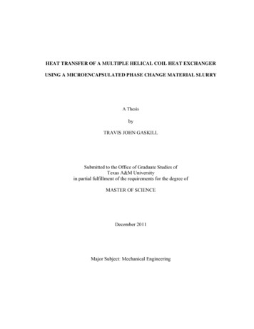
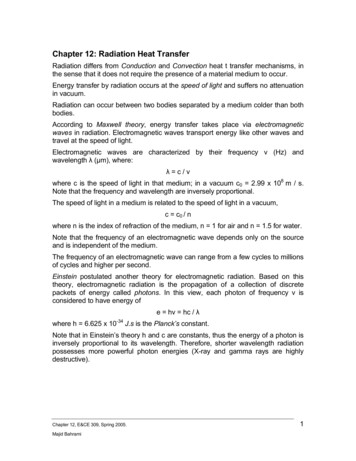
Fig. 12-1: Electromagnetic spectrum.Electromagnetic radiation covers a wide range of wavelength, from 10-10 µm forcosmic rays to 1010 µm for electrical power waves.As shown in Fig. 12-1, thermal radiation wave is a narrow band on theelectromagnetic wave spectrum.Thermal radiation emission is a direct result of vibrational and rotational motions ofmolecules, atoms, and electrons of a substance. Temperature is a measure ofthese activities. Thus, the rate of thermal radiation emission increases withincreasing temperature.What we call light is the visible portion of the electromagnetic spectrum which lieswithin the thermal radiation band.Thermal radiation is a volumetric phenomenon. However, for opaque solids suchas metals, radiation is considered to be a surface phenomenon, since the radiationemitted by the interior region never reach the surface.Note that the radiation characteristics of surfaces can be changed completely byapplying thin layers of coatings on them.Blackbody RadiationA blackbody is defined as a perfect emitter and absorber of radiation. At aspecified temperature and wavelength, no surface can emit more energy than ablackbody.A blackbody is a diffuse emitter which means it emits radiation uniformly in alldirection. Also a blackbody absorbs all incident radiation regardless of wavelengthand direction.Chapter 12, E&CE 309, Spring 2005.Majid Bahrami2
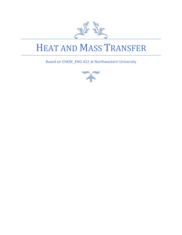
The radiation energy emitted by a blackbody per unit time and per unit surfacearea can be determined from the Stefan-Boltzmann Law:Eb σT 4(W / m )2whereσ 5.67 10 8Wm2 K 4where T is the absolute temperature of the surface in K and Eb is called theblackbody emissive power.A large cavity with a small opening closely resembles a blackbody.Fig. 12-2: Variation of blackbody emissive power with wavelengthSpectral blackbody emissive power is the amount of radiation energy emitted by ablackbody at an absolute temperature T per unit time, per unit surface area, andper unit wavelength. W 2 m .µm C1 2πhc02 3.742 10 8 W .µm 4 / m 2Ebλ (T ) C1λ [exp(C 2 / λT ) 1]5(C 2 hc 0 / k 1.439 10 4 (µm.K ))k 1.3805 10 23 ( J / K ) Boltzmann's constantThis is called Plank’s distribution law and is valid for a surface in a vacuum or gas.For other mediums, it needs to be modified by replacing C1 by C1/n2, where n isthe index of refraction of the medium,Chapter 12, E&CE 309, Spring 2005.Majid Bahrami3
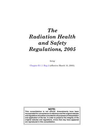
The wavelength at which the peak emissive power occurs for a given temperaturecan be obtained from Wien’s displacement law:(λT )max power 2897.8 µm.KIt can be shown that integration of the spectral blackbody emissive power Ebλ overthe entire wavelength spectrum gives the total blackbody emissive power Eb: Eb (T ) Ebλ (T )dλ σT 4(W / m )20The Stefan-Boltzmann law gives the total radiation emitted by a blackbody at allwavelengths from 0 to infinity. But, we are often interested in the amount ofradiation emitted over some wavelength band.To avoid numerical integration of the Planck’s equation, a non-dimensionalquantity fλ is defined which is called the blackbody radiation function asλf λ (T ) E λ (T )dλb0σT 4The function fλ represents the fraction of radiation emitted from a blackbody attemperature T in the wavelength band from 0 to λ. Table 12-2 in Cengel book listsfλ as a function of λT.Therefore, one can write:f λ1 λ 2 (T ) f λ 2 (T ) f λ1 (T )f λ (T ) 1 f λ (T )EbλEbλ(T)λ1λ2λFig. 12-3: Fraction of radiation emitted in the wavelength between λ1 and λ2Chapter 12, E&CE 309, Spring 2005.Majid Bahrami4
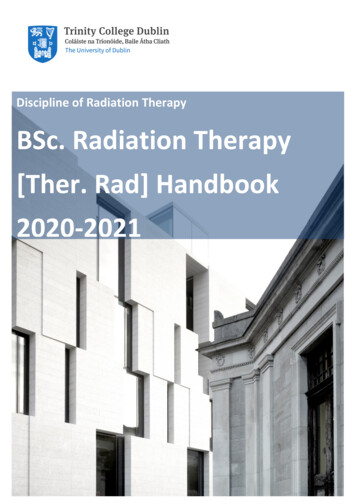
Example 12-1The temperature of the filament of a light bulb is 2500 K. Assuming the filament tobe a blackbody, determine the fraction of the radiant energy emitted by thefilament that falls in the visible range. Also determine the wavelength at which theemission of radiation from the filament peaks.SolutionThe visible range of the electromagnetic spectrum extends from 0.4 to 0.76 micrometer. Using Table 12-2:λ1T 0.4 µm(2500 K ) 1000µm.K f λ1 0.000321λ 2T 0.76µm(2500 K ) 1900 µm.K f λ 2 0.053035f λ 2 f λ1 0.05271which means only about 5% of the radiation emitted by the filament of the lightbulb falls in the visible range. The remaining 95% appears in the infrared region orthe “invisible light”.Radiation PropertiesA blackbody can serve as a convenient reference in describing the emission andabsorption characteristics of real surfaces.EmissivityThe emissivity of a surface is defined as the ratio of the radiation emitted by thesurface to the radiation emitted by a blackbody at the same temperature. Thus,0 ε 1Emissivity is a measure of how closely a surface approximate a blackbody,εblackbody 1.The emissivity of a surface is not a constant; it is a function of temperature of thesurface and wavelength and the direction of the emitted radiation, ε ε (T, λ, θ)where θ is the angle between the direction and the normal of the surface.The total emissivity of a surface is the average emissivity of a surface over alldirection and wavelengths:ε (T ) E (T ) E (T ) E (T ) ε (T ) σ T 4Eb (T ) σ T 4Spectral emissivity is defined in a similar manner:ε λ (T ) E λ (T )Ebλ (T )where Eλ(T) is the spectral emissive power of the real surface. As shown, theradiation emission from a real surface differs from the Planck’s distribution.Chapter 12, E&CE 309, Spring 2005.Majid Bahrami5
Fig. 12-4: Comparison of the emissive power of a real surface and a blackbody.To make the radiation calculations easier, we define the following approximations:Diffuse surface: is a surface which its properties are independent of direction.Gray surface: is a surface which its properties are independent from wavelength.Therefore, the emissivity of a gray, diffuse surface is the total hemispherical (orsimply the total) emissivity of that surface.A gray surface should emit as much as radiation as the real surface it representsat the same temperature: ε (T ) ε λ (T )E λ (T )dλb0σT4Emissivity is a strong function of temperature, see Fig. 12-20 Cengel book.Absorptivity, Reflectivity, and TransmissivityThe radiation energy incident on a surface per unit area per unit time is calledirradiation, G.Absorptivity α: is the fraction of irradiation absorbed by the surface.Reflectivity ρ: is the fraction of irradiation reflected by the surface.Transmissivity τ: is the fraction of irradiation transmitted through the surface.Radiosity J: total radiation energy streaming from a surface, per unit area per unittime. It is the summation of the reflected and the emitted radiation.Chapter 12, E&CE 309, Spring 2005.Majid Bahrami6
absorptivity :reflectivity :transmissivity :absorbed radiation Gabs incident radiationGreflected radiation Grefρ incident radiationGtransmitted radiation Gtrτ Gincident radiationα 0 α 10 ρ 10 τ 1Applying the first law of thermodynamics, the sum of the absorbed, reflected, andthe transmitted radiation radiations must be equal to the incident radiation:Gabs Gref Gtr GDivide by G:α ρ τ 1Radiosity, J(Reflected Emitted radiation)IncidentradiationG, W/m2ReflectedρGEmitted radiationε τGFig. 12-5: The absorption, reflection, and transmission of irradiation by a semitransparent material.For opaque surfaces τ 0 and thus: α ρ 1. The above definitions are for totalhemi-spherical properties (over all direction and all frequencies). We can alsodefine these properties in terms of their spectral counterparts:Chapter 12, E&CE 309, Spring 2005.Majid Bahrami7
Gλ ρ λ Gλ τ λ Gλ α λ Gλwhereρ λ ρ λ (T , λ )spectral reflectivityα λ α λ (T , λ )τ λ τ λ (T , λ )spectral absorptivityspectral transmissivitythus1 ρλ τ λ α λNote that the absorptivity α is almost independent of surface temperature and itstrongly depends on the temperature of the source at which the incident radiationis originating. For example α of the concrete roof is about 0.6 for solar radiation(source temperature 5762 K) and 0.9 for radiation originating from thesurroundings (source temperature 300 K).Kirchhoff’s LawConsider an isothermal cavity and a surface at the same temperature T. At thesteady state (equilibrium) thermal conditionGabs α G α σ T4and radiation emittedEemit ε σ T4Since the small body is in thermal equilibrium, Gabs Eemitε(T) α(T)The total hemispherical emissivity of a surface at temperature T is equal to its totalhemi-spherical absorptivity for radiation coming from a blackbody at the sametemperature T. This is called the Kirchhoff’s law.TGTEemitA, ε, αFig. 12-6: Small body contained in a large isothermal cavity.The Kirchhoff’s law can be written in the spectral form:Chapter 12, E&CE 309, Spring 2005.Majid Bahrami8
ε λ (T ) α λ (T )and in the spectral directional formε λ ,θ (T ) α λ ,θ (T )The Kirchhoff’s law makes the radiation analysis easier (ε α), especially foropaque surfaces where ρ 1 – α.Note that Kirchhoff’s law cannot be used when there is a large temperaturedifference (more than 100 K) between the surface and the source temperature.Solar RadiationThe solar energy reaching the edge of the earth’s atmosphere is called the solarconstant:Gs 1353 W / m2Owing to the ellipticity of the earth’s orbit, the actual solar constant changesthroughout the year within /- 3.4%. This variation is relatively small; thus Gs isassumed to be a constant.The effective surface temperature of the sun can be estimated from the solarconstant (by treating the sun as a blackbody).The solar radiation undergoes considerable attenuation as it passes through theatmosphere as a result of absorption and scattering:Absorption by the oxygen occurs in a narrow band about λ 0.76 µm.The ozone layer absorbs ultraviolet radiation at wavelengths below λ 0.3 µmalmost completely and radiation in the range of 0.3 – 0.4 µm considerably.Absorption in the infrared region is dominated by water vapor and carbondioxide. Dust/pollutant particles also absorb radiation at various wavelengths.As a result the solar radiation reaching the earth’s surface is about 950 W/m2on a clear day and much less on a cloudy day, in the wavelength band 0.3 to2.5 µm.Scattering and reflection by air molecules (and other particles) are othermechanisms that attenuate the solar radiation. Oxygen and nitrogen moleculesscatter radiation at short wavelengths (corresponding to violet and blue colors).That is the reason the sky seems blue!The gas molecules (mostly CO2 and H2O) and the suspended particles in theatmosphere emit radiation as well as absorbing it. It is convenient to consider theatmosphere (sky) as a blackbody at some lower temperature. This fictitioustemperature is called the effective sky temperature Tsky.Gsky σ T4skyTsky 230 K for cold clear skyChapter 12, E&CE 309, Spring 2005.Majid Bahrami9
Tsky 285 K for warm cloudy skyUsing Kirchhoff’s law we can write α ε since the temperature of the sky is on theorder of the room temperature.The View FactorRadiation heat transfer between surfaces depends on the orientation of thesurfaces relative to each other as well as their radiation properties andtemperatures.View factor (or shape factor) is a purely geometrical parameter that accounts forthe effects of orientation on radiation between surfaces.In view factor calculations, we assume uniform radiation in all directions throughoutthe surface, i.e., surfaces are isothermal and diffuse. Also the medium betweentwo surfaces does not absorb, emit, or scatter radiation.Fi j or Fij the fraction of the radiation leaving surface i that strikes surface jdirectly.Note the following:The view factor ranges between zero and one.Fij 0 indicates that two surfaces do not see each other directly. Fij 1indicates that the surface j completely surrounds surface i.The radiation that strikes a surface does not need to be absorbed by thatsurface.Fii is the fraction of radiation leaving surface i that strikes itself directly. Fii 0 forplane or convex surfaces, and Fii 0 for concave surfaces.Plane surface,Fii 0Convex surface,Fii 0Concave surface,Fii 0Fig. 12-7: View factor between surface and itself.Calculating view factors between surfaces are usually very complex and difficult toperform. View factors for selected geometries are given in Table 12-4 and !2-5 andFigs. 12-41 to 12-44 in Cengel book.Chapter 12, E&CE 309, Spring 2005.Majid Bahrami10
View Factor RelationsRadiation analysis of an enclosure consisting of N surfaces requires thecalculations of N2 view factors. However, all of these calculations are notnecessary. Once a sufficient number of view factors are available, the rest of themcan be found using the following relations for view factors.The Reciprocity RuleThe view factor Fij is not equal to Fji unless the areas of the two surfaces are equal.It can be shown that:Ai Fij Aj FjiThe Summation RuleIn radiation analysis, we usually form an enclosure. The conservation of energyprinciple requires that the entire radiation leaving any surface i of an enclosure beintercepted by the surfaces of enclosure. Therefore,N Fj 1ij 1The summation rule can be applied to each surface of an enclosure by varying ifrom 1 to N (number of surfaces). Thus the summation rule gives N equations.Also reciprocity rule gives 0.5 N (N-1) additional equations. Therefore, the totalnumber of view factors that need to be evaluated directly for an N-surfaceenclosure becomes1 1N 2 N N ( N 1) N ( N 1)2 2Example 12-2Determine the view factors F12 and F21 for the following geometries:DL DA1A1A1A2LA21LA2A32A331) Sphere of diameter D inside a cubical box of length L D.Chapter 12, E&CE 309, Spring 2005.Majid Bahrami11
2) Diagonal partition within a long square duct.3) End and side of a circular tube of equal length and diameter, L D.Assumptions:Diffuse surfaces.Solution:1) sphere within a cube:By inspection,F12 1By reciprocity and summation:F21 A1πD 2πF12 1 2A266LF21 F22 1 F22 1 π62) Partition within a square duct:From summation rule, F11 F12 F13 1By symmetrywhere F11 0F12 F13Thus, F12 0.5.From reciprocity:F21 A12LF12 0.5 0.71A2L3) Circular tube: from Fig. 12-43, with r2 / L 0.5 and L / r1 2, F13 0.17.From summation rule,F11 F12 F13 1with F11 0, F12 1 - F13 0.83From reciprocity,F21 A1πD 2 / 4F12 0.83 0.21A2πDLThe Superposition RuleThe view factor from a surface i to a surface j is equal to the sum of the viewfactors from surface i to the parts of surface j.Chapter 12, E&CE 309, Spring 2005.Majid Bahrami12
33 22111Fig. 12-8: The superposition rule for view factors.F1 (2,3) F1 2 F1 3The Symmetry RuleTwo (or more) surfaces that possess symmetry about a third surface will haveidentical view factors from that surface.Example: 12-3Find the view factor from the base of a pyramid to each of its four sides. The baseis a square and its side surfaces are isosceles triangles.From symmetry rule, we have:F12 F13 F14 F15Also, the summation rule yields:F11 F12 F13 F14 F15 1Since, F11 0 (flat surface), we find; F12 F13 F14 F15 0.2534251Pyramid in example 12-2.Chapter 12, E&CE 309, Spring 2005.Majid Bahrami13
The Crossed-Strings MethodGeometries such as channels and ducts that are very long in one direction can beconsidered two-dimensional (since radiation through end surfaces can beneglected). The view factor between their surfaces can be determined by crossstring method developed by H. C. Hottel, as follows:Fi j (crossed strings ) (uncrossed strings )2 (string on surface i )21L2DCL1L5L6L4L3L3L1L6L5L4BL2A21Fig. 12-9: Cross-string method.F12 (L5 L6 ) (L3 L4 )2L1Note that the surfaces do not need to be flat.Radiation Heat TransferThe analysis of radiation exchange between surfaces is complicated because ofreflection. This can be simplified when surfaces are assumed to be black surfaces.The net radiation between two surfaces can be expressed as radiation leaving surface 1 radiation leaving surface 2 Q 12 that directly stikes surface 2 that directly stikes surface 1 Q 12 A1 F12 Eb1 A2 F21 Eb 2(W )Applying reciprocity A1 F12 A2 F21 yields (Q 12 A1 F12σ T14 T24) (W )Consider an enclosure consisting of N black surfaces maintained at specifiedtemperatures. For each surface i, we can writeChapter 12, E&CE 309, Spring 2005.Majid Bahrami14
N (N Q i Q ij Ai Fij σ Ti 4 T j4j 1)(W )j 1Using the sign convention, a negative heat transfer rate indicates that the radiationheat transfer is to surface i (heat gain).Now, we can extend this analysis to non-black surfaces. It is common to assumethat the surfaces are opaque, diffuse, and gray. Also, surfaces are considered tobe isothermal. Also the fluid inside the cavity is not participating in the radiation.Radiosity J is the total radiation energy streaming from a surface, per unit area perunit time. It is the summation of the reflected and the emitted radiation.For a surface i that is gray and opaque (εi αi and αi ρi 1), the Radiosity can beexpressed asJ i ε i E bi ρ i GiJ i ε i E bi (1 ε i )GiJ i ε i Ebi σTi 4(W / m )2(for a blackbody)Note that the radiosity of a blackbody is equal to its emissive power.Using an energy balance, the net rate of radiation heat transfer from a surface i ofsurface area Ai can be expressed as Q i Ai ( J i Gi )(W ) J ε i EbiQ i Ai J i i1 εi Ai ε i (Ebi J i ) 1 εiIn electrical analogy to Ohm’s law, a thermal resistance can be defined asQi Ebi J iRiRi 1 εiAi ε i where Ri is called the surface resistance to radiation.Q iSurface iEbiJiFig. 12-10: Surface resistance to radiation.Chapter 12, E&CE 309, Spring 2005.Majid Bahrami15
Note that the surface resistance to radiation for a blackbody is zero.For insulated or adiabatic surfaces, the net heat transfer through them is zero. Inthis cases, the surface is called reradiating surface. There is no net heat transfer toa reradiating surface.Net Radiation between Two SurfacesConsider two diffuse, gray, and opaque surfaces of arbitrary shape maintained atuniform temperatures. The net rate of radiation heat transfer from surface i tosurface j can be expressed (W )Q ij Ai J i Fij A j J j F jiApplying reciprocityQij Ai Fij (J i J j ) (W )In analogy with Ohm’s law, a resistance can be defined as Qij Rij Ji J jRij1Ai Fijwhere Rij is called the space resistance to radiation.EbiQ ijJiRiJjRijEbjRjSurface jSurface iFig. 12-11: Electrical network, surface and space resistances.In an N-surface enclosure, the conservation of energy principle requires that thenet heat transfer from surface i to be equal to the sum of the net heat transfersfrom i to each of the N surfaces of the enclosure. N NJi J jj 1RijQ i Q ij j 1(W )We have already derived a relationship for the net radiation from a surfaceChapter 12, E&CE 309, Spring 2005.Majid Bahrami16
Qi Ebi J iRi(W )Combining these two relationships gives:N J JEbi J iij RiRijj 1(W )Method of Solving Radiation ProblemIn radiation problems, either the temperature or the net rate of heat transfer mustbe given for each of the surfaces to obtain a unique solution for the unknownsurface temperature and heat transfer rates.We use the network method which is based on the electrical network analogy.The following steps should be taken:1. Form an enclosure; consider fictitious surface(s) for openings, room, etc.2. Draw a surface resistance associated with each surface of the enclosure3. Connect the surface resistances with space resistances4. Solve the radiations problem (radiosities) by treating it as an electricalnetwork problem.Note that this method is not practical for enclosures with more than 4 surfaces.Example 12-4: Hot Plates in RoomTwo parallel plates 0.5 by 1.0 m are spaced 0.5 m apart. One plate is maintainedat 1000 C and the other at 500 C. The emissivities of the plates are 0.2 and 0.5,respectively. The plates are located in a very large room, the walls of which aremaintained at 27 C. The plates exchange heat with each other and with the room,but only the plate surfaces facing each other are to be considered in the analysis.Find the net heat transfer rate to each plate and the room; neglect other modes ofheat transfer, i.e., conduction and convection.Assumptions:Diffuse, gray, and opaque surfaces and steady-state heat transfer.Solution:This is a three-body problem, the two plates and room. The radiation network isshown below.Chapter 12, E&CE 309, Spring 2005.Majid Bahrami17
3 roomat 27 CT1 1000 C0.5 m0.5 m11.0 mT2 1000 C2Fig. 12-12: Schematic for Problem 12-4where,T1 1000 C 1273 KA1 A2 0.5 m2T2 500 C 773 KT3 27 C 300 Kε1 0.2ε2 0.5R12J1Eb1Q 1J2Eb2R2R1R13Q 2R23Q 3Eb3 J3 σT43Fig. 12-12: Thermal network for Problem 12-4.We can assume that the room is a blackbody, since its surface resistance isnegligible:R3 1 ε3 0A3ε 3A3 From Fig. 12-41 in Cengel book, the shape factor F12 0.285Using reciprocity and A1 A2, F12 F21 0.285Applying summation ruleF11 F12 F13 1Chapter 12, E&CE 309, Spring 2005.Majid Bahrami18
Since F11 0 (flat plate), F13 1 - 0.285 0.715Finally, from symmetry F23 F13 0.715The surface resistances are1 ε11 0.2 8.0A1ε 1 (0.2 ) 0.5m 21 ε21 0.5 2.0R2 A2 ε 2 (0.5) 0.5m 2R1 ()()Space resistances areR12 11 7.018A1 F12 (0.285) 0.5m 2R23 11 2.797A2 F23 (0.715) 0.5m 2R13 11 2.797A1 F13 (0.175) 0.5m 2((()))We need to find the radiosity for surface 1 and 2 only, since surface 3 is ablackbody, J3 Eb3 σT43For node J1:Eb1 J 1 J 2 J 1 J 3 J 1 0R1R12R13For node J2:Eb 2 J 2 J 1 J 2 J 3 J 2 0R2R12R23whereEb1 σT14 148.87 kW / m 2Eb 2 σT24 20.241 kW / m 2J 3 Eb 3 σT34 0.4592 kW / m 2Substituting values and solving two equations, one finds:J1 33.469 kW/m2and J2 15.054 kW/m2The total heat loss by plate 1 is: Eb1 J 1 14.425 kWR1 Eb 2 J 2 2.594 kWR2Q1 Q2 Chapter 12, E&CE 309, Spring 2005.Majid Bahrami19
The total radiation received by the room is Q3 J1 J 3 J 2 J 3 17.020 kWR13R23Note that from an energy balance, we must have: Q 3 Q1 Q 2Chapter 12, E&CE 309, Spring 2005.Majid Bahrami20
blackbody emissive power. A large cavity with a small opening closely resembles a blackbody. Fig. 12-2: Variation of blackbody emissive power with wavelength Spectral blackbody emissive power is the amount of radiation energy emitted by a blackbody at an absolute temperature T per unit time, per unit surface area, and per unit wavelength