Transcription
OptiPlex 3040 - Small Form FactorOwner's ManualRegulatory Model: D11SRegulatory Type: D11S001
Notes, cautions, and warningsNOTE: A NOTE indicates important information that helps you make better use of your computer.CAUTION: A CAUTION indicates either potential damage to hardware or loss of data and tells youhow to avoid the problem.WARNING: A WARNING indicates a potential for property damage, personal injury, or death.Copyright 2015 Dell Inc. All rights reserved. This product is protected by U.S. and international copyright andintellectual property laws. Dell and the Dell logo are trademarks of Dell Inc. in the United States and/or otherjurisdictions. All other marks and names mentioned herein may be trademarks of their respective companies.2015 - 11Rev. A00
Contents1 Working on your computer.5Before working inside your computer.5Turning off your computer. 6After working inside your computer.62 Removing and installing components. 8Removing the cover. 8Installing the cover. 8Removing the front bezel. 8Installing the front bezel. 9Removing the fan duct.9Installing the fan duct.10Removing the memory module.10Installing the memory module.10Removing the intrusion switch.11Installing the intrusion switch.11Removing the expansion card.11Installing the expansion card. 12Removing the hard drive assembly.12Removing the hard drive from the hard drive bracket.13Installing the hard drive into the hard drive bracket. 14Installing the hard drive assembly.14Removing the optical drive. 14Installing the optical drive. 15Removing the system fan.16Installing the system fan.16Removing the heat sink assembly.17Installing the heat sink assembly.17Removing the processor. 18Installing the processor. 18Removing the VGA card.18Installing the VGA card. 19Removing the power supply unit (PSU).19Installing the power supply unit (PSU). 21Removing the power switch. 21Installing the power switch.22Removing the SD card reader.22Installing the SD card reader.233
Installing the optional SSD card.23Removing the optional SSD card.25Removing the system board. 25Installing the system board. 27System board layout. 283 Troubleshooting your computer.30Diagnostic power LED codes. 30Diagnostic error messages.31System error messages. 354 System Setup. 36Boot Sequence.36Navigation keys. 36System Setup overview. 37Accessing System Setup.37System Setup options.37Updating the BIOS .45System and setup password. 46Assigning a system password and setup password. 46Deleting or changing an existing system and/or setup password. 475 Specifications. 486 Contacting Dell. 534
Working on your computer1Before working inside your computerUse the following safety guidelines to help protect your computer from potential damage and to help toensure your personal safety. Unless otherwise noted, each procedure included in this document assumesthat the following conditions exist: You have read the safety information that shipped with your computer. A component can be replaced or--if purchased separately--installed by performing the removalprocedure in reverse order.WARNING: Disconnect all power sources before opening the computer cover or panels. After youfinish working inside the computer, replace all covers, panels, and screws before connecting tothe power source.WARNING: Before working inside your computer, read the safety information that shipped withyour computer. For additional safety best practices information, see the Regulatory ComplianceHomepage at www.Dell.com/regulatory complianceCAUTION: Many repairs may only be done by a certified service technician. You should onlyperform troubleshooting and simple repairs as authorized in your product documentation, or asdirected by the online or telephone service and support team. Damage due to servicing that isnot authorized by Dell is not covered by your warranty. Read and follow the safety instructionsthat came with the product.CAUTION: To avoid electrostatic discharge, ground yourself by using a wrist grounding strap orby periodically touching an unpainted metal surface, such as a connector on the back of thecomputer.CAUTION: Handle components and cards with care. Do not touch the components or contactson a card. Hold a card by its edges or by its metal mounting bracket. Hold a component such as aprocessor by its edges, not by its pins.CAUTION: When you disconnect a cable, pull on its connector or on its pull-tab, not on the cableitself. Some cables have connectors with locking tabs; if you are disconnecting this type of cable,press in on the locking tabs before you disconnect the cable. As you pull connectors apart, keepthem evenly aligned to avoid bending any connector pins. Also, before you connect a cable,ensure that both connectors are correctly oriented and aligned.NOTE: The color of your computer and certain components may appear differently than shown inthis document.To avoid damaging your computer, perform the following steps before you begin working inside thecomputer.1.Ensure that your work surface is flat and clean to prevent the computer cover from being scratched.2.Turn off your computer (see Turning off your computer).CAUTION: To disconnect a network cable, first unplug the cable from your computer andthen unplug the cable from the network device.5
3.Disconnect all network cables from the computer.4.Disconnect your computer and all attached devices from their electrical outlets.5.Press and hold the power button while the computer is unplugged to ground the system board.6.Remove the cover.CAUTION: Before touching anything inside your computer, ground yourself by touching anunpainted metal surface, such as the metal at the back of the computer. While you work,periodically touch an unpainted metal surface to dissipate static electricity, which couldharm internal components.Turning off your computerCAUTION: To avoid losing data, save and close all open files and exit all open programs beforeyou turn off your computer.1.Turning off your computer: In Windows 10 (using a touch enabled device or mouse):1.Click or tap2.Click or tapand then click or touch Shut down.In Windows 8 (using a touch enabled device):1.Swipe in from the right edge of the screen, opening the Charms menu and select Settings.2.Tapand then tap Shut downIn Windows 8 (using a mouse):1.Point to upper-right corner of the screen and click Settings.2.Clickand then click Shut down.In Windows 7:1.2.Click Start.2. Click Shut Down.Ensure that the computer and all attached devices are turned off. If your computer and attacheddevices did not automatically turn off when you shut down your operating system, press and holdthe power button for about 6 seconds to turn them off.After working inside your computerAfter you complete any replacement procedure, ensure that you connect any external devices, cards, andcables before turning on your computer.1.Replace the cover.CAUTION: To connect a network cable, first plug the cable into the network device and thenplug it into the computer.2.Connect any telephone or network cables to your computer.3.Connect your computer and all attached devices to their electrical outlets.4.Turn on your computer.6
5.If required, verify that the computer works correctly by running Dell Diagnostics.7
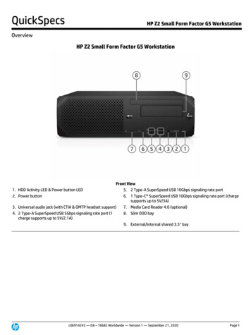
Removing and installing componentsThis section provides detailed information on how to remove or install the components from yourcomputer.Removing the cover1.Follow the procedure in Before Working Inside Your Computer.2.To remove the cover:a. Loosen the captive screws that secure the cover to the computer [1].b. Slide the cover toward the back of the computer [2].c. Lift the cover from the computer [3].Installing the cover1.Place the cover on the computer and slide the cover until it clicks into place.2.Tighten the captive screws to secure the cover to the computer.3.Follow the procedure in After Working Inside Your ComputerRemoving the front bezel1.Follow the procedure in Before Working Inside Your Computer.2.Remove the cover.3.To remove the front bezel:82
a. Lift the tabs to release the front bezel from the computer [1].b. Remove the front bezel from the computer [2].Installing the front bezel1.Insert the tabs on the bezel into the slots on the computer.2.Press the bezel until the tabs clicks into place.3.Install the cover.4.Follow the procedure in After Working Inside Your ComputerRemoving the fan duct1.Follow the procedure in Before Working Inside Your Computer.2.Remove the cover.3.To remove the fan duct:a. Holding the touch points, pull the fan duct bracket to release the fan duct [1].b. Lift the fan duct away from the computer [2].9
Installing the fan duct1.Align the slots on the fan duct, with the screws on the heat sink.2.Insert the fan duct until it clicks into place.3.Install the cover.4.Follow the procedure in After Working Inside Your Computer.Removing the memory module1.Follow the procedure in Before Working Inside Your Computer.2.Remove the cover.3.To remove the memory module:a. Press the memory module retention tabs on both sides of the memory module.b. Lift the memory module from the memory module connector on the system board.Installing the memory module1.Align the notch on the memory module with the tab on the memory module connector.2.Insert the memory module into the memory module socket.3.Press the memory module until the memory module retention tabs click into place.4.Install the cover.10
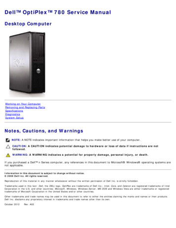
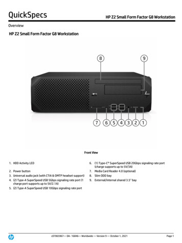
5.Follow the procedure in After Working Inside Your Computer.Removing the intrusion switch1.Follow the procedure in Before Working Inside Your Computer.2.Remove the:a. coverb. fan duct3.To remove the intrusion switch:a. Disconnect the intrusion switch cable from the connector on the system board [1][2].b. Slide the intrusion switch and lift it away from the computer [3].Installing the intrusion switch1.Insert the intrusion switch into the slot on the chassis.2.Connect the intrusion switch cable to the system board.3.Install the:a. fan ductb. cover4.Follow the procedure in After Working Inside Your Computer.Removing the expansion card1.Follow the procedure in Before Working Inside Your Computer.2.Remove the:a. coverb. fan duct3.To remove the expansion card:a. Pull the metal tab to open the expansion card latch [1].b. Pull the tab forward [2] and pull the expansion card from the connector on the computer [3].11
Installing the expansion card1.Insert the expansion card into the connector on the system board.2.Press the expansion card until it clicks into place.3.Close the expansion card latch and press it until it clicks into place.4.Install the:a. fan ductb. cover5.Follow the procedure in After Working Inside Your Computer.Removing the hard drive assembly1.Follow the procedure in Before Working Inside Your Computer.2.Remove the:a. coverb. fan duct3.Disconnect the data and power cables from the connectors on the hard drive assembly.12
4.To remove the hard drive assembly:a. Pull the hard drive release handle forward to release the hard drive bracket from the computer [1].b. Lift the hard drive assembly away from the computer [2].Removing the hard drive from the hard drive bracket1.Follow the procedure in Before Working Inside Your Computer.2.Remove the:a. coverb. bezelc. hard drive assembly3.To remove the hard drive bracket:a. Pull the hard drive bracket to release the hard drive [1].b. Lift the hard drive out of the hard drive bracket [2].13
Installing the hard drive into the hard drive bracket1.Insert the hard drive into the hard drive bracket until it clicks into place.2.Install the:a. hard drive assemblyb. bezelc. cover3.Follow the procedure in After Working Inside Your Computer.Installing the hard drive assembly1.Insert the hard drive assembly into the slot on the computer.2.Connect the power cable to the slot on the hard drive bracket.3.Install the:a. fan ductb. cover4.Follow the procedure in After Working Inside Your Computer.Removing the optical drive1.Follow the procedure in Before Working Inside Your Computer.2.Remove the:a. coverb. front bezelc. hard drive assembly3.To release the optical drive:a. Remove the hard drive connector cables from the optical drive latch [1].b. Slide the blue latch to the unlock position [2].14
4.To remove the optical drive:a. Holding the blue latch [1], lift the optical drive cage and disconnect the cables from the opticaldrive. [2]b. Lift the optical drive cage away from the computer [3].5.To remove the optical drive from the optical drive cage:a. Press the optical drive release latch [1] and slide the optical drive forward. [2]b. Remove the optical drive from the optical drive cage [3].Installing the optical drive1.Slide the optical drive into the optical drive cage.2.Align the tabs on the optical cage with the slots on the computer.15
3.Lower the optical drive cage into the computer and lock the latch.4.Connect the data and power cables to the optical drive.5.Install the:a. hard drive assemblyb. front bezelc. cover6.Follow the procedure in After Working Inside Your Computer.Removing the system fan1.Follow the procedure in Before Working Inside Your Computer.2.Remove the:a.b.c.d.3.coverfront bezelhard drive assemblyoptical driveTo remove the system fan:a. Disconnect the system fan cable from the system board [1].b. Slide the fan grommets toward the slot on the back wall [2].c. Lift the fan away from the computer. [3]Installing the system fan1.Place the system fan in the computer.2.Pass the grommets through the chassis and slide outward along the groove to secure it in place.3.Connect the system fan cable to the system board.4.Install the:a.b.c.d.5.16optical drivehard drive assemblyfront bezelcoverFollow the procedure in After Working Inside Your Computer.
Removing the heat sink assembly1.Follow the procedure in Before Working Inside Your Computer.2.Remove the:a.b.c.d.e.3.coverfront bezelfan ducthard drive assemblyoptical driveTo remove the heat sink assembly:a. Disconnect the heat sink cable from the system board. [1]b. Loosen the captive screws that secure the heat sink assembly and lift it away from the computer[2] [3].Installing the heat sink assembly1.Place the heat sink assembly onto the processor.2.Tighten the captive screws to secure the heat sink assembly to the system board.3.Connect the heat sink cable to the system board.4.Install the:a.b.c.d.e.5.fan ductoptical drivehard drive assemblyfront bezelcoverFollow the procedure in After Working Inside Your Computer.17
Removing the processor1.Follow the procedure in Before Working Inside Your Computer.2.Remove the:a.b.c.d.e.f.3.coverfront bezelhard drive assemblyoptical drivefan ductheat sinkTo remove the processor:a. Release the socket lever by pushing the lever down and out from under the tab on the processorshield [1].b. Lift the lever upward and lift the processor shield [2].c. Lift the processor out of the socket [3].Installing the processor1.Align the processor with the socket keys.2.Align the pin-1 indicator of the processor with the triangle on the socket.3.Place the processor on the socket such that the slots on the processor align with the socket keys.4.Close the processor shield by sliding it under the retention screw.5.Lower the socket lever and push it under the tab to lock it.6.Install the:a.b.c.d.e.f.7.heat sinkfan ductoptical drivehard drive assemblyfront bezelcoverFollow the procedure in After Working Inside Your Computer.Removing the VGA card1.Follow the procedure in Before Working Inside Your Computer.2.Remove the:18
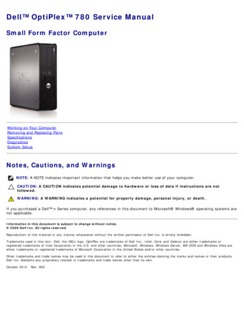
a. coverb. fan duct3.To remove the VGA card:a.b.c.d.Remove the screws that secure the VGA connector to the computer [1].Slide the VGA connector to release it from the computer [2].Remove the screw that secures the VGA card to the computer [3].Lift the VGA card using the handle to remove it from the computer [4].Installing the VGA card1.Align the VGA card with the screw holder on the system board.2.Tighten the screw to secure the VGA card to the system board.3.Insert the VGA connector into the slot at the back of the computer.4.Tighten the screws to secure the VGA connector to the computer.5.Install the:a. fan ductb. cover6.Follow the procedure in After Working Inside Your Computer.Removing the power supply unit (PSU)1.Follow the procedure in Before Working Inside Your Computer.2.Remove the:a.b.c.d.e.3.coverfront bezelhard drive assemblyoptical drivefan ductTo release the PSU:a. Disconnect the power cable from the system board [1] [2].b. Unroute the power cables from the retention clips on the chassis [3] [4].19
4.To remove the PSU:a. Disconnect the power cable from the system board [1] [2].b. Lift the cables away from the computer [3].c. Remove the screws that secure the PSU to the computer [4].5.20Press the blue release tab [1], slide the PSU and lift it away from the computer [2].
Installing the power supply unit (PSU)1.Insert the PSU in the chassis and slide it toward the back of the computer to secure it.2.Tighten the screws to secure the PSU to the back of the computer.3.Route the PSU cables through the retention clips.4.Connect the power cables to the system board.5.Install the:a.b.c.d.e.6.fan ductoptical drivehard drive assemblyfront bezelcoverFollow the procedure in After Working Inside Your Computer.Removing the power switch1.2.Follow the procedure in Before Working Inside Your Computer.Remove the:a.b.c.d.e.3.coverfront bezelhard drive assemblyoptical drivepower supply unitTo remove the power switch:a. Disconnect the power switch cable from the system board [1].b. Press the power switch retention tabs and remove it from the chassis [2] [3].21
Installing the power switch1.Slide the power switch module into the slot on the chassis until it clicks into place.2.Connect the power switch cable to the connector on the system board.3.Install the:a.b.c.d.e.4.power supply unitoptical drivehard drive assemblyfront bezelcoverFollow the procedure in After Working Inside Your Computer.Removing the SD card reader1.2.Follow the procedure in Before Working Inside Your Computer.Remove the:a.b.c.d.e.3.coverfront bezelhard drive assemblyoptical drivepower supply unitTo remove the SD card reader:a. Remove the power supply unit cables from the retention clips on the SD card reader enclosure[1].b. Remove the screws that secure the SD card reader assembly and lift it away from the computer[2] [3].22
Installing the SD card reader1.Place the SD card reader assembly on the chassis.2.Tighten the screws that secure the SD card reader to the computer.3.Route the power supply unit cables into the retention clips.4.Install the:a.b.c.d.e.5.power supply unitoptical drivehard drive assemblyfront bezelcoverFollow the procedure in After Working Inside Your Computer.Installing the optional SSD card1.Remove the:a. coverb. front bezel2.Peel the adhesive tape (blue) from the rubber.23
3.Place the rubber on the computer [1] and peel the adhesive tape (pink) from the rubber [2].4.To install the SSD card:a. Connect the SSD card to the connector on the system board [1].b. Tighten the screw to secure the SSD card to the system board [2].24
Removing the optional SSD card1.Follow the procedure in Before Working Inside Your Computer.2.Remove the: cover3. front bezelRemove the screw that secures the SSD card to the system board.4.Disconnect the SSD card from the connector on the system board.5.Remove the rubber from the system board.Removing the system board1.Follow the procedure in Before Working Inside Your Computer.2.Remove the:a.b.c.d.e.f.g.h.i.j.k.l.3.coverfan ductfront bezelmemory modulehard drive assemblyoptical driveexpansion cardoptional SSD cardSD card readerVGA connectorheat sinkprocessorTo remove the I/O panel:a. Remove the screw that secures the I/O panel to the chassis [1].b. Remove the I/O panel from the computer [2].25
4.Disconnect all the cables connected to the system board.5.To remove the system board:a. Remove the screws that secure the system board to the computer [1].b. Slide the system board toward the front of the computer and lift it from the computer [2].26
Installing the system board1.Hold the system board by its edges and angle it toward the back of the computer.2.Lower the system board into the computer until the connectors at the back of the system boardalign with the slots on the back wall of the computer, and the screw holes on the system board alignwith the standoffs on the computer.3.Tighten the screws that secure the system board to the computer.4.Connect the cables to the system board.5.Install the:a.b.c.d.e.f.g.h.i.j.k.l.VGA connectorSD card readeroptional SSD cardexpansion cardprocessorheat sinkoptical drivehard drive assemblymemory modulefront bezelfan ductcover6.Place the I/O panel on the chassis.7.Tighten the screws to secure the I/O panel to the chassis.8.Follow the procedure in After Working Inside Your Computer.27
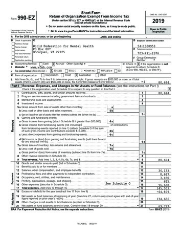
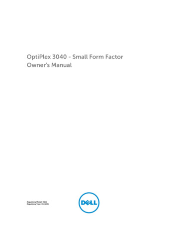
System board layout1.PCIex16 connector2.PCIex1 connector3.RJ-45/USB 2.0 connector4.USB 3.0 connector5.Keyboard MS connector (optional)6.DisplayPort connector7.HDMI connector8.Line-out connector9.CPU power connector10.Intrusion switch connector11.VGA daughter board connector12.Processor13.CPU fan connector14.Memory module connectors15.Power switch connector16.Media card reader connector (optional)17.System fan connector18.Hard drive activity LED19.Universal audio jack20.USB 2.0 connector21.USB 3.0 connector22.ATX power connector23.SATA2 connector24.Password clear jumper25.Service mode jumper26.Speaker connector27.SATA hard drive power cable connector28.Internal USB connector28
29.SATA connector31.Clear CMOS jumper30.Coin cell battery29
Troubleshooting your computer3You can troubleshoot your computer using indicators like diagnostic lights, beep codes, and errormessages during the operation of the computer.Diagnostic power LED codesTable 1. Diagnostic power LED codesPower LED light statusPossible causeTroubleshooting stepsOffThe computer is either turned off or is not receiving power or inHibernation mode. Steady/Blinking AmberComputer fails to complete POST or processor failure. Blinking White LightComputer is in sleep mode. Steady WhiteRemove and reinstall any cards.Remove and reinstall thegraphics card, if applicable.Ensure the power cable isconnected to the system boardand processor.Press the power button to bringthe computer out of the sleepmode.Ensure all power cables aresecurely connected to thesystem board.Ensure the main power cableand front panel cable areconnected to the system board.The computer is fully functional and If the computer is not responding,in the On state.do the following: 30Re-seat the power cable in thepower connector on the back ofthe computer and the electricaloutlet.If the computer is plugged into apower strip, ensure that thepower strip is plugged into anelectrical outlet and is turned on.Also, bypass power protectiondevices, power strips, and powerextension cables to verify thatthe computer turns on properly.Ensure the electrical outlet isworking by testing it withanother device, such as a lamp.Ensure the display is connectedand turned on.
Power LED light statusPossible causeTroubleshooting steps If the display is connected andturned on, listen for a beepcode.Diagnostic error messagesTable 2. Diagnostic error messagesError messagesDescriptionAUXILIARY DEVICE FAILUREThe touchpad or external mouse may be faulty. Foran external mouse, check the cable connection.Enable the Pointing Device option in the SystemSetup program.BAD COMMAND OR FILE NAMEEnsure that you have spelled the commandcorrectly, put spaces in the proper place, and usedthe correct path name.CACHE DISABLED DUE TO FAILUREThe primary cache internal to the microprocessorhas failed. Contact Dell.CD DRIVE CONTROLLER FAILUREThe optical drive does not respond to commandsfrom the computer.DATA ERRORThe hard drive cannot read the dat
3. To remove the intrusion switch: a. Disconnect the intrusion switch cable from the connector on the system board [1][2]. b. Slide the intrusion switch and lift it away from the computer [3]. Installing the intrusion switch 1. Insert the intrusion switch into the slot on the chassis. 2. Connect the intrusion switch cable to the system board. 3 .