Transcription
Micro-grooved Surface Topography Does Not Influence Fretting Corrosion ofTapers in THA: Classification and Retrieval AnalysisA ThesisSubmitted to the FacultyofDrexel UniversityByChristina Marie ArnholtIn partial fulfillment of the requirementsFor the degreeofMasters of Science in Biomedical EngineeringJune 2015i
Copy Rightii
AcknowledgementsFirst I would like to thank my mom, Cindy Arnholt for always being supportive andbelieving that I could accomplish anything. This wouldn’t have been possible without you.Additionally I would like to thank my boyfriend of 6 years, Chris Ousey for always beingsupportive and proud of me.To Dr. Steven Kurtz I would like to say thank you for taking a chance on me. Whenwe first met I had done nothing notable and had no proof of what I could do. Knowingthat someone with as much experience believed in me gave me the strength to push myselffar beyond what I dreamed possible. Your far sighted style of thinking has given me a betterapproach to work and life. I admire and hope to be like you someday.To Daniel Macdonald thank you for being a good friend and mentor. Thank you foranswering the phone in the middle of the night and talking me off the ledge. Thank you forproof reading all of my papers and being a sounding board to bounce ideas off of. I don’tthink this would have been possible without you.To Michael Beeman thank you for being the other neurotic person in the lab. Thankyou for booking all of my flights, for answering all of my silly questions and for handling allof the paper work. I will miss you.To Richard Underwood thank you for being a good friend and mentor. Thank youfor joking with me, fighting with me and pushing me to be better. I respect your opinionseven if I don’t always say it. I look forward to working with you in the future.iii
To Drexel Implant research center family I love you guys. Thank you for dealingwith me when I’m half asleep and talking incessantly, for making fun of me for drinking toomuch coffee and for always listening. I will always feel like I was a part of something greatbecause of you guys.iv
Table of ContentsList of Figures .viiiList of Tables . xiAbstract . xii1. Problem Statement . 12. Specific Aims . 31. Develop a method to characterize a broad range of machined smooth stems andintentionally micro-grooved stems. . 32. Using multivariate analysis of covariance to determine the associated factors withfretting corrosion. . 33. Introduction and Background . 53.1. Total Hip Arthroplasty . 53.2. Tapers . 63.2.1. Introduction of Tapers . 63.2.2. History of Tapers . 93.3. Clinical Implications .103.4. Corrosion .113.4.1. Background .11v
3.4.2. Mechanically Assisted Crevice Corrosion .123.4.3. Semi Quantitative Scoring Method .143.4.2. Taper Corrosion Implant Factors .153.6. Surface Topography .183.6.1 Introduction of Surface Topography .183.6.2. Current Analysis of Surface Topography in THA.194. Aim 1: A Classification System for Surface Topography .224.1. Hypothesis .224.3. Design Block Diagram .224.4. Materials and Methods .234.4.1. Implant Information .234.4.2. Microscopy and Visual Inspection .244.4.3. White Light Interferometry.244.4.4. Stylus Profilometer .244.4.5. Final Design Validations .254.5. Results .265. Aim 2: Patient and Implant Factors Associated with Fretting Corrosion .365.1. Hypothesis .365.2.1. Clinical Information .365.2.2. Design Variables .37vi
5.2.3. Fretting and Corrosion Evaluation .385.2.4. Statistical Analysis.405.3. Results .407. Discussion and Conclusion .45References .50vii
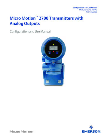
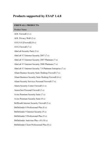
List of FiguresFigure 1. Image of total hip arthroplasty components used in a standard procedure . 6Figure 2. Description of Morse Taper Design and terminology . 7Figure 3. Diagram of THA head neck taper junction . 8Figure 4. Description of crevice corrosion reaction with stagnant fluid, reactive species andreleased metallic ions .12Figure 5. Example of imprinting within femoral head of a micro-grooved stem surface .18Figure 6. Three different components photographed using Nikon D80 (Chiyoda Tokyo) and3D digital microscope (Keyence VHX-5000 series Digital Microscope). Although figure C isclearly micro-grooved, A and B are subjectively classified using this method .28Figure 7. Figure 4.5.2. Two different components analyzed using white light interferometry.The components are clearly distinguishable between smooth and micro-grooved. Figure Ahas a Wmax value of 1.73 um, while figure B has a value of 11.30. Although the filtersutilized during data collection made this method not appropriate .29Figure 8. Plot of PA values collected from 398 femoral stem components using a stylusprofilometer. It is clear that there is no separation describing two different surfacetopographies. .30Figure 9. Plot of PA values for different geometries .30Figure 10. Typical surface profiles (Left) and micrographs (Right) of A) un-patternedsmooth, B) low amplitude and wavelength patterned smooth surface and C) micro-groovesfrom femoral neck taper surfaces. .32viii
Figure 11. Amplitude values of known smooth and micro-grooved components. .33Figure 12. Wavelength values of known smooth and micro-grooved components .34Figure 13. ROC curve representing different cutoff values of amplitude (A) and wavelength(W) .34Figure 14. Reported area under the curve values and standard errors from ROC curveanalysis .34Figure 15. Known micro-grooved and smooth wavelength vs. amplitude plot with finalclassification system marked with black line. .35Figure 16. Classification of 398 THA components.35Figure 17. Design variables measured from the femoral stem. .38Figure 18. Exemplar components for each of the scores in the four point scoring method. 39Figure 19. Figure 5.3.1. Stacked bar plot of the fretting corrosion damage score of femoralheads with respect to surface topography classification. From the plots it is observed that thesmooth taper surface topography has a higher damage score potentially due to confoundedfactors such as engagement length, implantation time and flexural rigidity .41Figure 20. An example of a micro-grooved surface topography with a fretting corrosiondamage score of 4 (A) and a femoral head that has an imprinted corrosion pattern (B). .42Figure 21. Distribution of implantation time by fretting corrosion damage scores of thefemoral head taper. A significant positive correlation (p 0.0001) was observed betweenimplantation time and fretting corrosion score of the femoral head in multivariate analysis ofvariance. .42Figure 22. Distribution of apparent engagement length by fretting corrosion damage scoresof the femoral head taper. A significant negative correlation (p 0.0001) was observedix
between the apparent engagement length and fretting corrosion score of the femoral head inmultivariate analysis of variance. .43Figure 23. Distribution of flexural rigidity of the stem trunnion by fretting corrosion damagescores of the femoral head taper. A significant negative correlation (p 0.008) was observedbetween the flexural rigidity and fretting corrosion score of the femoral head in multivariateanalysis of variance. .44x
List of TablesTable 1. Scoring criteria for semi quantitative scoring method .15Table 2. Design matrix quantifying compliance of different measurement methods with thedesign specifications listed in section 4.2. Maximum compliance was described with a scoreof 5 and minimum compliance was described with a score of 0 .27xi
AbstractMicro-grooved Surface Topography Does Not Influence Fretting Corrosion ofTapers in THA: Classification and Retrieval AnalysisChristina Marie ArnholtDr. Steven Kurtz, Ph.D.Surface topography of the femoral stem trunnion has been suggested as a factor infretting corrosion of the taper interface in total hip arthroplasty (THA). The purpose of thisstudy was to identify if femoral stem taper morphology was correlated with taper frettingand corrosion. This was accomplished by first developing a method to characterize a broadrange of machined smooth stems and intentionally micro-grooved stems. Throughmultivariate analysis of covariance, different factors were tested for correlation with frettingcorrosion. Finally a matched cohort was designed controlling all related factors to deduceweather surface topography was related with fretting corrosion.From a multi-institutional retrieval collection of over 3,000 THAs, 398 stems pairedwith CoCr (ASTM-F75) alloy heads were collected as part of a multi-center, IRB-approvedretrieval program. Stems were fabricated from CoCr (ASTM-F75) or Titanium (Ti6V4Al)alloys and were used in metal on polyethylene (M-PE) bearing total hip devices. Other stem,femoral head alloys, and different bearing combinations were removed from this study. Thedevices had a single location of modularity at the head neck junction.In order to classify the surface topography into two groups visual inspection,microscopy, white light interferometer (Zygo New View 5000) and a stylus profilometerxii
(Talyrond 585, Taylor Hobson, UK) were used. The final method employed a stylusprofilometer with which linear profiles were measured using a diamond tip stylus capturing a10 mm line trace. Commercial software (Ultra, Taylor Hobson, UK) was used to analyze a 1mm representative as-manufactured region. Three parameters were calculated from theprofiles: average surface roughness, amplitude and wavelength of micro-grooves (if any).Surface observations led to a classification system in which a surface had to contain aperiodic pattern, a wavelength 140 μm and an amplitude of 5 μm to be consideredmicro-grooved. Fifty percent (200/398) of the femoral stem taper surfaces were classified assmooth tapered stems. The remaining 50% (198/398) femoral stem taper surfaces wereclassified as micro-grooved tapered stems.A semi-quantitative scoring method was used to classify the stem-head pairs intofour groups based on quantity of damage on the female and male taper surfaces [1, 2]. Forthis study the femoral head taper was characterized. With this scoring system, a score of 1 isassigned when the damage is considered minimal and corresponds to fretting damage occurringon less than 10% of the surface with no pronounced evidence of corrosion. A score of a 2indicates mild damage where more than 10% of the surface has fretting damage or there iscorrosion attack confined to small areas. A score of a 3 reflects moderate damage where morethan 30% of the surface has fretting damage or localized corrosion attack. A score of 4corresponds to severe damage over the majority of the taper ( 50%) with abundant corrosiondebris. The femoral head taper was independently evaluated by three trained investigators(C.A., G.B.H, and D.W.M.). Any differences between investigators damage scores wereresolved in a conference, resulting in a final damage score for both the femoral head andstem.xiii
Using multivariate analysis of covariance we found implantation time (p 0.0001),apparent engagement length (p 0.0001), flexural rigidity (p 0.008) and head size (p 0.01)were significant factors in fretting corrosion head damage scores. Surface topography (i.e.smooth or micro-grooved, p 0.78), surface wavelength (p 0.60), and surface amplitude(p 0.23) were not associated with femoral head fretting corrosion damage score.Overall, the results of this study do not support trunnion surface morphology as acontributing factor to fretting and corrosion damage at the modular head-neck interface.This was deduced through an initial classification system, followed by statistical analysis,which showed correlated factors and finally a controlled matched cohort that showed nocorrelation between surface topography and fretting corrosion. This study was limited bythe use of a semi quantitative scoring method. Future work would include the use ofquantified volume of metal released from each cohort.xiv
xv
1. Problem StatementTotal hip arthroplasty is a successful surgery that allows increased patientfunctionality and loss of pain. Although it is a successful surgery, within the United Statesthe rates of both primary and revision surgeries have increased [3]. Because of this,researchers have been trying to identify implant and patient factors associated with failure.One failure mode involves mechanically assisted taper corrosion, which has previously beenlinked to a multitude of factors including femoral head size, flexural rigidity and implantationtime [2].Recently, surface topography has been suggested as a factor in fretting corrosion,because of the recent observation of “micro-grooved” surface topography [4-7]. It isbelieved that these surfaces were created to limit the stress concentration created from amismatch of cone geometry tolerances specifically for ceramic heads [8]. These surfaceshave been observed as large and smaller grooves with varying wavelengths and amplitudesdependent on manufacturer and design [5, 7]. Femoral stems with these machined surfacescan be paired with both ceramic and femoral heads [7]. It has been observed in severalstudies that “imprinting” from the stem surface topography can occur on the inside of metalfemoral heads [8-12]. Imprinting is explained as in vivo corrosion damage [8, 11].Currently, a standard method for classifying surface morphology does not exist.Previous research has suggested using a classification system consisting of two groups:threaded and non-threaded [13]. Additional studies have looked at the effects of surfacetopography on fretting corrosion, however these studies are limited by observing the femoralstem [14] which has been shown to not be the main cause of material loss. Other studies are1
limited by number of manufacturers leading to confounded factors such as apparentengagement length and surface topography [15, 16].In order to accurately distinguish if there is a correlation between surface topographyand fretting corrosion, an adequately sized cohort classified for surface topography withcontrolled implant, patient and clinical factors is needed.2
2. Specific Aims1. Develop a method to characterize a broad range of machined smooth stems andintentionally micro-grooved stems.To understand the potential impact of manufactured micro-grooves on the frettingcorrosion behavior of modular total hip arthroplasty (THA) components, aclassification system is needed to identify which femoral neck tapers have microgrooves. Additionally large variations in design dimensions exist betweenmanufactures, making it necessary to create a method of classification for all designsand manufactures to deducing the “type” of trunnion surface. This methodology isnecessary for creating a standardization and comparability between studies of THAtrunnion topography. Developing a highly repeatable classification method wascrucial to the success of this study.2. Using multivariate analysis of covariance to determine the associated factors with frettingcorrosion.The use of step-forward multivariate linear modeling utilizing an ordinal logistic fitallowed for the analysis of ordinal fretting corrosion scores. This was used toevaluate the role of surface morphology in the context of other variables known toinfluence corrosion damage. Through this statistical analysis, it will be possible to3
deduce whether fretting corrosion is influenced by surface morphology and othervariables.4
3. Introduction and Background3.1. Total Hip ArthroplastyThe use of modern total hip arthroplasty (THA) to combat patient ailments such asosteoarthritis, osteonecrosis, dysplasia and inflammatory arthritis began between the 1960sand 1970s when Sr. John Charnley introduced the Charnley hip [3, 17]. Surgery is commonlyindicated for chronic pain and osteoarthritis. This approach is considered a secondarysolution to less invasive techniques such as activity modification, weight loss or even intraarticular injections [3]. This surgery is clinically successful with reports of survivorship over93% survivorship after eight years [18]. The surgery accounts for a 2.7 billion dollar annualburden with 284,000 primary surgeries and 45,000 revision surgeries each year [19].THA is a surgery in which an artificial hip is used to replace a damaged native hipstructure. The native hip is composed of a ball and socket joint. The femoral head is locatedat the superior aspect of the femur and its articulating surface is covered with cartilage. Thisfits into a concave cavity also covered with cartilage called the acetabulum. During surgerythe femoral head is removed and the femoral shaft is reamed creating a canal, in which thefemoral stem is implanted [17]. The acetabulum is commonly replaced with a metal cupcalled the acetabular shell and an ultra-high molecular weight polyethylene (UHMWPE) liner[17], Figure 1.5
Figure 1. Image of total hip arthroplasty components used in a standard procedureA single modular taper junction is incorporated in most THA components betweenthe femoral head and stem. Modularity allows for interchangeability of femoral heads[20],and an easier insertion of the femoral stem[20, 21]. Modularity also allows the combinationof different materials and different sized femoral heads, which can be decided on a perpatient basis [21]. Additional modular junctions have been incorporated into modern THAdesigns to assist with the femoral neck angle and limb length discrepancies [22], while theseallow for a more successful surgery in the short term, they may result in increased corrosionin the long term [1].3.2. Tapers3.2.1. Introduction of TapersThe Morse taper, invented in 1864 by Stephen A. Morse, was originally used toconnect rotating machinery components. [23]. Machinery handbooks define this style oftaper as “self-handling”, and indicate its common uses such as drilling and machine lathing6
[24]. The term self-handling means that the taper can be impacted and maintain the juncturewithout any additional design features such as locking pins. This strong association originatesfrom the friction created between mating components due to close contact resulting fromsmaller taper angle [25]. In contrast, self-releasing styled tapers, which have a much largertaper angle and decreased contact between mating surfaces require an additional lockingmechanism to secure the fit. Through the control of length and diameters with a constanttapering slope, machinists are able to control the amount of contact a taper has with itsmating surface. Machining tapers are described by taper per foot, which fluctuates accordingto the taper number [25]. For example a 1 foot taper with a 1/3 inch diameter on one endand 2/3 inch diameter on the other end, would be described as being tapered 1/3 inch perfoot, Figure 2.Figure 2. Description of Morse Taper Design and terminology7
The use of taper junction became widely used in orthopedics with the introductionof ceramic femoral heads [23]. The original method for attaching a ceramic femoral head toa metallic stem was to glue and then screw the components together which caused ceramicfailure through fracture [23]. In 1974 Professor Mittelmeier used the Morse taper to facilitatethe connection, decreasing the rate of head fractures [23]. The term Morse taper is looselyused to describe the cone shape and self-handling capability of orthopedic tapers. However,general naming techniques such as 11/13 or 12/14 describe the small and large diameters ofTHA tapers. These tapers are used today in orthopedics (total knee arthroplasty, total hiparthroplasty, and shoulder arthroplasty), dentistry, and still in machining tools. A taperconsists of a protruding cone (male component) fitting into a tapered concave shape (femalecomponent). The two components are assembled intraoperatively. This process iscommonly called impaction, in which a hammer is used to secure the femoral head onto thefemoral stem, Figure 3.Figure 3. Diagram of THA head neck taper junction8
3.2.2. History of TapersIn the 1990s femoral tapers were used throughout THA in multiple bearingcombinations such as metal on polyethylene and metal on metal. Taper corrosion was notedat the head neck junction and attributed to particle generation, implant fracture and mixedalloys [20, 22, 26-29]. The use of taper connections was continued however, because it wasdetermined that the problems originated from poorly designed components and werepotentially not the cause of the failures in THA [30].In the 2000s large head metal on metal devices were widely used in THA [31]. Thesedevices were used because they had lower rates of dislocation and the metallic bearing waspredicted to have lower wear. However, the clinical experience differed. These systems hadreported taper fretting corrosion resulting in metallic debris release and biological reactions[31-35]. It was speculated that the larger head size allowed for increased torque at taper andbearing surfaces leading to increased wear [16].In the 2010s metal on metal devices continued to have debris release leading tobiological reactions [32, 36, 37]. Metal on polyethylene bearing couples exhibited blackenedtaper trunnions and elicited reactions to metallic debris similar to metal on metal devices [38,39]. These findings supported future research into other implant and patient factors thatmay be associated with fretting corrosion at the head neck taper junction.9
3.3. Clinical ImplicationsAs previously stated, fretting corrosion at the head neck junction has the possibilityof releasing metallic debris and corrosion byproducts. It is important to note that the metalrelease is not biologically inert. The size of metal particles has been associated with the typeof response elicited by metallic debris. Meyer et al. showed in vivo periprosthetic tissues havestored metal debris, eliciting a foreign body reaction and necrosis [36]. Through staining forCD68, a macrophage marker, and CD3, a lymphocyte marker there were sightings of bothreactions although the former was more abundant [36]. These findings were supported byHowie et al. who observed large numbers of macrophages around cementless metal on metaltissues while also noting minimal giant cell and lymphocyte activity [40]. Jacobs et al.reported the association of larger particles with giant cells or necrotic regions, while smallerparticles were found within macrophages. Mathiesen et al. reported patients withhypersensitivity experience a lymphocyte dominated reaction. Macrophages and giant cellswere also reported having phagocytized wear particles [29].The reaction is similar to a biological reaction to bacteria in which macrophages andother foreign body cells migrate to the metallic particles and phagocytize them [37, 41]. Thereaction differs because the metallic particles remain after the cells die, which then repeatsthe process escalating it to an elevated inflammatory response [41]. Cells are hypothesized todie due to toxic levels of cobalt after the removal of the passive layer within the lysosome ofthe cell [37]. An inflammatory mass can develop in response to the cytokines furthercontinued by the repeating of the process [37].10
Metal release can lead to adverse local tissue reactions [38, 42] which can manifest aspseudo tumors or hypersensitivity [43, 44]. Although it was originally observed in metal-onmetal bearing surfaces [36, 37], these phenomena can also occur in metal-on-polyethylenebearings [38, 39]. It is sometimes difficult to diagnose these reactions because patients oftencomplain about pain or recurrent instability [38, 42, 45]. Revision surgeries reveal blackdeposits at the head/neck junction associated with discoloration of the capsule,granulomatous mass or effusions [38, 42]. Before revision surgery this can be determinedusing serum ion levels observing for elevated cobalt levels and metal artifact reductionsequences (MARS) MRI observing for large masses [38, 42, 44, 46, 47]. Sectioning of theperiprosthetic tissue can also describe the reactions present around the device. Campbell etal. proposed an aseptic lymphocytic vasculitis-associated lesions (ALVAL) score whichdescribes examination of synovial lining integrity, inflamm
3D digital microscope (Keyence VHX-5000 series Digital Microscope). Although figure C is clearly micro-grooved, A and B are subjectively classified using this method .28 Figure 7. Figure 4.5.2. Two different components analyzed using white light interferometry. The components are clearly distinguishable between smooth and micro-grooved. .