Transcription
Bulletin No.:Service BulletinDate:PI1354IFebruary, 2019PRELIMINARY INFORMATIONSubject:Information on Vibration Analysis and DiagnosticModels:2014 Chevrolet Silverado 15002015-2018 Chevrolet Silverado 15002019 Chevrolet Silverado LD *2014 GMC Sierra 15002015-2018 GMC Sierra 15002019 GMC Sierra Limited *EXCLUDES HD Trucks*Built at Oshawa Assembly Plant (11th VIN position “1”) Attention:This PI also applies to any of theabove models that may be North America Export to Middle East, Israel, Chile, Peru and Thailandvehicles.This PI has been revised to add the 2019 Model Year, and include Vibration DiagnosticWorksheet instructions. Please discard PI1354H.Training AvailableUS CoursewareCourseDelivery PlatformCourse DescriptionLength13042.14D1-R2Virtual Classroom Training (VCT)Noise, Vibration and Harshness (NVH)11.5 hrs13042.14D2-R2Virtual Classroom Training (VCT)Noise, Vibration and Harshness (NVH)2.0 hrs13042.14H-R2Hands-On Training (est. avl. December 2014)Noise, Vibration and Harshness (NVH)8.0 hrs13042.14WWeb-Based TrainingNoise, Vibration and Harshness (NVH)2.0 hrs13042.13VVideo On Demand (VOD)PicoScope Noise, Vibration, andHarshness Diagnostics Overview15:05minutesGMCC Courseware13042.14WWeb-Based TrainingNoise, Vibration and Harness—13042.05D1Virtual Classroom Training (VCT)Noise Vibration & Harshness - Session 1—13042.05D2Virtual Classroom Training (VCT)Noise Vibration & Harshness - Session 2—13025.16HHands-On TrainingVibration Diagnosis (2 day classroomtraining)—13042.13VVideo On Demand (VOD)PicoScope Noise, Vibration, andHarshness Diagnostics Overview - VOD—Condition/ConcernSome customers may comment about a vibration at speeds of 56-72 km/h (35-45 mph) or 96-120 km/h (60-70 mph),which can be felt in either the seat or steering wheel.The purpose of this bulletin is to outline the recommendations and procedures for diagnosing and repairingvibrations caused by wheel and tire, axle components and/or propeller shafts.
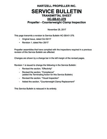
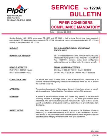
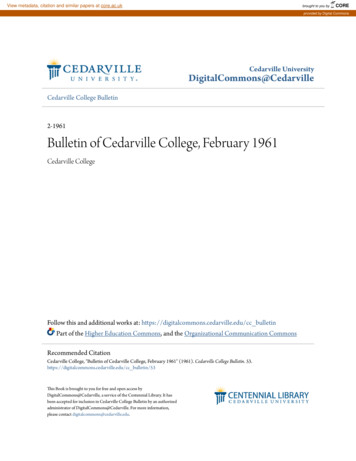
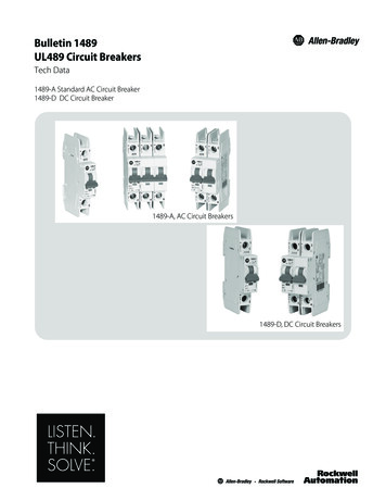
Recommendation/InstructionsImportant: The first step in determining the cause of the vibration is a test drive with the appropriate diagnosticequipment installed on the vehicle. If the correct tools and procedures are not followed, an incorrect diagnosis willresult.Full Size Truck Vibration Analysis:40021931. Inspect the truck for any aftermarket equipment installations. For example: non factory tires, wheels and/or liftkits or leveling kits – shims (1) installed as shown above. Aftermarket equipment does include running boards,bug deflectors, and window shades, etc. Remove any aftermarket that might cause vibration transmissionpaths.2. Mark each tire valve stems location on the tire. This will be utilized to check for tire slippage on the rim.40022063. Using a Pico Oscilloscope Diagnostic Kit, mount the PicoScope vibration sensor on one of the two locationsshown above.Note: Only the use of the Pico Oscilloscope Diagnostic Kit with NVH should be utilized, available from GM Dealerequipment (P/N 733–CH-51450). Previous vibrations tools are NOT recommended due to the types and frequenciesproducing these vibrations. Seat Vibration – mount the sensor to the front right corner of the driver’s seat bracket (1). Steering Wheel Vibration – mount the sensor to the steering wheel bracket (2) under dash.Note: In some cases, moving the sensor from a vertical position to a horizontal position may indicate higheramplitude and may be beneficial to help in diagnosis.
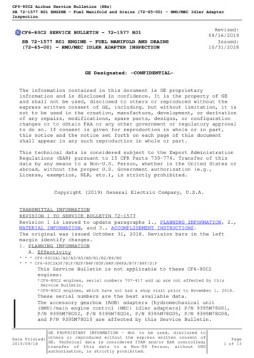
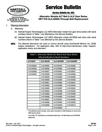
40022124. This step should be only be used if the vibration can be felt while running the vehicle on the rack. Mount thesensor on the steering shaft (1), under the hood as illustrated above.5. Measure the vibration. Typically trucks should be driven in M5 for 6 speed applications and M7 for 8 speedapplications to keep the engine from switching in and out of active fuel management (AFM).Note: At the bottom of this bulletin is a required Vibration Diagnostic Worksheet that MUST be completedand is required for the claim payment. Vibration Diagnostic must be retained by the dealership. Thisworksheet is required to be filled out before calling TAC.6. After the road test, verify that the tires have not slipped on the rim (step #2). If slippage has been found, correctthe condition prior to any other repair. Refer to the latest version of Corporate Bulletin Number 12-03-10-001:Vibration Shortly After Tires are Mounted/Preventing Vibration from Wheel Slip (Tire Sliding on Wheel).7. Once the condition has been duplicated on a test drive and the vibration readings have been recorded, bring thevehicle back into the shop and test the vehicle on four jack stands or a suitable hoist. The hoist must support thesuspension at the same trim heights as the vehicle would normally sit on the road.8. With the vehicle properly supported, bring the speed up to the complaint speed and verify that the previouslyrecorded vibration data matches current vibration data being displayed.9. The test should be performed in both 2 wheel drive and 4 wheel drive, if equipped. If vibration can be duplicatedon the rack, the test should be performed a second time with the wheels and tire assemblies removed from thevehicle and the wheel nuts installed to retain the brake discs and/or brake drums. If the vibration has beeneliminated with the wheel and tire assemblies removed, focus on the wheel and tire assemblies as the source ofthe vibration. If the vibration is still present, focus on the vehicle driveline as the source of the vibration.Additional Notes for Testing Phasing is typical on these trucks. Test drives should include many turns that can prevent phasing. Same test should be conducted after dealer correction to ensure vibration is eliminated throughout the entiretest repair phase.Use the chart below to determine which type of vibration the truck has and what repair procedure should be utilized.Type of VibrationGo to Condition1st Order Tire11st Order Prop Shaft22nd Order Prop Shaft33rd Order Tire Combined with 1st Order Prop4Vibration Felt in 4 cylinder mode (AFM) –V6 Engine Only5Vibration Felt at Idle Only6**For rough idle and/or vibration at idle in gear – 17–NA-166: Rough Idle.*For vibration related to AFM in 4 cylinder mode – refer to PIP5228: VibrationDuring Active Fuel Management V4 Mode Operation 1200–1400 Engine RPM.
Important: Prior to any Road Force Balancing done with the Hunter 9700, please make sure that the wheelassemblies pass the centering test, which is performed using the Hunter 9700 machine.Condition 1: 1st Order Tire Suggestions (Freq 11-14 hz at 60 mph or 97 km/h)MeasurementsRefer to Bulletin Number 17-NA-170: Information on Hunter Road Force Balancer.1. Remove the tire and wheel assemblies from the vehicle and perform the Road Force Variation (RFV)measurement.Important: Prior to taking any measurements, the assemblies MUST all pass a center check.2. Document the before and after Road Force Variation (RFV) numbers on the vibration worksheet located at theend of this bulletin.Road Force SpecificationsP-Metric tires on passenger cars15 lbs (6.8 kg) or lessP-Metric tires on light trucks15 lbs (6.8 kg) or lessLT - tires on light trucks15 lbs (6.8 kg) or lessNote: These numbers are lower than what is currently published in service information as some vehicles react toparts that are near the high limit. These numbers SHOULD NOT be used if you do not have a tire speed relateddisturbance.Repair: For any assembly that has an out of balance condition (greater than 0.25 oz), remove the weights and correctthe condition utilizing normal balancing techniques. For any assembly having Radial Force Variation (RFV) measurements beyond the specification above, shouldbe corrected utilizing the Hunter 180 Match Mount Process (See Hunter 180 Match Mount process below) priorto tire replacement. If this does not bring the assembly within specification, the tire should be replaced. Theexisting vectoring process cannot be utilized on Full size truck rims (except steel wheels) due to the removal ofthe out-board flange on the wheel which was utilized for the outboard rim runout measurement. Without thissurface, an inaccurate rim runout measurement would exist and negatively affect the vectoring calculation.Additional Notes on Balancing: Always perform a centering check. The Hunter Balancer/Road Force Balancer should not be set to “Smart Weight.” All tires need to be balanced under 0.25 oz (both static and dynamic). In many cases, it may be helpful to addweight to only one plane at a time. When using the Hunter – Balancer/Road Force Balancer, removal and remounting to the tire balancer shouldbe performed to re-check balance and verify that results are repeatable to 0.25 oz or less. Anytime a tire is removed from the wheel, the bare wheel should be mounted back on the vehicle and a runoutcheck be performed on-vehicle. This process not only checks the wheel but also all mounting surfaces andsuspension components that may effect runout.Important: When replacing tires, the road force should be checked before a test drive and after a test drive (min of10-15 miles or 16-24 km). Road force on new tires will change dramatically after being warmed up (as much as a20 lb reduction). After the test drive, the tire’s road force should be checked. If acceptable RFV cannot be achieved,first try vectoring the tire on the rim before an alternate tire is utilized. Also refer to the Information in the latestversion of Corporate Bulletin Number 13-03-10-002: Diagnostic Tips for Difficult to Resolve Tire/Wheel VibrationConcerns. Some more information is needed on how to check the assemblies for 2nd, 3rd, and 4th order RFV.Hunter 180 Match Mount ProcessGM passenger cars have had some limited flangeless wheel applications in the past, but starting with the launch ofthe 2014 Light Duty Pickup, several new Flangeless wheels were introduced. Flangeless refers to the outboardflange of the wheel where previously a clip-on weight would attach. The new wheels do not have a machined flangefor the Hunter Run-out Arm/Wheel to ride on. The previous process for tire and wheel assemblies that had high RoadForce, was using the tire Force Matching process. This process requires the use of the Runout Measurement armson the Hunter Road Force balancer. Without having this machined area, there is not a place for the Runout roller tomeasure. The Generation 3 and 4 RoadForce balancers have an alternate process called the 180 Match mount. OnGen IV machines this procedure can be found under RoadForce - Procedures - 180 Matching (or by selecting MatchMount without Rim Runout after initial RoadForce measurement).This process does not use the Runout Arms and instead utilizes the Load Roller to optimize Road Force. While thisprocess requires that the tire may need to be rotated up to 3 times on the rim to obtain the lowest Road Forcenumber, it is the only way for the technician to match mount these wheel and tire assemblies reliably.
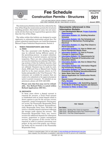
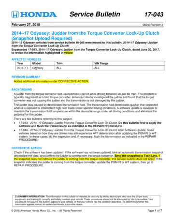
For more information on the 180 Matching process, please review the following Hunter Video that outlines theprocess. https://youtu.be/nswttgUKstkReplace Steering BushingsDouble Cab and Crew Cab Models Only built prior to:Silao – 11/3/16Ft Wayne – 10/25/16Flint – 9/30/16For Reg Cabs, see Replace Rear Cab Mounts belowImportant: The following procedure should only be used after all tire issues have been corrected. Installation ofrevised steering bushing will have little to no effect on trucks that still have tire conditions. The T1 vibration must bereduced to under 20-25mg’s for these bushings to be effective.4743660A revised steering bushing (2) has been released to address customer vibration concerns. After various testing andmeasurement of the T1 vibration, a vibration path from the tie rods steering rack steeringbushings frame Body Mount Cabin Floor Seat has been identified. To help isolate the steering rack (1), arevised hydraulic bushing has been released and tuned to the T1 frequency. The new steering bushing dampensminor T1 vibrations. This is the reason that the causal part (normally the Tire/Wheel Assembly) must be correctedfirst. If the T1 vibration is over 20-25m/g’s, the bushings will have little to no effect.4728689For vehicles with T1 vibrations under 20-25m/g’s, replace steering bushing per parts catalogue. Utilize SI procedure“Steering Gear Mount Bushing Replacement” for replacement of the steering bushings.
Warning: Care must be taken to not damage the EPS Motor electrical connectors or gear replacement maybe required.DescriptionPart NumberQtySteering Gear Bushing (CK10006 (SUV), K15743,K15543-NHT, K15753-NHT)842349602Steering Gear Bushing (C1004353, K15753 & NHT,K15543 & NHT842349592Replace Rear Cab Mounts - Regular Cab Models Built Prior To November 28, 2017A revised Rear Cab Mount has been released to address customer vibration concerns. After various testing andmeasurement of the T1 vibration, a vibration path from the tie rods steering rack steeringbushings frame Body Mount Cabin Floor Seat has been identified. To help isolate the cab, a revised CabMount has been released and tuned to the T1 frequency. The new cab mount dampens minor T1 vibrations. This isthe reason that the causal part (normally the Tire/Wheel Assembly) must be corrected first. If the T1 vibration is over20-25m/g’s, the cab mount will have little to no effect.Correction: Replace Rear Cab Mount with Revised part number.4816998DescriptionPart NumberQtyCUSHION, BODY MT UPR LOCATION #2843323912Condition 2: 1st Order Prop Shaft (Freq 38-44 hz at 60 mph or 97 km/h)Perform Propeller Shaft Runout Measurement (Refer to the SI Document ID# 2084709)Specification0.050”*Actual Measurement*For Best Result, the maximum runout should be under 0.20.” If over,then replace the driveshaft.Note: These numbers are lower than what is currently published in service information as some vehicles react toparts that are near the high limit. These numbers SHOULD NOT be used if you do not have a propeller shaft speedrelated disturbance.
Check Pinion Flange Runout MeasurementSpecial Tools: GE-7872 Magnetic Base Dial Indicator Set, equivalent GE-8001 Dial Indicator Set, or equivalentFor equivalent regional tools, refer to the Special Tools and Equipment in SI.Note: 1.2.3.4.This measurement procedure is intended to measure propeller shaft runout for prop shaft systems with 2 or 3U-joints only. This is not for prop systems with only 1 U-joint, or with only constant velocity (CV) joints, and/orcoupler assemblies.When measuring runout of propeller shafts, do not include fluctuations on the dial indicator due to welds orsurface irregularities.Raise and support the vehicle with the wheels free to rotate. Refer to the Lifting and Jacking the Vehicle in SI.Place the transmission is NEUTRAL.Clean the circumference of the propeller shaft of any debris and/or undercoating along the rear of the shaft,where contact of the dial indicator will make to the propeller shaft.Inspect the propeller shaft for dents, damage, and/or missing weights. Any propeller shaft this is dented ordamaged requires replacement.7345215. Mount the GE-7872 Magnetic Base Dial Indicator Set, or equivalent, or the GE-8001 Dial Indicator Set, orequivalent, to the vehicle underbody or to a service stand positioned just clear of the U-joint yoke weld on theprop shaft.6. Rotate the drive pinion axle flange, torque tube input flange, transmission output, or transfer case output flangeby hand while take runout measurements of the prop shaft. The prop shaft will rotate more easily in onedirection than in the other. If necessary, the tire and wheel assemblies and even the brake caliper assembliescan be positioned and supported aside, or the brake drums can be removed from the drive axle to provide axleto provide easier rotation of the prop shaft.7. Measure and mark the high spot of the propeller shaft. Mark the location of the propeller shaft to flange.8. Rotate the propeller shaft 180 degrees from its original position on the flange.9. Perform step six again.10. If the high spot of the propeller shaft is in the same location as marked in the previous step and themeasurement exceeds the maximum prop shaft runout specified, the prop shaft requires replacement beforeproceeding.Note: This measurement is focused on pinion flange runout, it is NOT a complete measurement of the prop shaftrunout. To fully measure prop shaft runout, measurements must be taken at the front and middle of each prop shaftsegments.11. If the high spot is in a different location, the runout is in the pinion flange or pinion. If this exceeds the maximumallowable runout for the pinion flange, the source of the runout (usually the flange or the pinion itself) must befound.
Perform Balance Measurement using “Adjustment Procedure Using Oscilloscope” (PicoScope) (Refer to theSI Document ID# 3753593)Specification10 g-cmActual MeasurementFor vehicles that are out of balance, perform a system balance. Using the two hose clamp method, the best drivelinebalance results are obtained under 10 g-cm.Suggestions:1. Perform Runout Measurement.2. Disassembly/reassembly rear yoke joint – checks for shift in U-joint.3. Evaluation Drive.4. Perform Runout Measurement.5. Index 180.6. Evaluation Drive.7. Perform Runout Measurement.8. Evaluation Drive.9. Balance Shaft with PicoScope.Diagnostic Aid:4002784 Inspect the propeller shaft for dents or damage. There have been many cases of dented propeller shafts.For 4WD Trucks, remove the rear propeller shaft, seal output shaft and drive the vehicle in 4WD. If the vibrationis gone, the rear prop shaft could be the problem.For vehicles with a 3:08 with a one-piece steel shaft, this can be replaced with a one-piece aluminum one thatis utilized on all 3:42 and 3:73 ratios (K15543 and K15753 Models only).PIP5140: Low Speed Vibration 30-35 mph (48-56 km/h).Inspect the transmission output shaft bushing for irregular wear.Condition 3: 2nd Order Prop Shaft (Normally a launch shudder or left under hard acceleration)Note: Vehicle rear suspension must be properly supported during the Driveline Angle measurement process inorder to record true Driveline Angle measurements.Check Driveline Angles (Refer to SI Document ID# 2084724)Suggestion:1. Check Angle.2. Disassembly/reassembly rear yoke – check for shift in U-joint.
3. Check Angle.4. Evaluation Drive.MeasurementYoke to ShaftFront Shaft to Center SupportBearing (if equip)Shaft to Diff YokeNotes:The first (forward most) U-joint action on a two piecedriveshaft system is not canceled out by anotherU-joint. Because of this, the first U-joint workingangle should be between 0. 5 and 0.75 degrees.U-joint pairs cancel each other. Neither U-jointworking angle should exceed 4 degrees, nor theallowable range of difference between cancellingU-joint working angles is 0.00 to 1.0 degrees.4002865Propeller systems containing only 1 U-joint: The U-joint working angle should be between 1/2 and 3/4 degrees.Allowable range of difference between cancelling U-joint working angles: 0.25 to 1.0 degrees.ShimmingImportant: This is only be used for trucks that have incorrect working angles.Options:1. Trucks were built prior to 1/1/2015 had a 14 mm spacers under the transfer case (4WD only). Starting with1/1/2015. The shim was reduce to 7 mm shim which may correct the condition.2. A 2 degree axle shim (P/N 23469809 – Qty 2) can be placed between the leaf spring pack and the axle perch.To rotate the pinion up to correct this; the “fat end” of the shim must face backwards, to the rear of the truck.Center Support Bearing - Two Piece Propeller OnlyChange center support bearing shim from 12 mm (0.47 in) to 6 mm (0.24 in) using washers or other means.(If replacing the propeller, the new one will come with 6 mm or 0.24 in shim).Condition 4: 3rd Order Tire with 1st Order Prop 3rd Order Tire combined with 1st Order Prop. This type will create a phasing boom. Need to focus on the 1stOrder Prop – condition above.Condition 5: Vibration Felt in 4 Cyl Mode (AFM) – V6 Engine OnlySeveral customers have commented on a vibration felt in the steering wheel or seat during 4 Cylinder Active FuelManagement (AFM) operation. This can be noticed more at 64-72 km/h (40-45 mph) and by lightly accelerating to thepoint where the engine transitions to 6 cylinders, or V6 mode. This type of vibration can be the result of exhaust cross pipe ground out and/or cab mount ground out.To repair this condition, the three-way catalytic converter settling procedure in PIP5228: Vibration During Active FuelManagement V4 Mode Operation 1200–1400 Engine RPM should be completed.
Condition 6: Vibration Felt at Idle Only Refer to the PIP5137: Rough Idle or Vibration In Drive.Other Sources of Vibrations1. Exhaust resonance – PI1201: Exhaust Rattle, Buzz, Pop or Whistle.2. Vibration during active fuel management V4 mode operation – PIP5228. Follow this cab mount settlingprocedure listed below:Warning: When settling the body cushions, do NOT separate the frame from the body more than isnecessary. Possible personal injury and damage to multiple parts may result if you do not follow the guidesoutlined below: Intermediate steering shaft – Do not allow the shaft to extend more than 25 mm (1 in). Fuel tank filler hose – Do not stretch the hose excessively. Tail/Turn signal lamp wiring/rear lamps junction block – Leave slack in the wires Park brake cable – Leave slack in the cable Body ground straps – Leave slack in the wire The technician should first loosen the fastener located at the center of each body mount (6 for a regular cab,8 for crew and double cab). Using a large angled pry bar, lift up the cab body slightly to settle / relax it. Perform this at each mount locationone at a time. Repeat this cab mount settling process twice, to confirm the mounts are settled / relaxed.Visually verify that the cab to box alignment is correct before re-torquing all mounts to specification found inService Information, body repair, frame and under body section.The cab / body mount position locationThe numbers in the picture below indicate the specific mount position. The mounts on the passenger side of thevehicle are identified the same way. This will assist the technician to identify the correct location of each mountso they can be torque to the proper specification.39969821 body mount cushion front2 body mount cushion position number 13 body mount cushion position number 24 body mount cushion position number 33. Pitchline runout – Pitchline runout will normally show as a 1st order tire vibration on the PicoScope. If aftercorrecting tire(s) with excessive Road Force, a vibration exists, remove differential cover and check ring gearbacklash. Every tooth should be checked for excessive backlash. If there is more than 0.0762 mm (0.003 in) ofvariation, the ring gear and/or differential should be replaced to correct the condition(SI Document ID# 3269088, 3620298) (PIP4148).
Backlash Adjustment ProcedureSpecial Tools: J-8001 Dial Indicator Set J-25025 Guide PinsNote: Ensure that the side bearing surfaces in the axle housing are clean and free of burrs. If the original bearings areto be reused, the original bearing cups must also be used. The differential side bearings must be initially preloaded in order to determine the backlash of the gear set. Afterthe backlash is set, the final bearing preload is set. Mark the bearing caps left or right sides.1. Measure the rotating torque of the drive pinion and differential assembly. Refer to the Differential Drive PinionGear Bearing Replacement in SI.40028912. Install the J-25025 pins and the J-8001 indicator to the axle housing.Note: Preload the dial of the J-8001-3 indicator approximately ¾ of a turn and zero the gauge.4002895Note: The illustration above is for reference only. The differential does NOT need to be removed from the vehicle.3. Set the J-8001-3 indicator (1) so that the stem is aligned with the gear rotation (1) and square to the tooth angle.4. Hold the drive pinion stationary and move the ring gear back and forth.5. Repeat the measuring procedure at each tooth around the ring gear.
6. The difference between the backlash at all of the measuring points should not vary by more than0.05 mm (0.002 in).7. If the difference between the backlash at all of the measuring points varies by more than 0.05 mm (0.002 in),inspect for burrs, a distorted case flange or uneven bolting.8. If the difference between all the measuring points is within specifications, the backlash at the minimum lashpoint measured should be 0.08-0.25 mm (0.003-0.010 in) with a preferred backlash of 0.13-0.18 mm(0.005-0.007 in).Note: Increasing or decreasing the shim thickness by 0.05 mm (0.002 in) will change the backlash adjustmentapproximately 0.03 mm (0.001 in). If the backlash is less than, select a smaller shim than the one that was removed. For example, toINCREASE the backlash by 0.05 mm (0.002 in), select a shim that is 0.10 mm (0.004 in) thinner than theshim that was removed. If the backlash is larger than, select a larger shim than the one that was removed. For example, toDECREASE the backlash by 0.05 mm (0.002 in), select a shim that is 0.10 mm (0.004 in) thicker than theshim that was removed.9. Install the selected shim.Caution: Use the correct fastener in the correct location. Replacement fasteners must be the correct part numberfor that application. Do not use paints, lubricants, or corrosion inhibitors on fasteners, or fastener joint surfaces,unless specified. These coatings affect fastener torque and joint clamping force and may damage the fastener. Usethe correct tightening sequence and specifications when installing fasteners in order to avoid damage to parts andsystems. When using fasteners that are threaded directly into plastic, use extreme care not to strip the mating plasticpart(s). Use hand tools only, and do not use any kind of impact or power tools. Fastener should be hand tightened,fully seated, and not stripped.10. If the backlash is to small, increase the backlash using the following procedure:10.1. Remove the bearing cap bolts and the bearing caps.Note: Mark the bearing cups and the shims left or right.10.2. Remove the differential case assembly with the bearing cups and the shims.Note: Measure the production shim or the shim and service spacer in 3 locations.Measure each shim separately.10.3. Measure the thickness of left side shim pack.Note: If the original shim is cast iron production shim, assemble the shim pack using a service spacer and serviceshims. For example, to increase the backlash by 0.05 mm (0.002 in), remove 0.10 mm (0.004 in) in of thickness fromthe left side shim pack.10.4. Calculate the average of the 3 measurements for each shim.Note: If the original shim is cast iron production shim, assemble the shim pack using a service spacer and serviceshims. For example, to increase the backlash by 0.05 mm (0.002 in), remove 0.10 mm (0.004 in) of thickness fromthe left side shim pack.10.5. Assemble a new left side shim pack by decreasing the appropriate amount of thickness from the originalleft side shim pack.Note: Measure each shim separately.10.6. Measure the thickness of right side shim or the shim and service spacer in 3 locations.Note: Add the average of each of the shim measurements together. Record the measurement. This is the thicknessfor the right side shim pack.10.7. Calculate the average of the 3 measurements for each shim.10.8. Assemble a new right side shim pack by increasing the appropriate amount of thickness to the originalright side shim pack. If the original shim is cast iron production shim, assemble the shim pack using aservice spacer and service shims. For example, to increase the backlash by 0.05 mm (0.002 in), add0.10 mm (0.004 in) of thickness to the right side shim pack.11. Use the following procedure to decrease the backlash if the backlash is too large:11.1. Remove the bearing cap bolts and the bearing caps.Note: Mark the bearing cups and the shims left or right.11.2. Remove the differential case assembly with the bearing cups and the shims.Note: Measure the production shim or the shim and service spacer in 3 locations. Measure each shim separately.11.3. Measure the thickness of left side shim pack.Note: Add the average of each of the shim measurements together. Record the measurement. This is the thicknessfor the left side shim pack.
11.4. Calculate the average of the 3 measurements for each shim.11.5. Assemble a new left side shim pack by increasing the appropriate amount of thickness to the original leftside shim pack. If the original shim is cast iron production shim, assemble the shim pack using a servicespacer and service shims. For example, to increase the backlash by 0.05 mm (0.002 in), add0.10 mm (0.004 in) of thickness to the left side shim pack.Note: Measure the shim or the shim and service spacer in 3 locations. Measure each shim separately.11.6. Measure the thickness of right side shim pack.Note: Add the average of each of the shim measurements together. Record the measurement. This is the thicknessfor the right side shim pack.11.7. Calculate the average of the 3 measurements for each shim.11.8. Assemble a new right side shim pack by decreasing the appropriate amount of thickness to the originalright side shim pack. If the original shim is cast iron production shim, assemble the shim pack using aservice spacer and service shims. For example, to decrease the backlash by 0.05 mm (0.002 in), remove0.10 mm (0.004 in) of thickness to the right side shim pack.12. Install the differential case assembly with the bearing cups.13. Install the left side service shims between the axle housing and the differential case.14. Install the right side service shims between the axle housing and the differential case.4002981Note: The service spacers must be installed between the service shim(s) and the axle housing.15.16.17.18.19.Using the brass drift for 9.5/9.76 axle, install the left side service
Important: Prior to any Road Force Balancing done with the Hunter 9700, please make sure that the wheel assemblies pass the centering test, which is performed using the Hunter 9700 machine. Condition 1: 1st Order Tire Suggestions (Freq 11-14hz at 60mph or 97km/h)