Transcription
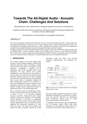
Towards The All-Digital Audio / AcousticChain: Challenges And SolutionsNicolas-Alexander Tatlas, Andreas Floros, Panagiotis Hatziantoniou and John N. MourjopoulosAudioGroup, Wire Communications Laboratory, Electrical and Computer Engineering DepartmentUniversity of Patras, 26500 GreeceCorrespondence: John Mourjopoulos (mourjop@wcl.ee.upatras.gr)ABSTRACTThe obvious advantages of digital audio technology have up to now being manifested mainly in media storage andprocessing sub-components, witch are parts of a more elaborate audio / acoustic analog reproduction chain. It isenvisaged that the remaining components such as cables, amplifiers and transducers will soon be also implementedin digital form, potentially leading to networked, integrated and highly optimized solutions.The paper examines theoretical and implementation aspects related to each of the modules that could constitute suchan all-digital audio / acoustic transducer, namely: (a) the digital wireless receiver, via the Bluetooth and IEEE802.11 protocols, (b) audio decoding and format adaptation (c) DSP for acoustic compensation, based on measuredresults for smoothed response equalization, (d) digital amplification, and, (e) all-digital transduction.subsystems within this chain, when possiblepresenting implementations and simulation testresults.1. INTRODUCTIONThe common element in all current digital audiosystems is a chain of largely analogue, inefficient andinflexible subsystems which are attached to digitalsources before sound reaches at the listener: (a) thecontroller / preamplifier / amplifier, (b) theloudspeakers and (c) the connecting cables. Thesesubsystems, for many decades have resistedstandardization and integration, but this problem isnow becoming even more pressing with the practicaldifficulties imposed on the user in order to combineand interconnect multichannel home and multimediaaudio set-ups. Hence, a significant challenge forfuture developments should be the evolution of auniversal and integrated solution to combine all thesesubsystems, allowing the wireless coupling of anynumber of digital acoustic transduction elements todigital audio sources, in networked applications.Fig 1: Overview of a possible form for the all-digitalaudio/acoustic chainHere, a potential scenario for integrating the abovemodules is discussed and analysed. According to this,as shown in Fig. 1, an integrated all-digitaltransducer should be allocated per audio channelallowing self-powered, adaptable and controllablewireless operation, so that stereo or multichannelsignals of any of the current or future digital formatscould be appropriately received, decoded, processed,amplified and acoustically reproduced. In moredetail, this paper will discuss the problems andexamine the merits of possible solutions for criticalThe paper initially considers the potential of currentBluetooth and IEEE802.11a/b protocols for wirelesslocal area networks (WLANs), for multichannelaudio transmission, largely based on resultspreviously presented by the authors [11].A subsequent section discusses general requirementsfor the decoding module which could allowcompressed or non-compressed format audio to beconverted to PCM stream in each channel receiver.1
It is also likely that the response of each receiver maybe sub-optimal due to physical restrictions in alldigital transduction, or even, its positioning inside thelistening environment. For this, a potentialequalization scheme is proposed, based on complexsmoothing and equalization of each channel’scombined audio/acoustic response [19]. Followingdecoding and processing, as shown in Fig. 1, eachchannel bitstream will have to be further adapted tothe format employed for subsequent digitalamplification and transduction. Given that PCM,Sigma-Delta modulation (SDM) and PWM appear tobe the most promising candidates, these potentialoptions are examined. With respect to these formats,issues related to the performance and complexity ofthe digital amplification module are examined(DAMP). The final section of the paper introducesnovel methodology and preliminary results related tothe potential implementation of Digital TransducerArrays (DTAs), fed by either multibit PCM or onebit signals (i.e. PWM or SDM). Hence, this sectionextends results presented previously [9], allowinguseful conclusions to be drawn on the respectivemerits and disadvantages of each signal format forsuch applications.Time-bounded applications, such as digital audiotransmission require a constant throughput. Sothey must be established through SynchronousConnection-Oriented (SCO) links. The effectivebandwidth in such a case is 64kbps for each link,with a maximum of 3 concurrent links. The establishment of SCO links creates abandwidth overhead, which dramaticallydecreases the transfer capabilities of any coexisting Asynchronous Connection-Less (ACL)link. The packet-switched nature of the ACL links,given the limited bitrate, is not suitable for realtime applications. Especially in noisyenvironments, packet retransmissions are appliedto ensure data integrity, which further reduce theeffective bandwidth.Given the above limitations of the Bluetoothstandard, the following considerations are necessaryfor realizing high-quality, real-time audioreproduction through Bluetooth: The original audio data must be compressedprior to the transmission.[11] Apart from the transmitted audio data, manyapplications may require the transmission ofcontrol information (e.g. volume control, timinginformation etc), which must be multiplexedwith the compressed audio data.Below, some results are discussed, based on aBluetooth audio implementation, reported in detail in[11]2.1.1. Bluetooth Mulitple LinksStereo and multichannel audio reproduction requiresthe concurrent transmission of discrete audiochannels to two or more playback devices. Fig. 2shows a typical example of a stereo application,where two audio channels ((L)eft and (R)ight)produced by an audio source (e.g. CD-Player, DVDVideo, etc) are compressed and individuallywirelessly transmitted to the corresponding Bluetoothenabled devices through two ACL links, able totransmit both audio and control information.2. WIRELESS NETWORKINGWired digital networking solutions are widelyaccepted for connecting digital sound sources tomultichannel decoders/amplifiers. The FireWireprotocol has been established as a good candidate forfuture audio networking technology. FireWire comesas enhancement to the SPDIF protocol, providingfaster bitrates, command and control, contentprotection and future flexibility. On the other hand,wireless protocols are widely employed for cablefree personal (WPANs) and local (WLANs)networking between workstations and otherelectronic devices. It is argued here that such wirelessoperation will greatly enhance the functionality andpotential for integration for future audio devices. Themost common digital networks employed, areBluetooth [12] (WPAN), and IEEE802.11b/a [13](WLAN).2.1. Bluetooth AudioLeft audio receiver (slave)audioAudioPlaybackControlBluetooth is an attractive wireless specification fordeveloping WPAN products, with a maximum rangeof 100m and a theoretical rate of 1Mbps. Theprotocol provides transmission of data and voice inpoint-to-point and point-to-multipoint setups.However, the bandwidth limitation together with thenature of the permitted wireless links between theconnected devices present some major drawbacks.More specifically:Link 1Audio source rce(R)BluetoothModuleAudioDecoderRight audio receiver (slave)Link ack2
allows the definition of the number ofretransmissions N, performed in broadcast mode(which is constant even if a packet is successfullytransmitted), the above losses are partially reducedwith increasing N with proportional reduction of theeffective bandwidth. Typical measurements of theeffective bitrate and the percentage of the lost audioinformation are presented in Table 1, as a function ofN.Fig. 2: Point-to-multipoint audio and user-controlledinformation transmission for stereo playbackThe maximum number of supported channels in thiscase is equal to: b -b N ch max i (1) b where bmax is the maximum available bitrate (equal to721kbps), b is the encoding bitrate (in kbps)employed for the compression of the audioinformation, bi (kbps) is the mean traffic of thecontrol data through all the established links and denotes floor integer truncation.Considering the case of concurrently transmittingaudio and control data through two ACL links forstereo reproduction, a mean effective bitrate valuewas measured at both playback devices equal to295kbps. However, the above application setupintroduces synchronization problems between thetwo playback devices, as different rates ofretransmissions are performed on the two ACL links.The above problem can be overcome by prebuffering an adequate portion of audio data, but thisdoes not affect a possible time-mismatch of thecontrol (user-defined) information, which is usuallyshort and practically not noticed.While the above application scheme is suitable asstereo reproduction scheme, the available bandwidthis inadequate for multichannel (e.g. 6-channel)reproduction.2.1.2. Bluetooth nsmission, is to employ the broadcast capability ofthe Bluetooth standard, which overcomes the abovementioned channel limitation. As it is illustrated inFig. 3, in such a case, the multichannel audio contentis compressed and broadcasted, with the channelseparation taking place on each of the playbackdevices. Hence, it is required that channelidentification information should be assigned to eachreceiver in order to reproduce the appropriate audiochannel.In broadcast mode, the maximum number ofallowable connections of a master device to slavedevices equals to seven, thus a maximum of sevenaudio channels can be transmitted. Hence, apart fromtypical stereo applications, all current multichannelplayback formats can be supported (e.g. AC-3coding, DTS, etc). During tests, data integrity wasnot found to be assured, as no dynamicretransmission mechanism is applied in such a case.Hence, the reproduction in this case was justacceptable, due to packet losses introduced in thewireless path. Since the Bluetooth specificationAudio receiver 1 (slave)AudioPlaybackControlLink dio.Audio source (master)(L)AudioBluetoothCoder (R) ModuleAudio receiver N (slave)Link kFig. 3: Wireless multichannel transmission usingpoint-to-multipoint connection setup in broadcastmodeNbe (kbps)01551325Audio datalosses7%-9%2%-3%Table 1: Measured effective bitrate and audio datalosses as a function of retransmissions performed inBluetooth broadcast mode (for 1m distance).Given that the packet losses are introduced tocompressed audio data, the final audio reproductionis highly distorted. Moreover, as the losses vary inlength and time occurrence between the two ACLlinks, they additionally introduce “phase” distortionbetween the two reproduced audio channels. Theabove observations seem to represent majorrestrictions for the development of multichannelaudio applications, which given the bandwidthlimitations of the Bluetooth protocol must be realizedin broadcast mode. In practice, the above problemscan be overcome by developing mechanisms in boththe Bluetooth lower layer stack and the applicationlayer, designed to perform packet loss signaling andretrieval procedures, as well as appropriate audiodata restoration routines.2.1.3. Bluetooth ConclusionsThe conclusions drawn from the study of theBluetooth protocol [11] can help in assessing theoptimal Bluetooth-based transmission parameters for3
communicate directly with each other in a peer-topeer manner.For audio device networking, an ad-hoc setup seemsto be the most appropriate solution, because of thereduced cost and the better performance provided.The latter is in general true for a limited number ofusers: given that the maximum number of wirelessaudio devices operating in such a network should notbe more than 7 (one audio transmitter and sixreceivers) the constraint is met.In order to transmit audio through a IEEE802.11 adhoc network for stereo or multichannel reproduction,the multicast/broadcast capability of the protocolmust be employed. Multicasting refers to sendingdata to a select group whereas broadcasting refers tosending a message to everyone connected. The IEEE802.11 multicast/broadcast protocol is based on theprocedure of Carrier Sense Multiple Access withCollision Avoidance. The protocol does not offer anyrecovery mechanisms for the above data frames. As aresult, the reliability of the multicast/broadcastservice is decreased because of the increasedprobability of lost or corrupted frames resulting frominterference or collisions.There are two alternatives in order to solve the abovementioned issue: the first is using one of the manyproposed reliable multicast protocols, wheremodifications are made to the MAC layer in order toadd data integrity mechanisms [15]. However, suchan addition could lead to synchronization problemsbecause of the recovery mechanisms employed, asdiscussed with the Bluetooth protocol. Sincethroughput is not an issue with 802.11b or 802.11afor audio purposes, a second potential approachwould be to transmit in a high definition coding thatis “resistant” to errors and additionally develop analgorithm that analyzes corrupt frames (identifiedthrough faulty CRC), using undamaged componentsand recreating the rest through interpolationtechniques. Reduction of audio quality in this caseshould be a matter of future investigation.3. DECODINGcompressed quality, real-time audio playback. Fig. 4maps the measured effective bit rate (for 1mdistance) with the audio data bitrate, indicating themaximum allowed compressed audio bitrate for alltest cases considered. Ideally, uncorrupted real-timeaudio reproduction requires an effective bandwidthvalue at least equal to the compressed data bitrate.This condition is graphically represented by the Realtime threshold line. For all transmission casesexamined, the maximum allowed compression bitrateis defined by the point of intersection of the meanmeasured effective bitrate value with the real-timethreshold line. For example, from this figure it can bededuced that stereo audio and control informationtransmission (2 discrete ACL connections) ispossible when each audio channel is encoded at amaximum of 256kbps (Stereo), while this rate isincreased to 320kbps or higher when a single ACLlink is considered (Mono).700DH5Mono - Lp 40k600DH3500Effective bitrate (b e - kbps)Broadcast (No retransmissions)400Broadcast (1 retransmission)DM5320DM3Stereo - Lp 40k256192128112Re96ial-tmre thoeshld lDH1i neDM1646496112128192256320 and higherTotal compressed audio bitrate (kbps)Fig 4: Mapping diagram of the audio data bitrate andthe maximum allowed compressed audio bitrate forall test cases examined, for 1m distance (from [11])2.2. IEEE802.11 Audio NetworkingIEEE 802.11b and 802.11a are WLAN standards,used over large distances (up to 500m for accesspoints) and theoretical data rates of 11Mbps for802.11b and 54Mbps for 802.11a. The IEEE 802.11specifications address both the Physical (PHY) andMedia Access Control (MAC) layers while the othersremain identical to the IEEE802.3 (Ethernet).Two different setups for WLAN networks exist,“infrastructure” and “ad hoc”. Infrastructure moderequires the use of at least one access point (AP),providing an interface to a distribution system. In thiscase, all network traffic goes through the AP. The“ad hoc” mode allows the network module to operatein an independent basic service set (IBSS) networkconfiguration. With an IBSS, the devicesOne of the goals of the system in Fig. 1 is toimplement decoders for low-latency streaming ofcompressed or non-compressed digital audio datadelivery data through wireless networks.Typically, the following digital audio formats mayhave to be incorporated on the decoder: Uncompressed two or multi-channel PCM audio(16 up to 24 bit resolution, 44,1 up to 192KHzsampling) Uncompressed DSD multichannel, at 6.2Mbit/s Stereo MPEG-1 Layer 3 (mp3) coding, based onthe ISO-MPEG Audio coder IEC11172-3. Bit4
rates supported will be in the range of 128kbit/sup to 320kbit/s as defined by the standard. Dolby Digital 5.1 multichannel coding based onthe ATSC A/52 Digital Audio CompressionStandard (AC-3). Typical rates of the AC-3bitstream are 384kbit/sec up to 640kbit/sec. Multichannel MPEG-2 coding, based on theISO/IEC 13818-3 standard. The typical bitratefor MPEG-2 bitstreams extend up to 684 kbit/sfor multichannel reproduction. low latency subband coding formats (SBCcodec), based on the specifications of themandatory codec for the Advanced AudioDistribution Profile of Bluetooth, which iscurrently [14] under a standardization (voting)procedure. The bitrates supported will be in therange of 200 to 600 kbits/s.The decoder module for the first four cases must bebased on the corresponding standards. However achallenge here is to incorporate reliable extraction ofhigh-priority data (e.g. header information) receivedthrough the wireless channel, which is essential forthe decoding process.The low-latency SBC codec has the aim to providereal-time encoding and decoding of a live audiostream, for example, the sound channel of a TVprogram.components. In the frequency domain, theequalization corrects gross spectral effects due toearly room reflections, without attempting tocompensate for many of the original narrowbandwidth spectral dips.Time Energy (dB)0-10-20-30OriginalEqualised-40141618202224Time (msec)(a)30Magnitude (dB)204. PROCESSING100-10-20OriginalEqualised-30The all-digital transducer should incorporatesufficient DSP power, not only to realize simplefunctions such as volume control, delay, shelvingfiltering, but also to implement transducer responsecorrection and adaptation to its local acousticenvironment via the use of equalization methods.These can incorporate FIR filtering on PCM data byusing room response inverse filters derived fromresponses individually measured for each of thechannel receivers.The acoustic response digital equalization methodproposed here, is based on an inverted complexsmoothed acoustic room response scheme thatovercomes many known problems [18-19]. Thefilters derived from the use of the above method canbe implemented on the processor/decoder DSPwithin the practical limits for the FIR filters’ length,taking into account possible requirements for thelow-latency operation.An example of a room response function before andafter the proposed complex smoothing equalization isshown in Fig. 5. As it can be observed, in the timedomain the equalised response has more powershaped in the direct and early reflection path and lesspower allocated in some of the reverberant-40101001k10klog Frequency (Hz)(b)Fig. 5: Room Response before and after the proposedequalization method: (a) Time domain (Energy) (b)Frequency domainThe implementation of the proposed equalizationscheme is shown in Fig. 6. The sound material mustbe pre-filtered in real-time by the equalization filter,derived from an appropriately smoothed responseversion, implemented within each channel receiver,and then it is reproduced via the audio chain into ssible on-line measurement5
Fig. 7: Results for of measured acoustic spaceresponses before and after equalization: (a) Clarity(C80) vs Volume (b) Spectral Deviation vs VolumeFig. 6: Implementation scheme for the proposedaudio/acoustic equalization method.As was reported in [19], all tested and wellestablished objective acoustic criteria, were found toimprove after the application of smoothed responseequalization, for a number of tested spaces, rangingfrom a small office to a 1000-seat auditorium.Furthermore, the majority of listeners preferred theequalized sound material, in a real-time test.Specifically, the Clarity (C80) criterion, known todescribe the perceived acoustic effects on musicpresentation, seemed to improve, irrespective of theroom’s volume, typically as is shown in Fig. 7. TheRoom Transfer Function amplitude SpectralDeviation was also found to be reduced afterequalization, for all spaces, by an amount generallyproportional to the degree of the room’s originalspectral irregularity, which was not always increasingwith its volume.Subjective tests, have also confirmed a preference forsuch room-corrected audio material, when waspresented in real-time in a listening environment [19].5. AMPLIFICATIONA complete digital-audio/acoustic chain requirespower amplification of the audio signal in its digitalform without prior analog conversion.The switching operation of the power transistorsemployed form amplification of digital audio pulsesyields very high power efficiency, which representsone of the major advantages of digital amplificationsystems. Theoretically, assuming ideal switchcomponents, the amplification performance is 100%,which means zero heat dissipation. In practice, theefficiency is limited to 80-90%, affected by the nonzero resistance of the switches [1]More specifically, if P0 (W) is the input power fed tothe amplifier, the real output power is given by:Pout P0- Plosswhere Ploss (W) is the total power losses due to thenon-ideal power switches (all the other possiblepower dissipation reasons are ignored for simplicityreasons). It is obvious that Ploss depends on thenumber of times that the power switches arechanging their state, which in general corresponds tothe Pulse Repetition Frequency (PRF) of the controlpulse stream [2]. Assuming that each state-changeresults to Pl0 power losses, eq. 2 becomes:2118C80 (dB)15OriginalEqualised129 PPout P0 1 2 l 0 PRF aP0P0 6301001kwhere α is the efficiency factor (α 1). The currentpower switching technology implies a maximum PRFof 300 up to 500kHz in order to achieve high powerefficiencies [3].(a)109Original8EqualisedUp to now, multibit Pulse Code Modulation (PCM)was considered as the de facto signal format for thecontrol of the power switches. Although PCM audiomeets the requirement of PRF 500kHz mentionedabove, the multibit nature of such data introduces apractical restriction towards PCM-based all-digitalamplifiers: assuming an N bit resolution (typicallyN 16 or more) and a sampling frequency equal to fs(Hz), the PCM signal values are represented by 2Ndiscrete levels and the direct digital amplification ofsuch a signal would require 2N power switchtopologies operating at a frequency fs. Nevertheless,as will be discussed in Section 6, lower resolution765432100(3)10k3log Volume (m )Spectral Deviation (dB)(2)1k10k3log Volume (m )(b)6
PCM maybe employed to drive a digital transducer,which may alleviate such problemsfp 2(2N-1)fs (Hz)(4)where N is the digital input signal bit resolution.Over the last decades, the use of 1-bit audio signalshas emerged as an attractive practical alternative tomultibit PCM audio. For digital amplificationpurposes, the 1-bit coding technology overcomes theabove practical restriction of the excessive powerswitch number, requiring only a set of four powerswitches connected together in an H-bridge topology(e.g. as in an analog class D amplifier) at the expenseof a much higher operating frequencies implied bythe 1-bit sampling rates (typically Rxfs, where R isthe factor of the oversampling employed prior to 1bit conversion). This introduces electromagneticinterference problems, increases the implementationcomplexity (mainly in terms of circuit design andcomponent requirements) and decreases theamplification efficiency, given that the average PRFis increased.Current efforts are considering two well-known 1-bitcoding formats for developing all-digital amplifiers:(a) 1-bit Sigma/Delta Modulation (SDM) asemployed in DSD, and (b) Pulse Width Modulation(PWM). Both approaches follow the same basicstructure, with the overall amplification performancestrongly depending on the modulation characteristics.Assuming a 44.1kHz initial PCM sampling rate andgiven that in the case of SDM, the bitrate of the 1bitoutput as well as the PRF is not constant, but isderived from and hence depending on the inputsample values, the SDM-based amplifiers shouldoperate at maximum clock frequencies of 3MHz.Hence, the measured power efficiency given by eq.(3) can vary with time, but in average, is lower thanfor the case of direct PCM amplification by a factorequal to the specific oversampling ratio employed.Moreover, SDM is known to suffer from slowlyrepeating bit-patterns (idle tones [2]), as well as highfrequency noise. A number of digital signalprocessing algorithms have been proposed in theliterature to solve these problems, such as thecontrolled SD bit-flipping [3] and high order noiseshaping techniques.On the other hand, PWM modulation was initiallyemployed in analog telecommunication systems.However, previous work [4] has shown that it can beanalytically described as a 1-bit digital codingtechnique by converting each quantised input valueto a fixed level pulse with proportional time width.The PRF in this case equals to the digital inputsampling frequency fs, achieving high amplificationefficiency according to eq. (3), while the final bit rateof the PWM bitstream is given by [4]:However, it is well known that PWM suffers fromharmonic and non-linear distortions, which decreasewith the switching frequency [5]. Hence, in order tokeep the overall distortion level low, increase of thePRF is required (typically by a factor of 64 [6]). Fortypical audio applications, this increases the final bitrate (fp) in the range of GHz, rendering itinconvenient for practical implementations. For thatreason, various PWM linearisation strategies havebeen developed [7], in the past, attempting tocompensate PWM-related distortions while keepingthe PRF as low as possible. Fig. 8 illustrates theeffects of applying the “Jithering” techniquedeveloped by the authors, which eliminates thePWM-induced distortions without increasing thePRF [8].20dB rel. Full Scale0-20-40-60-80-100-120-14005101520Frequency (kHz)Fig. 8. Distortion free PWM conversion using“Jithering” distortion elimination techniqueTable 2 summarizes the merits of all-digitalamplification technologies with respect to signalformats. Clearly, PWM 1-bit coding represents theoptimal choice for digital amplifiers, as it combineshigh power efficiency with low implementationcomplexity. High quality can be achieved using DSPpreprocessing algorithms. Moreover, as SDM-basedamplifiers offer lower efficiency, PWM can also beused in the case that the original audio content isSDM (e.g. as in DSD), by employing Pulse GroupModulation (PGM) [17]. As it is shown in Table 2,PGM was found to be an audibly transparent way forconverting a SDM pulse stream to PWM data, able tocombine the low switching frequencies of PWM andthe low final bitrates of SDM.7
6.1. Outline6.1.1. PCM Digital SpeakerPCMSwitching ratefsBitratefsxNEfficiencyDSP requiredPowerswitchesrequiredHighNo2N 1Table 2: fPWMPGMfsfs2(2N-1)fsRxfsHighYesHighYes44Fig. 9: PCM Digital Speaker b1,1 . . b1, m b 2,1 . . b2, m ,The input PCM signal S . . . bn,1 . . bn,m represented here as a N M matrix, where N is thenumber of bits per sample and M is the total numberof samples (in theory infinitely large). The signal isoriginally sampled at a frequency f s , can be oversampled R times, noise-shaped and re-quantized,thusprovidingthesignal b1,1 . . b1, m ' b 2,1 . . b2, m ' S ' Q[ S ] , resulting to a . . . bn ',1 . . bn ', m ' N ' M ' matrix, where M ' R M and N ' the newbit resolution per sample (generally N ' N ).N ' different bitstreams are then created, S '0 toS 'N ' 1 by extracting for each one a bit from aspecific position from every PCM sample. So,S '0 [1 0 . . 0] S ' , S '1 [ 0 1 . . 0] S 'all-digital amplifier6. TRANSDUCTIONA “digital loudspeaker” is a direct digital-signal toacoustic transducer, usually comprising of a digitalsignal processing module driving miniature elements,strategically positioned in order to reproduce theaudio digital data stream. The main advantage ofsuch loudspeaker is that the signal remains in thedigital domain and is converted to analog through theelement-air coupling. Other advantages of suchdigital arrays, relate to the flexible control of theirdirectivity [10], currently utilized for multichannelreproduction via a single array [22]. Such directivityfeatures are not addressed here, since the originalsystem is envisaged to comprise of discrete,networked receivers, each reproducing an individualaudio channel (Fig. 1).Current efforts for digital loudspeakers are focusingon multi-bit signals (PCM) [9] in two differentforms: Digital Transducer Arrays (DTA) andMultiple Voice Coil Digital Loudspeakers(MVCDL). Although the MVCDL appears to offeran attractive solution for many current-day practicalproblems, in this study the discussion will focus onDTA, as an alternative solution offering greaterpromise for a future integrated audio system design.Here a DTA scheme will be anaylsed, introducing anovel approach for examining its audio performance,for inputs covering all the prominent digital audioformats. Hence, the DTA will be driven by multibitPCM signal [9] and by one-bit signals such as PWMor DSD.Generally, a DTA consists of three stages (Figs9,10,11): digital signal processing (DSP) digital audio amplification (DAMP) (seeprevious section) digital acoustic emission (DAE)and S ' N ' 1 [ 0 0 . . 1] S ' .The bitstreams are then fed to groups of DAMPs,autonomously driving DAEs. In order to acousticallyreconstruct the original digital signal, the groups
an all-digital audio / acoustic transducer, namely: (a) the digital wireless receiver, via the Bluetooth and IEEE 802.11 protocols, (b) audio decoding and format adaptation (c) DSP for acoustic compensation, based on measured results for smoothed response equalization, (d) digital amplification, and, (e) all-digital transduction. 1. INTRODUCTION


