Transcription
responsible business solutionswww.metserve.com.auMETSERVEMining & Energy Technical Services Pty LtdTailings Storage Facility Management PlanMcARTHUR RIVER MINE PHASE 3DEVELOPMENT PROJECTJanuary 2012
Tailings Storage Facility Management PlanMcArthur River Mine Phase 3 Development ProjectThis report has been prepared solely for the benefit of Xstrata Zinc and McArthur River Mining PtyLtd. MET Serve accepts no liability for the use or interpretation of any information contained in thisreport for any other purpose other than the intended, or for its use by any party other than the abovenamed client.Mine Closure PlanMcArthur River Mine Phase 3 Development ProjectPO Box 306Fortitude Valley Post OfficeFortitude ValleyQLD 4006(ABN 94 143 463 316)
Appendix E1 – TSF Management PlanMcArthur River Mine Phase 3 Development ProjectTailings Storage Facility Management PlanJanuary 2012McArthur River Mine Phase 3 Development ProjectDraft Environmental Impact StatementE1-1
Appendix E1 – TSF Management PlanContents12Scope and Purpose . 51.1Overview. 51.2Existing TSF . 51.3Phase 3 Development Project – TSF Design Parameters . 5Potential Environmental Risks – TSF . 92.1TSF Risk Assessment . 92.2Environmental Protection Measures . 112.2.1 Tailings Deposition Method. 112.2.2 Embankment Construction . 112.2.3 Continued use of geopolymer barriers . 112.2.4 Recovery bore system around the TSF perimeter . 112.2.5 Flood protection for a 1-in-500 year event . 112.2.6 Thorough monthly monitoring program . 113Existing TSF Design, Construction and Performance . 123.1Overview. 123.1.1 Cell 1 . 123.1.2 Cell 2 . 123.1.3 Water Management Dam (Cell 3). 133.2Tailings Delivery and Deposition Method . 143.3Tailings Characterisation . 163.3.1 Tailings Properties . 163.3.2 Tailings Geochemistry . 163.3.3 Geotechnical Properties . 173.4Water Management . 173.4.1 TSF Water Management Schematic . 173.4.2 Tailings Water Management . 173.4.3 Existing Stormwater Management . 183.4.4 Cell 2 Spillway Design Upgrade . 193.4.5 Emergency Procedures – Extreme Rainfall Events . 213.5TSF Stability. 213.5.1 Long-Term Stability . 21McArthur River Mine Phase 3 Development ProjectDraft Environmental Impact StatementE1-2
Appendix E1 – TSF Management Plan3.5.2 Water Balance Modelling . 213.5.3 Erosion Modelling . 223.5.4 Erosion Protection . 223.6TSF Cover. 233.6.1 Proposed TSF Cover Design . 233.6.2 Previous TSF Cover Design Modelling . 243.7TSF Seepage Mitigation . 253.7.1 Background . 253.7.2 Existing Seepage . 263.7.3 Previous Seepage Modelling. 273.7.4 Previous Seepage Control Measures . 283.84Previous MRM TSF Investments and Upgrades . 30Proposed TSF Expansion – Cell 4 . 314.1Location . 314.2Hydrogeology . 314.3TSF Cell 4 Embankment Design . 314.4Inferred Tailings Behaviour . 324.4.1 Tailings Dam Densities . 334.4.2 Tailings Water Recoveries . 334.4.3 Tailings Permeabilities . 33564.5Geotechnical Review and Implications . 334.6Project Seepage Modelling . 344.7Future Seepage Quality and Control Measures . 35TSF Monitoring and Inspection . 375.1Monitoring Objectives . 375.2TSF Inspection and Reporting Schedule . 375.3TSF Structural Monitoring . 375.4Geochemical Monitoring . 375.5Future Environmental Monitoring. 385.6Extreme Weather Events Monitoring . 385.7TSF Reporting Schedule . 39Rehabilitation and Decommissioning . 40McArthur River Mine Phase 3 Development ProjectDraft Environmental Impact StatementE1-3
Appendix E1 – TSF Management Plan76.1TSF Decommissioning Objectives . 406.2TSF Rehabilitation Strategy . 406.3Final TSF Land Use . 426.4TSF Rehabilitation Monitoring . 426.5TSF Closure Monitoring . 436.6TSF Rehabilitation Reporting . 436.7Closure Personnel . 44Previous TSF Commitments . 457.1Draft EIS Commitments (August 2005) for Major Open Cut 25 Year Mine Life . 457.2Supplement to Draft EIS December 2005 . 467.3Public Environmental Report July 2006 . 467.3.1 Section 7.0 Tailings Storage Facility . 467.48MRM Mine Management Plans . 47References . 48McArthur River Mine Phase 3 Development ProjectDraft Environmental Impact StatementE1-4
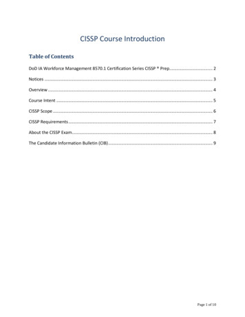
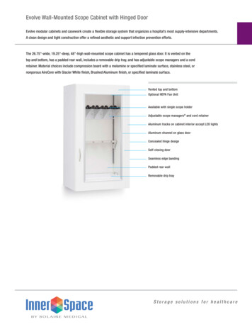
Appendix E1 – TSF Management Plan1Scope and Purpose1.1OverviewThis document provides a summary of the Tailings Storage Facility (TSF) design and current and futuremanagement practices at the McArthur River Mine (MRM). It has been prepared for submission with theDraft Environmental Impact Statement (EIS) for the McArthur River Mine Phase 3 Development Project (theProject) as supporting information for the proposed TSF expansion.Tailings are water-based fine waste products generated through MRM’s ore processing operations that arecurrently taken by pipeline to the TSF. Tailings are essentially the slurried waste products left over from theproduction of MRM zinc product (bulk concentrate). Tailings have been produced and sent to the existing TSFsince the commencement of operations in 1995.1.2Existing TSFThe TSF is located within the Project area on the western side of the Carpentaria Highway, south of SurpriseCreek. The maximum disturbed area at the TSF to complete the current approved operations would beapproximately 380 ha. The TSF enclosure is bounded by a 6,670 m engineered clay perimeter wall.Cell 1 of the TSF, which is closest to Surprise Creek, has been decommissioned and is now undergoingrehabilitation. The successful rehabilitation of Cell 1 will serve to inform MRM’s future seepage managementand development plans.Cell 2 is now used for tailings deposition, with water re-drawn to the processing plant and recycled. In 2010,MRM increased its recycled water usage by 17% on the previous year to more than 95% of all water usedonsite.Cell 3 is not currently in use for tailings deposition. It is used as a water management dam for fresh waterevaporation purposes and as an overflow depository for Cell 2 decant water. Cell 3 will be used for tailingsdeposition in future years of the operation.The existing TSF is shown in Figure 1. The existing TSF is an already approved structure at McArthur RiverMine and is not subject to the Project’s EIS process.1.3Phase 3 Development Project – TSF Design ParametersThe existing and approved TSF footprint will be utilised for the Project’s operations, but additional landdisturbance will be necessary to accommodate all of the tailings that will be produced by the Project. TheProject includes the utilisation of a fourth TSF cell that is planned to adjoin Cells 2 and 3 on the northwestside of the current TSF (Figure 2).To construct Cell 4, an additional 2,350 m of embankment wall will be required. The internal wall betweenCell 4 and the existing TSF will be 1,460 m. The initial construction to RL 55 m will have a surface area of 65ha and have a capacity of 4,300 ML.At its final height of RL 61 m, the surface area of Cell 4 will be 68 ha and the capacity will be 8,400 ML. Cell4 will initially be used for water storage until approximately 2032 when tailings deposition will commenceafter Cell 3 is full. The maximum disturbance at the TSF for the Project will be 460 ha.The Project will extend the life of the mine to 2036. Life of Mine (LOM) characteristics and key designparameters of the TSF are detailed in Table 1:McArthur River Mine Phase 3 Development ProjectDraft Environmental Impact StatementE1-5
Appendix E1 – TSF Management PlanTable 1MRM TSF CharacteristicsParameterExisting TSFProposed TSFTotal surface area380 ha460 haUltimate landform surfaceRL 68 mRL 68 m (RL 61 m for Cell 4)Maximum height of landform35 m (northern corner)35 m (northern corner)Total tailings storage capacity47,600 ML56,000 ML34Total TSF cellsCell 4 is required at the site initially for water management purposes, and will be subject to approval underthe Northern Territory Mining Management Plan process.McArthur River Mine Phase 3 Development ProjectDraft Environmental Impact StatementE1-6
S:\Projects\XZ003 MRM Extension EIS\ MapInfo\Workspaces\XZ003 M100A.cdrMcArthur River MinePhase 3 Development Project0200400Existing TSFMetresScale: 1:11,000 (A3)Data Source: Allan Watson Associates21/12/2011Datum/Projection:Mine Grid SystemFIGURE 1
S:\Projects\XZ003 MRM Extension EIS\ MapInfo\Workspaces\XZ003 M101B.cdrMcArthur River MinePhase 3 Development Project0200400Proposed TSF with Cell 4MetresScale: 1:11,000 (A3)Data Source: Allan Watson Associates21/12/2011Datum/Projection:Mine Grid SystemFIGURE 2
Appendix E1 – TSF Management Plan2Potential Environmental Risks – TSF2.1TSF Risk AssessmentA risk identification and mitigation approach has been adopted to ensure that the design, operational andclosure criteria for the TSF will have minimal risk of impacts to the receiving environment.A low risk rating will be achieved because of the ‘multiple lines of defence’ approach that has been taken toTSF management. Risk minimisation aspects include: the predicted long-term seepage volumes are generally low and are of the order of 30 to 40 L/day/mwidth of the TSF wall because of the relatively low permeability of the embankment core, the tailingsand the underlying dolomitic siltstone material decant water will be stored at the centre of the TSF, rather than on the periphery thereby reducingthe potential for seepage under the embankment the tailings will be deposited sub-aerially in thin layers, maximising the density of the tailings beachagainst the embankment, thus providing a low permeability layer between the decant water pondand the perimeter embankment the perimeter spigot discharge system maintains an appropriate level of saturation/moisture withinthe tailings beach during the cycling between the spigots, limiting the potential for oxidation oftailings that could generate sulphates/acidic water geochemical testing indicates that the tailings have an inherent Acid Neutralising Capacity (ANC),reducing the risk of the tailings oxidising and generating acidic conditions the underlying basement sequence has significant buffering capacity, should acidic seepage begenerated any seepage that does occur will be contained by a combination of measures including the lowpermeability clay core and cut-off key in the TSF embankment, the geopolymer cut-off barrier, thenetwork of recovery bores and surface perimeter drains, and underliner drainage to designedcollection zones water balance modelling indicates that the TSF water management dam will comply with its targetoverflow probability of a 1-in-500 year annual exceedance. Should such an unlikely large rainfallevent occur, any discharge from the TSF would be into a significant flood flow with dilutionsestimated to be greater than 1,000 times capping and revegetating the TSF progressively and after mine closure will limit the potential forfuture oxidation of the stored tailings, and enable clean runoff to be discharged to the surroundingenvironment operation of the seepage recovery bores after mine closure (if required, based on monitoringperformance) will reduce the groundwater head within the TSF, so that expression of ongoingseepage will not occur on the surface a comprehensive monitoring program will be maintained over the life of the TSF and will include thefollowing components: piezometric levels within the embankment surface water monitoring groundwater monitoring water quality decant pond water levelsMcArthur River Mine Phase 3 Development ProjectDraft Environmental Impact StatementE1-9
Appendix E1 – TSF Management Plan decant pond water quality embankment condition. MRM will continue to be responsible for post mine closure monitoring, and maintenance of therecovery system (if required), until closure criteria have been met and it is demonstrated that recoverywells are no longer required.MRM has invested more than 10 million since 2006 to continuously improve the performance andmanagement of the TSF.MRM is committed to reducing the off-site environmental risks of the TSF, as shown by the TSF commitmentsoutlined in Section 7.A summary of the TSF risks and contingency plans are shown in Table 2.Table 2TSF Risk Assessment, Mitigation Measures, and Contingency PlansRiskMitigationMonitoringContingencySurface wateroverflowRunoff and decant water to flow toWater Management Dam.Water Management Dam designedto be above the 1 in 500-year floodlevelMaintain a suitable freeboard beforeeach wet season.All runoff and decant water in theWater Management Dam to bereused in the processing plant,evaporated or discharged as per thedischarge license.Regular updating of the waterbalance modelling of the site watermanagement system, to minimiseoverflow risk.Regular inspection of the decantsystem, to ensure efficientoperation.Pump water from WaterManagement Dam toother storages.Increase the capacity ofthe Water ManagementDam.Discharge as perapproved dischargelicenses.Failure of TSFembankmentDesign in accordance with ANCOLDguidelines for high hazard dams.Engineering analysis of embankmentstability has confirmed a factor ofsafety well in excess of minimumrequirements.Regular inspection of embankmentintegrity to be undertaken.Monthly piezometric monitoring ofphreatic surface levels withinembankment.Independent annual inspections.Engineered remediationmeasures in accordancewith ANCOLDguidelines.Erosion ofouter face ofTSFembankmentOnly hard durable NAF rock that isresistant to erosion is to be used onouter face.Regular inspection of rock faceintegrity to be undertaken.Replace any rocksshowing signs of erosionwith more competentmaterial.Seepage fromTSFEmbankment has clay core with cutoff key.Ponded water in TSF kept away fromperimeter embankment.Geopolymer barrier installed aroundeastern embankment.Network of recovery bores installedin identified seepage areas.TSF to be capped with lowpermeability layer, to preventongoing entry of water at closure.Maintain recovery bores post closure(if required), until seepage head inTSF reaches design level.Ongoing monitoring of seepagerates through recovery bores andobservation bores.Monthly inspection ofembankment for evidence ofseepage.Increase the number orpumping rate ofrecovery bores.Install seepage collectiontrenches.McArthur River Mine Phase 3 Development ProjectDraft Environmental Impact StatementE1-10
Appendix E1 – TSF Management Plan2.2Environmental Protection MeasuresMRM considered a number of options for the TSF design but found the best is one which combines six ‘linesof defence’ or strategies to guard against seepage and to protect the environment. This strategy will be usedfor the design, operation, and ultimate closure and rehabilitation of the TSF and will be reviewed andupdated regularly. These six strategies for environmental protection are detailed below.2.2.1Tailings Deposition MethodSpreading the tailings in thin layers against the cell wall provides a ‘beach’ of tailings between the water andthe wall which will prevent water from seeping. This also offers a number of benefits in the management oftailings as it: supports the system of raising the embankments to increase the tailings capacity limits the potential for oxidising tailings thus generating sulphates (salt deposits).2.2.2Embankment ConstructionThe high embankment around the outside of the TSF is made of compacted clay covered with rocks with alow permeability. This two metre thick, four-layered embankment cap is designed to be safe and stable inboth wet and dry seasons. Only Non-Acid Forming (NAF) material is used for this outer surface to ensurethere are no contaminants in the water runoff.Proper design and construction will occur for the TSF until the end of mine life.2.2.3Continued use of geopolymer barriersIn the past two years, MRM has successfully trialled a geopolymer barrier on 2.25 km of the existing TSF wall.Under this system, a glue-like polymer is injected every two metres around the base of the TSF wall. Thisforms a hard barrier that minimises seepage outside the wall. The barrier will be applied to other areas ifrequired.2.2.4Recovery bore system around the TSF perimeterA recovery bore system around selected areas of the TSF perimeter wall will cut any seepage from the TSF offbefore it reaches freshwater systems. Seepage will be collected and pumped for recycling in the processingplant. These bores are between 10 m and 30 m deep. Monitoring data provides feedback on theperformance of the recovery bore system which feeds into design reviews.Plans show that these bores will be successful in trapping seepage within the footprint of the TSF and beforeit reaches the natural groundwater system. There are numerous mines in Queensland which use a similar TSFdesign strategy to MRM and these have been successful in protecting against environmental impact.2.2.5Flood protection for a 1-in-500 year eventThe height of the TSF embankment is greater than the 1-in-500 year flood levels. But an emergency spillwaywill be located in the north-west corner of the TSF to allow for overflows in extreme weather conditionsabove the 1-in-500 year levels. This is also based on the ANCOLD guidelines for the worst possible flood orrainfall experience.2.2.6Thorough monthly monitoring programWater levels within each TSF cell are checked daily. Groundwater and surface water quality are checkedthrough monitoring bores and water samples taken from the sediment ponds as well as Surprise and BarneyCreeks every month. TSF decant water is also monitored for levels and quality. The condition of theembankment is also inspected regularly.McArthur River Mine Phase 3 Development ProjectDraft Environmental Impact StatementE1-11
Appendix E1 – TSF Management Plan3Existing TSF Design, Construction and Performance3.1OverviewThis design for the MRM TSF is in accordance with the standards set by the Australian National Committeeon Large Dams (ANCOLD) Guidelines on Tailings Dam Design, Construction and Operation. Hence, the TSF isbuilt to the same safety standard as all major water storage dams. ANCOLD has specific guidelines forTailings Dam Design, Construction and Operation. These are regarded as the best practice standards underAustralian conditions and are recognised as the industry standard by State and Territory Governments.The existing TSF has been approved by previous environmental impact assessments and the informationpresented in this section is for supporting information in regards to the TSF expansion – Cell 4, which isdiscussed in Section 4.Descriptions of the existing TSF cells are shown below.3.1.1Cell 1The initial tailings impoundment area (containing the TSF and water storage), developed as part of the MRMunderground operation with the initial operational concept being for discharge of thickened tailings from anelevated, central location to form a conical shaped stack.The embankment configuration for Cell 1 construction as part of the initial development, is as follows: Embankment Crest Level External RL 49 m to RL 53.5 m Internal (Cell1/2) RL 48 m to RL 54.5 m Embankment Length External 2,000 m Internal 1,700 m Spillway/overflow level Western overflow RL 48.5 m Eastern overflow RL 48 m 3.1.2Total Cell 1 surface area: 78 ha.Cell 2The perimeter embankments of TSF Cell 2 were designed in accordance with the ANCOLD Guidelines (1999).Studies undertaken as part of the design include: characterisation of the physical properties of the tailings, foundation materials and potentialconstruction materials development of design criteria for a range of embankment loading conditions analysis of long-term embankment stability for a range of loading conditions.Based on the historic performance of TSF Cell 1, a revised TSF design concept was developed as part of theenvironmental impact assessment process for the conversion of MRM from an underground to an open-cutpit mine (Phase 2 Project) to improve the overall performance of the TSF, particularly with respect to seepage.McArthur River Mine Phase 3 Development ProjectDraft Environmental Impact StatementE1-12
Appendix E1 – TSF Management PlanThe location and design objectives of future TSF cells were developed with the following objectives: improved tailings placement techniques – the previous TSF cell (Cell 1) deposited tailings using acentral thickened discharge with water collected adjacent to the perimeter embankments anddiverted to water storage dams within the non-active deposition area of the TSF. Given the historicseepage from Cell 1, the tailings placement strategy has been changed to a perimeter spigoteddischarge with a central decant pond to keep water away from the perimeter embankments andhence reduce the potential for seepage provide stable landform – the Cell 2 perimeter embankments were designed in accordance with therequirements of the Australian National Committee of Large Dam Guidelines to ensure thatadequate factors of safety were provided across the landform both during the various stages of TSFdevelopment during mine operations and post mining after closure of the TSF. The designconsidered the geotechnical and seismic stability of the embankment materials as well as the surfacestability and erosion resistance of the outer slopes to both rainfall and potential flood events no excessive or uncontrolled emissions to the environment – based on the observed performance ofCell 1, additional design measures were developed for the future TSF cells to ensure that noexcessive or uncontrolled emissions to the environment arise from the TSF. The emissions ofparticular concern relate to dust, erosion of embankment slopes, surface runoff, and seepage minimise the area of the disturbance footprint – preliminary site layout studies considered thepotential to relocate the TSF. The footprint of the existing TSF was already approved by the NorthernTerritory Government for tailings disposal and had sufficient capacity to accommodate the expansionrequired for the Phase 2 Project. Furthermore, given the consistent subsurface conditions across thesite, there was no significant benefit in disturbing additional areas at the site as no sign
Appendix E1 - TSF Management Plan McArthur River Mine Phase 3 Development Project Draft Environmental Impact Statement E1-5 1 Scope and Purpose 1.1 Overview This document provides a summary of the Tailings Storage Facility (TSF) current and future design and management practices at the McArthur River Mine (MRM).