Transcription
OPERATOR’S MANUALThis manual provides information oninstallation, operating, maintenance,trouble shooting & replacement parts forCHICK-FIL-AREFRIGERATEDBREADING TABLE52365WPRM-CFANOTIFY CARIER OF DAMAGE AT ONCE.It is the responsibility of the consignee to inspect thecontainer upon receipt of same and to determine thepossibility of any damage, including concealeddamage. Randell suggests that if you are suspiciousof damage to make a notation on the delivery receipt.It will be the responsibility of the consignee to file aclaim with the carrier. We recommend that you do soat once.525 South Coldwater Road Weidman, MI 48893888-994-7636 Fax 888-864-7636 unifiedbrands.net7/24/2009PP MNL0502 rev C
Table of Contentspage 2 . Congratulationspage 3 Parts & Service Hotlinepage 3 . Serial Number Locationpage 4-7 .Randell Limited Warrantypage 8 Unit Specificationspage 9 .Unit Installationpage 10-12. .Unit Operationpage 13-15 .Preventive Maintenancepage 16 .Electrical Diagrampage 17 . Troubleshootingpage 18-20 . .Replacement PartsCongratulations on your recent purchase of Randell food service equipment,and welcome to the growing family of satisfied Randell customers.Our reputation for superior products is the result of consistent qualitycraftsmanship. From the earliest stages of product design to successive stepsin fabrication and assembly, rigid standards of excellence are maintained byout staff of designers, engineers, and skilled employees.Only the finest heavy-duty materials and parts are used in the production ofRandell brand equipment.This means that each unit, given propermaintenance will provide years of trouble free service to its owner.2800-621-8560
In addition, all Randell food service equipment is backed bysome of the best warranties in the food service industry and byour professional staff of service technicians.Retain this manual for future reference.NOTICE: Due to a continuous program of product improvement, Randellreserves the right to make changes in design and specifications without priornotice.NOTICE: Please read the entire manual carefully before installation. If certainrecommended procedures are not followed, warranty claims will be denied.MODEL NUMBERSERIAL NUMBERINSTALLATION DATEThe serial number is located inside the right door on the interior rearwall of the refrigerated base compartment.800-621-8560Randell Service and PartsHotlineunifiedbrands.net3
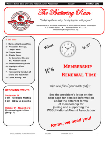
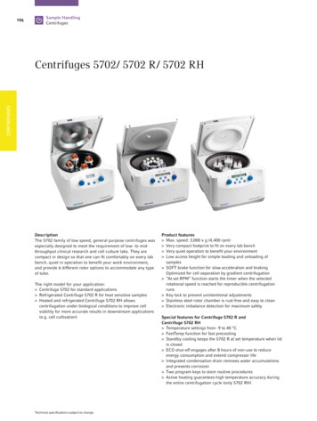
Unit 33"41.25"38.5"31/2115105-15P52.135492800-621-8560
Unit InstallationSELECTING A LOCATION FOR YOUR NEW UNITThe following conditions should be considered when selecting a location for yourunit:1. Floor Load: The area on which the unit will rest must be level, free ofvibration, and suitably strong enough to support the combined weightsof the unit plus the maximum product load weight. All casters must bein contact with the floor to support the weight. Casters may requireshims in order for the caster to be in contact with the floor.NOTE: If there is a question pertaining to weight load limits, consult thefactory at 1-800-621-8560.2. Ventilation: The air cooled self contained unit requires a sufficientamount of cool clean air. Also, avoid locating in an unheated room orwhere the room temperature may drop below 55 F (13 C) or about86 F (32 C).INSTALLATION CHECKLISTAfter the final location has been determined, refer to the following checklist prior tostart-up:1. Check all visible components for any potential damage2. Check that the condenser and evaporator fans rotate freely withoutstriking any stationary members.3. Power up unit once plugged in.4. Allow unit time to cool down to holding temperature.5. Refer to the front of this manual for serial number location. Pleaserecord this information in your manual on page 3 now. It will benecessary when ordering replacement parts or requesting warrantyservice.6. Confirm that the unit is holding temperature.7. Allow your unit to operate for approximately 45 minutes before puttingin food to allow interior of unit to cool down to storage temperature.NOTE: All motors are oiled and sealed.NOTE:FAILURE TO FOLLOW INSTALLATION GUIDELINES ANDRECOMMENDATIONS MAY VOID THE WARRANTY ON YOUR UNIT.ELECTRICAL SUPPLY: The wiring should be done by a qualified electrician inaccordance with local electrical codes. A properly wired and grounded outlet willassure proper operation. Please consult the data tag attached to the compressorto ascertain the correct electrical requirements. Supply voltage and amperagerequirements are located on the serial number tag located on the rear interior wall. .NOTE: It is important that a voltage reading be made at the compressormotor electrical connections, while the unit is in operation to verify thecorrect voltage required by the compressor is being supplied. Low or highvoltage can detrimentally affect operation and thereby void its warranty.unifiedbrands.net9
Unit OperationUNIT INFORMATIONMechanical Compartment1. The breading station is supplied with a main power switch.The switch is located on the rear of electrical box behindthe upper hinged vented door. The main power switch willcompletely shut down the upper rail as well as the lowerrefrigerated base.2. The rail power switch is located on the front of the electricalbox. The rail power switch will shut down the rail for nightlyshut down and cleaning. The lower refrigerated base willcontinue to cool when the rail power switch is off.3. Two digital temperature controls are located on the front ofthe electrical box. The upper control regulates temperaturefor the rail and the lower control regulates temperature forthe refrigerated base. (See Unit Operation page 11).4. The condenser filter indicator light is located on the front ofthe electrical box. If illuminated the condenser filter must becleaned or replaced. (See Preventative Maintenance page12).5. The condenser filter is located behind the lower hingedvented door. (See Preventative Maintenance page 12).6. The drain valve for the upper rail is found behind the upperhinged vented door. The rail may be drained by placing apan under the drain valve and opening the valve. (SeeEvening Shut Down of Prep Rail).Upper Rail Lid and Lift Mechanism1. The lid can be positioned three ways Fully closed Opened Fully openedNote: All cleaning of rail lift mechanism must be done while lid is in closed position. The tension of thelift mechanism has been pre-set at the factory.10800-621-8560
Unit Operation - cont.MORNING STARTUP OF PREP RAIL1. Unit cleaning may be performed at this time.2. Turn on unit. Power switch for rail is found behind upper hinged venteddoor.3. Allow a minimum 45 minutes for your unit to cool down before loadingproduct.4. Load the product and proceed with food preparation.Note: Product entering unit must be at 41 F or less.EVENING SHUT DOWN OF PREP RAIL1. Remove product from unit at the end of the day’s preparation.2. Turn off unit3. Unit cleaning may be performed at this time if the frost has melted offthe surface.4. Once defrosted, the rail drain may be opened to remove any water thathas resulted from the defrosting procedure.TEMPERATURE CONTROLSYour refrigerated breading table is equipped with a temperature adjustment controlfor the refrigerated rail as well as a temperature adjustment control for therefrigerated base which are located inside the mechanical housing behind theupper hinged vented door.Figure 1 illustrates the outer panel of the mechanical housing. The upper temperature control is forthe refrigerated rail and the lower temperature control is for the refrigerated base.unifiedbrands.net11
Unit Operation - cont.To raise temperature in the refrigerated rail:A. Push and hold the “set” button until 34 appears then release the “set”button. 34 is the current set point temperature.B. Push and release the up arrow 2 times until 36 is displayed. Push andrelease the “set” button one time. The new set point, 36, will flash 3times and then will be locked in.To lower temperature in the refrigerated rail:A. Push and hold the “set” button until 34 appears and then release the“set” button. 34 is the current set point temperature.B. Push and release the up arrow 2 times until 32 is displayed. Push andrelease the “set” button one time. The new set point, 32, will flash 3times and then will be locked in.NOTE: It is recommended to only make changes of 2 degree incrementsat a time. Allow for the unit to operate 24 hours between adjustments. Ifthe 2 degree adjustment is not enough another adjustment can be made.The maximum highest setting is 38 degrees and the minimum lowestsetting is 28 degrees. If the settings need to go above or below this pointthere may be other contributing factors as to the cause of thetemperature variances, please contact the factory at 1-800-621-8560.To raise the temperature in the refrigerated base:A. Push and hold the “set” button until 34 appears then release the “set”button. 34 is the current set point temperature.B. Push and release the up arrow 2 times until 36 is displayed. Push andrelease the “set” button one time. The new set point, 36, will flash 3times and then will be locked in.To lower temperature in the refrigerated base:A. Push and hold the “set” button until 34 appears and then release the“set” button. 34 is the current set point temperature.B. Push and release the up arrow 2 times until 32 is displayed. Push andrelease the “set” button one time. The new set point, 32, will flash 3times and then will be locked in.NOTE: It is recommended to only make changes of 2 degree increments at atime. Allow for the unit to operate 24 hours between adjustments. If the 2degree adjustment is not enough another adjustment can be made. Themaximum highest setting is 38 degrees and the minimum lowest setting is28 degrees. If the settings need to go above or below this point there may beother contributing factors as to the cause of the temperature variances,please contact the factory at 1-800-621-8560.12800-621-8560
Preventive MaintenanceRandell strongly suggests a preventive maintenance program which would includethe following monthly, weekly, and daily procedures:If a failure of the equipment is a direct result of any of the PreventativeMaintenance guidelines being neglected, the repairs and parts replacements willnot be covered under warranty.It is recommended that the customer contact the local Authorized Service Agent toprovide a quote to perform periodic Preventative Maintenance.Cleaning of all condenser coils on a monthly basis. Condenser coils are a criticalcomponent in the life of the compressor and must remain clean to assure properair flow and heat transfer. Failure to maintain this heat transfer will affect unitperformance and eventually destroy the compressor. Clean the condenser coilswith coil cleaner and/or a vacuum, cleaner and brush. Proper care of the filter willreduce the need for this task. See item #6.1A. Open lower louver ventilation door for the compressor compartmentand remove mesh filter to view the condenser coil. Use brush attachmentfor vacuum in this area to vacuum all particles out of this area.NOTE: Brush coil in direction of fins, normally vertically as to not damage orrestrict air from passing through condenser.1B. Remove 4 phillips screws on right exterior side of compressorcompartment to gain access to condensing unit. Vacuum all loose particlesthat can be seen being careful not to damage any wires or copper lines.1C. Blow out condenser coil from rear to front of unit with compressed air(30 PSI maximum). Forcing air in this direction allows the particles to exitthe same direction in which they had entered.Accessing the Mechanical HousingStep 1: Remove 4 screws.Step 2: Pull off side panel.Step 3: Access components.2. Clean and disinfect drains with a solution of warm water and mild detergent ona monthly basis.unifiedbrands.net13
3. Clean and disinfect drain lines and evaporator pan with a solution of warm waterand mild detergent on a monthly basis.4. Clean all gaskets on a weekly if not daily basis with a solution of warm waterand a mild detergent to extend gasket life.5. Clean the grease filter on a weekly if not daily basis with either hot water, milddetergent, or by cycling through a dishwasher.6. Clean upper lid hinge mechanism on a daily basis with a damp cloth containinga solution of warm water and mild detergent to remove any debris that mayinterfere with the hinge function.Note: The upper lift mechanism must be cleaned while the lid is in the downposition. Do not lift the lid while cleaning.Wipe along roller guide as well as the surface the roller rolls alongNOTE: DO NOT USE SHARP UTENSILS FOR ANY OF THE ABOVEPROCEDURES.JOBCLEANING AGENTCOMMENTSRoutine cleaningSoap, ammonia, detergent MedallionApply with a sponge or clothFingerprints and smearsArcal 20, Lac-O-Nu, EcoshineProvides a barrier filmStubborn stains anddiscolorationCameo, Talc, Zud, First ImpressionRub in the direction of thepolish linesGreasy and fatty acids,blood, burnt-on foodsEasy-Off, Degrease It, Oven AidExcellent removal on allfinishesGrease and OilAny good commercial detergentApply with a sponge or clothRestoration/PreservationBenefit, Super SheenGood idea monthlyReference: Nickel Development Institute, Diversey Lever, Savin, Ecolab, NAFEM.NOTE: Do not use steel pads, wire brushes, scrapers, or chloride cleanersto clean your stainless steel.CAUTION: DO NOT USE ABRASIVE CLEANING SOLVENTS, AND NEVERUSE HYDROCHLORIC ACID (MURIATIC ACID) ON STAINLESS STEEL.14800-621-8560
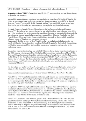
STEPS FOR REMOVING THE GREASE FILTER FOR CLEANINGStep 1: Locate grease filteron the front of the condenserair in duct. Behind lower hingedvented door.Step 2: Locate finger holeopening to remove filter withoutthe use of tools.Step 3: Insert finger and forcefilter upwards.Step 4: Filter should fallout in your hands.Step 5: Pull downwards torelease the filter at the top.Step 6: Filter should fallout of the top holding bracket.Step 7: Removing the filter alsoalso allows access to thecondenser for cleaning.Proper maintenance of equipment is the ultimate necessity in preventing costlyrepairs. By evaluating each unit on a regular schedule, you can often catch andrepair minor problems before they completely disable the unit and becomeburdensome on your entire operation.For more information on preventive maintenance, consult the local ASA orCFESA member. Most repair companies offer this service at very reasonablerates to allow you the time you need to run your business along with the peace ofmind that all your equipment will last throughout its expected life. These servicesoften offer guarantees as well as the flexibility in scheduling or maintenance foryour convenience.Randell believes strongly in the products it manufactures and backs those productswith one of the best warranties in the industry. We believe with the propermaintenance and use, you will realize a profitable return on your investment andyears of satisfied service.unifiedbrands.net15
Electrical Diagram16800-621-8560
Trouble Shooting GuideSYMPTOMPOSSIBLE CAUSEUnit doesn't run1.2.3.4.5.6.7.8.Unit short cycles1. Condenser coil/filter dirty2. Condenser fan faulty3. Compressor faulty4. Overload repeatedly tripping5. Solenoid not seating1. Clean coil/filter2. Service fan and motor.3. Call ASA for service4. Check outlet voltage5. Call ASA for serviceUnit runs constantly1. Condenser coil/filter dirty2. Condenser fan faulty1. Clean coil/filter2. Service condenser motor3. Filter light on1. Temperature control set toohigh2. Temperature control faulty3. Clean/change condenser filterUnit not cold enoughNo power to unitTemperature control turned offTemperature control faultyCompressor overheatedCondenser fan faultyOverload protector faultyCompressor relay faultyCompressor faultyPROCEDURE1.2.3.4.5.6.7.8.Plug in unitCheck temperature controlTest temperature controlClean condenser coil/filterService condenser fanTest overloadTest relayCall ASA for service1. Adjust control to lower setting2. Test control3. Condenser coil/filter dirty4. Filter light on5. Refrigerant leaking orcontaminated3. Clean coil/filter4. Clean/change condenser filterUnit too cold1. Temperature control set too low2. Temperature control faulty1. Adjust control to raise setting2. Test controlDixell control errors1. Flashing “HA”2. Flashing “P1”1. High Alarm error2. Primary probe failure3. Flashing “P2”3. Secondary (defrost) probe failure1. Compressor mountings loose orhardened.1. Tighten or replace compressormountings2. Condenser fan damaged orhitting fan shroud2. Inspect condenser fanUnit noisy5. Call ASA for serviceunifiedbrands.net17
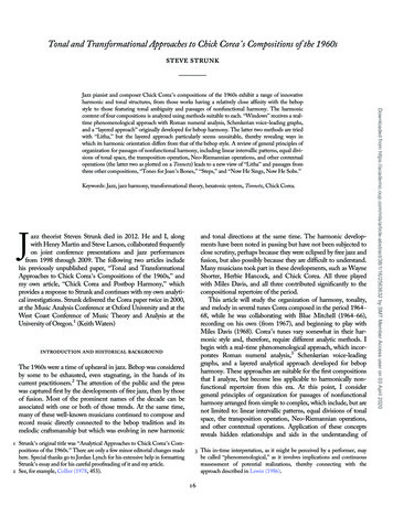
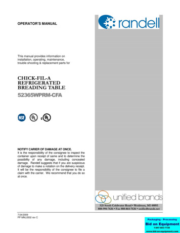
ReplacementPartsRefrigerated Breading TablesCAUTION: Hold lid with both hands securely at all times during opening and closing.18800-621-8560
unifiedbrands.net19
ITEMDESCRIPTIONPART #1Hinged Cover with Recessed HandleRP PCR05012Counter Balance Hinge Lift AssyHD HNG05013Adapter Grid, 12” x 20”RP ADP08014Drain Screen, 2”RP DSN0025Elbow, 1 ½” PVC Fem x GluePB ELB99056Pipe, 1 ½” PVCPB PIP1507Ball Valve, 1 ½” PVC FemalePB VLV99018Dixell Digital Control for BaseRP CNT02049Rocker On/Off Switch for RailEL SWT050210Dixell Digital Control for RailRP CNT050111Clean Condenser Indicator LightEL LGT030512Louver Knob, AluminumHD PIN010213Louver Door – TopRP LVR070713ALouver Door – BottomRP LVR070814Shelf Pins, AluminumHD PIN010215Shelf, 13-1/8” x 25-1/4” Stainless SteelHD SHL015SS16Door Hinge Top/BottomHD HNG070616ADoor Hinge Self Closure Spring (Bottom Only)HD HNG070717Toe Style Bracket/Door Handle, Stainless SteelRP HDL050118Door GasketIN GSK102019Evaporator Fan Motor, 120V w/bladeEL MTR233820800-621-8560
20Temperature Control Probe - DixellRF CNT050521Evaporator Condensate Pan, PlasticRP DRP10722Expansion ValveRF VLV40423Shield Panel for Base Coil AssemblyRP PNL10724Evaporator Coil AssemblyRP CSY108SL24AEvaporator CoilRF COI10725Solenoid ValveRF SOL980126Evaporator Fan ShroudRP SHD10727Mounting Support Bracket for Base Coil AssemblyRP SPT050028Door Assembly with Toe Bracket, Right HingeRP DOR070829Door Assembly with Toe Bracket, Left HingeRP DOR070730Caster, 4-1/2” Overall with locking mechanismHD CST03030ACaster, 4-1/2” Overall without locking mechanismHD CST03131Condensing Unit ShroudRP HSG050132Magnetic Catch & Bracket Assembly for Louver DoorRP CTH050133Magnetic CatchHD CTH990134Magnetic Catch PlateRP BRK050835Grease Filter, Condenser 9-1/2” x 11” Alum. w/pull handleHD FLT070136Condensing UnitRF CON990137Condenser Fan BladeRF FAN00738Condenser Fan MotorRF MTR0101P39CompressorRF CMP9902P4040W shatterproof light bulbEL LGT200unifiedbrands.net21
CHICK-FIL-A REFRIGERATED BREADING TABLE 52365WPRM-CFA NOTIFY CARIER OF DAMAGE AT ONCE. It is the responsibility of the consignee to inspect the container upon receipt of same and to determine the possibility of any damage, including concealed damage. Randell suggests that if you are suspicious