Transcription
NO2Orion 93-46,Orion 97-46, ionplus Orion NitriteElectrodeINSTRUCTION MANUALAnalyze Detect Measure Control
AQUAfast, Cahn, EZ Flash, Ionalyzer, ionplus, KNIpHE, No Cal, ORION, perpHect,PerpHecT, PerpHecTion, pHISA, pHix, pHuture, Pure Water, Sage, Sensing theFuture, SensorLink, ROSS Ultra, Sure-Flow, TEA Analyzer, Titrator PLUS, TURBO2and Wine Master are registered trademarks of Thermo Electron Corporation.1-888-pHAX-ION, A , All in One, Aplus, AQUAsnap, AssuredAccuracy,AUTO-BAR, AUTO-CAL, AUTO DISPENSER, Auto-ID, AUTO-LOG, AUTO-READ,AUTO-STIR, Auto-Test, BOD AutoEZ, Cable-Free, CERTI-CAL, CISA, DataCOLLECT,DataPLUS, digital LogR, DirectCal, DuraProbe, Environmental Product Authority,Extra Easy/Extra Value, FAST QC, Flash Titration, Flash Titrator, GAP, GLPcal,GLPcheck, GLPdoc, ISEasy, KAP, LabConnect, LogR, Low Maintenance Triode,Minimum Stir Requirement, MSR, NISS, One-Touch, One-Touch Calibration, OneTouch Measurement, Optimum Results, Pentrode, pHuture MMS, pHuturePentrode, pHuture Quatrode, pHuture Triode, Quatrode, QuiKcheK, rf link,ROSS, ROSS Resolution, SAOB, Smart CheK, Stacked, Stat Face, The EnhancedLab, ThermaSense, Triode, TRIUMpH, Unbreakable pH, Universal Access aretrademarks of Thermo.Guaranteed Success and The Technical Edge are service marks of Thermo.PerpHecT meters are protected by U.S. patent 6,168,707.PerpHecT ROSS are protected by U.S. patent 6,168,707.ORION Series A meters and 900A printer are protected by U.S. patents5,108,578, 5,198,093 and German patents D334,208 and D346,753.Sure-Flow electrodes are protected by European Patent 278,979and Canadian Patent 1,286,720.ionplus electrodes and Optimum Results solutions are protected byUS Patent 5,830,338.ROSS Ultra electrodes have patents pending.ORION ORP Standard is protected by US Patent 6,350,367.ORION Series A conductivity meters are protected by US Patent 5,872,454. Copyright 2003, Thermo Electron Corporation. All rights reserved. Questioneverything, and Analyze.Detect.Measure.Control are trademarks of ThermoElectron Corporation.The specifications, descriptions, drawings, ordering information and partnumbers within this document are subject to change without notice.This publication supersedes all previous publications on this subject.
TABLE OF CONTENTSGENERAL INFORMATIONIntroductionRequired EquipmentRequired SolutionsBEFORE USING THE ELECTRODEElectrode Assembly and PreparationOrion 93-46 Nitrite Half Cell ElectrodeOrion 90-02 Double Junction Reference ElectrodeOrion 97-46 ionplus Nitrite Combination ElectrodeChecking Electrode Operation (Slope)Recommendations for Optimum Results Units of MeasurementSample RequirementsImportant ISE Measurement TechniquesRoadway to ionplus Success!Guide to measuring techniquesMEASUREMENT PROCEDURESDirect MeasurementSmall Volume Direct MeasurementLow-Level Measurements By Direct MeasurementKnown Addition112355556101313131416161919253036ELECTRODE STORAGE46TROUBLESHOOTING48Troubleshooting ChecklistTroubleshooting GuideAssistanceELECTRODE CHARACTERISTICSElectrode ResponseLimits of DetectionReproducibilityTemperature EffectsInterferencesElectrode LifeChemistry of NitritepH EffectsTheory of ING INFORMATION69SPECIFICATIONS70
GENERAL INFORMATIONIntroductionThe Orion 93-46 Half-Cell and Orion 97-46 ionplus Nitrite Electrodesmeasure nitrite in aqueous solutions simply, accurately, andeconomically.The Orion 97-46 ionplus Nitrite Electrode offers additional benefitsfrom its Sure-Flow Combination reference design. With this electrode,a separate reference electrode is unnecessary, making it convenient touse with small sample volumes. The free-flowing Sure-Flow junctionassures stable, drift-free potentials. When measuring dirty samplesthat would clog conventional electrode junctions, the Sure-Flow junctioncan be cleaned by pressing the electrode cap.General analytical procedures, required solutions, electrodecharacteristics, and electrode theory are discussed in this manual.Operator instructions for Orion meters are outlined in the individualmeter’s instruction manual.Consult Technical Service Chemists for assistance and troubleshootingadvice. Please refer to Troubleshooting for information or contactingThermo Electron Corporation.1
Required EquipmentMeterISE meters, such as Orion EA 940, 920A, 920Aplus, 720A, 720Aplus,710A, 710Aplus, 290A, or 290Aplus, offering direct concentrationreadout for specific ions are the easiest to use. If unavailable, use apH/mV meter with readability to 0.1 mV, such as Orion 420A,420Aplus, 520A, 520Aplus, 525A or 525Aplus.Reference ElectrodeFor use with Orion 93-46:Orion 90-01 Single JunctionReference ElectrodeFor use with Orion 97-46:No separate reference electrode requiredOrion900100NAionplus Stirring Accessory or Stir Bars, and Magnetic StirrerStir bar or ionplus stirring accessory, Orion 900060 which slides overthe combination electrode body, to mix solution. Micro-stir bars arerecommended for small volume measurements.Graph Paper4 cycle semi-logarithmic paper for preparing calibration curves (foruse with digital pH/mV laboratory meters).2
Required SolutionsDistilled or Deionized WaterTo prepare all solutions and standards.Reference Electrode Filling SolutionRequired for a complete measuring systemFilling SolutionsOrionFor Orion 97-46 & Orion 90-01:Optimum Results F Filling Solution900046Note: Do not use the outer filling solution shipped with theOrion 90-01 reference electrode.Nitrite Stock Calibration StandardsTo prepare daily calibration solutions.Standards0.1 M Nitrite Concentration Standard100 ppm Nitrite as Nitrogen StandardTo prepare a 100 ppm Nitrite as Nitrogen standard,pipet 71.4 mL of the 0.1 M Nitrite standard,Orion 954606, into a 1 L volumetric flask,and dilute to volume with distilled water.Additional SolutionsNitrite Interference Suppressor Solution (NISS )Orion954606CustomerPreparedOrion934610For removal of a variety of interfering anions,including chloride ion, present in samples such asdrinking and waste water as well as to buffer thesolutions. See Interferences & pH EffectsNitrite Storage Solution (Mixture of 0.1 M NitriteConcentration Standard and NISS)Prepare by adding 0.1 mL of Orion 954606 and50 mL of Orion 934610 to a 100 mL volumetricflask and dilute to volume with distilled water.Alternately, store the nitrite electrode in thelowest concentration of nitrite standard withNISS that was used during calibration.CustomerPrepared3
4
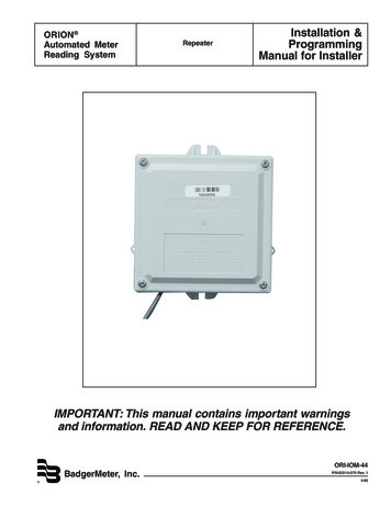
BEFORE USING THE ELECTRODEElectrode Assembly and PreparationOrion 93-46 Nitrite Half Cell Electrode:Remove the sensing module from the vial. Make sure the rubberelectrode washer on the sensing module is in place. See Figure 1.Screw the sensing module into the electrode body until finger tight.To ensure electrical continuity, shake down the electrode like a clinicalthermometer. The membrane surface should look dark andhomogeneous, with no bubbles on the inner surface. Rinse the nitriteelectrode with distilled water, then soak in Nitrite Storage Solution, seepage 3, for 1 to 2 hours prior to initial use. Do not immerse theelectrode past the rubber electrode washer. See Figure 1.electrode bodywashersensing modulesensing membraneFigure 1Orion 93-46 Electrode AssemblyOrion 90-01 Single Junction Reference Electrode:Required for use with Orion 93-46 Nitrite Half Cell Electrode. Fill thereference electrode according to instructions in the reference manual,using Optimum Results F, Orion 900046, instead of the FillingSolution provided with the electrode. Do not use the filling solutionshipped with the 90-01 reference electrode because it will interferewith your nitrite measurements.5
Orion 97-46 ionplus Nitrite Combination Electrode:This electrode consists of two parts, the sensing module and theelectrode handle. See Figure 2. The assembly is different than otherOrion electrodes.Be careful not to touch the sensing membrane or reference pelletduring assembly!capspringfill holeouter body sleeveinner stemreference pelletFigure 2Orion 97-46 ionplus NitriteCombination Electrode6O-ringssensing modulesensing membrane
1Remove the sensing module fromthe vial. Make sure both O-ringsare in place. Take the handle fromthe box.2Take the outer body sleeve, with thefill hole end towards the white cap,and gently push the inner stemthrough the outer body.3Slide the outer body sleeve, spring,and cap down the electrode cableuntil the outer body sleeve isbeyond the inner stem.4With one hand grasp the middle ofthe inner stem without touchingthe reference pellet. With yourother hand, screw the sensingmodule onto the stem until it stopsand the module is flush against thestem. Then tighten an additionalone-quarter turn and stop. Do notcontinue to over tighten. Themodule should be firmly attachedto the stem.5Holding the electrode cable, slidethe outer body, spring and cap overthe inner stem.6Grasp the outer body sleeve, do nottouch the sensing membrane.With your other hand, pull on thecable and gently screw the cap ontothe inner stem. Stop when anopposite force is felt. Do not overtighten or continue to turn the cap!The cap will not completely stop! Ifthe inner body turns at all, the capis too tight. Remove the cap andreassemble.7
7Hold the electrode with one hand.Press on the top of the cap withyour thumb to make sure theelectrode has a smooth flushingmotion and reseats back ontothe module.8Fill the outer body with OptimumResults F filling solution, Orion900046, to approximately 1/4 full.9Press cap to flush out the solution.Release the cap and ensure that theouter body sleeve returns to itsoriginal position.10Refill the electrode with OptimumResults F filling solution until thefluid level is just below the fill hole.8
11To ensure electrical continuity,grasp the outer body and cap andshake the sensing module endfirmly. Check to make sure themembrane surface is dark andhomogeneous with no bubbles onthe inner surface.Electrode reference filling solution should be added each day beforeuse. The filling solution should be no lower than 1 inch from the fillhole and must be above the reference pellet. The filling solution levelshould always remain 1 inch above the sample level to ensure properflow rate. Rinse the nitrite electrode with distilled water, then soak inNitrite Storage Solution, see page 3, for 1 to 2 hours prior to initial use.9
Checking Electrode Operation (Slope)Use these general instructions to check electrode operation. Seeindividual meter instruction manuals for more specific information.This procedure measures electrode slope. Slope is defined as thechange in millivolts observed with every tenfold (decade) change inconcentration. Obtaining the slope value provides the best means forchecking electrode operation.1If electrode(s) has been stored dry,prepare the electrode(s) as describedunder the section entitled ElectrodeAssembly and Preparation.2Connect electrode(s) to the meteras described in the meterinstruction manual.3Place 25 mL distilled water into a150 mL beaker. Add 25 mL NISS ,Orion 934610. Stir thoroughly.NISSISAsample10
4Set the meter to the mV mode.mV5Rinse electrode(s) with distilledwater, shake dry, and place in thesolution prepared in step 3 above.6Pipet 0.5 mL of the 100 ppm Nitriteas Nitrogen standard into thebeaker. Stir thoroughly.1.0 mLmL0.57When a stable reading is displayed,within 4 to 5 minutes, record theelectrode potential in millivolts.mV11
8Pipet 5.0 mL of the same standardinto the same beaker.Stir thoroughly.5.010.0mLmL9When a stable reading is displayed,with in 4 to 5 minutes, record theelectrode potential in millivolts.10The difference between the first andsecond potential reading is definedas the slope of the electrode. Thedifference should be in the range of-50 to -60 mV/decade when thesolution temperature is 25 5 C.If the slope is not within this range,resoak the electrode as describedunder the section entitled ElectrodeAssembly and Preparation.For other troubleshootingtechniques refer to theTroubleshooting section.12mV
Recommendations for Optimum Results Units of MeasurementMeasure nitrite in units of moles per liter, parts per million as nitrite,parts per million as nitrogen or any other convenient unit (see Table 1).Table 1Concentration Unit Conversion Factorsppm as NO2-ppm as N-44.601.4010-346.014.0460140moles per liter10-210Sample RequirementsSamples must be aqueous and must not contain organic solvents.Consult Technical Service Chemists for using the electrode in specificapplications.Sample temperature must be less than 40 C, with samples andstandards at the same temperature (within 0.5 C). At the 1.4 ppmas N or 10-4 M NO2- level, a 1 C difference in temperature producesabout a 2% error (Orion 93-46) and 0.5% error (Orion 97-46). Forhighly accurate results, use a water bath to control temperaturevariances.Dilute concentrated samples, those greater than 200 ppm as N or0.01 M NO2-, before analysis.Interferences not removed by the addition of NISS should be absent.See section entitled Interferences for a list of possible interferences.13
Important ISE Measurement Techniques Stir all standards and samples at a uniform rate during measurement.Magnetic stirrers may generate sufficient heat to change solutiontemperature. Place a piece of insulating material such as cork,cardboard or styrofoam between the stir plate and sample beaker. Always use fresh standards for calibration. Always rinse electrode(s) with distilled water thoroughly betweenmeasurements. Shake electrode after rinsing to prevent solutioncarryover. Do not wipe or rub the sensing membrane, as you maycontaminate and damage the surface. Store the electrode(s) in Nitrite Storage Solution (see RequiredSolutions) or in the lowest standard, containing NISS , betweenmeasurements. Allow all standards and samples to come to room temperature( 0.5 C) for precise measurements. After immersion in solution, check the nitrite electrode for any airbubbles on the membrane surface. Remove air bubbles at theelectrode surface by gently tapping the electrode. The Orion 93-46 Nitrite Half-Cell Electrode should be submergedapproximately half the length of the nitrite module. DO NOTsubmerge the nitrite electrode above the rubber electrodewasher. Submerge the reference electrode to the same depthas the nitrite electrode.14
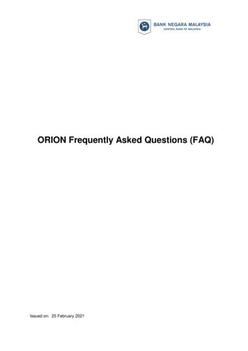
142563Figure 31. Ensure fill hole is not covered during measurement.2. Use fresh standard.3. Stir all samples and standards.4. Filling solution level must be higher than sample level, and at least1 inch above the reference pellet.5. Immerse reference junction.6. Place insulation between stirrer and beaker.NOTE: Do not submerge nitrite module past the rubber electrodewasher (Orion 93-46 only).15
Roadway to ionplus Success!Guide to measuring techniquesRecommendedConcentrationRangeLarge # ofsamplesDirectMeasurementSmall dition0.05 to 200ppm nitriteas N0.05 to 200ppm nitriteas N 0.5 ppmnitrite as N0.05 to 200ppm nitriteas NXX(Orion 97-46only)XSmall samplevolumeX(Orion 97-46only)Reducedchemical usageX(Orion 97-46only)FieldMeasurementsXXXX(Orion 97-46only)XIonic Strength 0.1 MXOccasionalsamplingXsee page #1618242935
A variety of analytical techniques are available to the analyst. The besttechnique is dependent upon the sample matrix. The following sectiondescribes the recommended techniques for nitrite determination.Direct Measurement is a simple procedure for measuring a largenumber of samples. This method requires only one meter reading foreach sample. Calibration is performed in a series of standards. Theconcentration of the samples is determined by comparison to thestandards. Addition of NISS to all solutions ensures that samplesand standards have similar ionic strength, proper pH, and reduces theeffect of interfering ions. When measuring small sample volumes orto reduce chemical usage, follow the Small Volume DirectMeasurement method, using the Orion 97-46 ionplusNitrite Electrode.Low-Level Measurement is similar to Direct Measurement. Use thismethod when the expected sample concentration is less than 0.5 ppmas N. Using a minimum of three calibration standards compensatesfor the electrode’s non-linear response at low concentrations. Thisprocedure describes the best means of preparing low-levelcalibration standards.Known Addition is an alternate method useful when measuring only afew samples, when samples have a high ( 0.1 M) ionic strength, orhave a complicated background matrix. Refer to Theory of Operationfor an explanation of these effects. The electrodes are immersed in thesample solution and an aliquot of a nitrite solution is added to thesample. From the change in potential before and after the addition, theoriginal sample concentration is determined. As in direct calibration,any convenient concentration unit can be used.17
18
MEASUREMENT PROCEDURESDirect MeasurementThe following direct measurement procedures are recommended for“high-level” measurements, when all samples fall within theelectrode’s linear range, greater than 0.5 ppm as N or 4 x 10⁻⁵ M NO2-.A two point calibration is sufficient, though more points can be used ifdesired. Using ISE meters, such as the Orion 920A, 920Aplus, 720A,720Aplus, 710A, 710Aplus, 290Aplus, or 290A, read sampleconcentrations directly from the meter. Refer to the meter’sinstruction manual for calibration details. When using a mV meter,prepare a calibration curve on semi-logarithmic graph paper, or alinear regression can be performed at the user’s discretion using aspreadsheet or graphing program.For Improved Accuracy Bracket standard concentrations around the expected sampleconcentration. Always dilute samples and standards in a 1:1 ratio with NISS . Forexample, 25 mL of sample and 25 mL of NISS. Verify direct measurement procedure by measuring a standard ofknown concentration as an unknown or by spiking a sample withnitrite standard. For high ionic strength, samples having an ionic strength of 0.1 M orgreater, prepare standards with a composition similar to that of thesamples, measure the samples using the known addition method, ordilute the samples. During calibration, measure the least concentrated standard first, andwork up to the most concentrated. The best method for preparation of standards is serial dilution. Thisprocedure involves preparing an initial standard that is diluted toprepare a second standard solution, using volumetric glassware.The second is similarly diluted to prepare a third standard, and soon, until the desired range of standards has been prepared. Review section entitled Important ISE Measurement Techniques.19
Direct Measurement Procedure using an ISE meter or a mV meterSee individual meter instruction manuals for more specificcalibration information.1Prepare the electrode(s) as describedin Electrode Assembly andPreparation.2Connect electrode(s) to the meter,and adjust the meter to measureconcentration for an ISE meter or mVfor a mV meter.3Prepare at least two standards thatbracket the expected sample rangeand differ in concentration by a factorof ten. Standards can be prepared inany concentration unit to suit theparticular analysis requirement. Allstandards should be at the sametemperature as the samples. Fordetails on temperature effects onelectrode performance, refer toTemperature Effects.x ppm10x ppm4Measure 50 mL of each standard andsample into separate 150 mL beakers.Add 50 mL of NISS to each standardand sample. NOTE: Other solutionvolumes may be used as long as theration of solution to NISS remains1:1. Stir thoroughly.20NISSISAsample
5For a ISE meter: Rinse electrode(s)with distilled water, shake dry, andplace into the beaker containing themost dilute standard. Wait for astable reading, calibrate the meterto display the value of the standardas described in the meterinstruction manual.DIFor a mV meter: Rinse electrode(s)with distilled water, shake dry, andplace into the beaker containing themost dilute standard. When astable reading is displayed, recordthe mV value and correspondingstandard concentration.6For a ISE meter: Rinse electrode(s)with distilled water, shake dry, andplace into the beaker with the nextstandard. Wait for a stable reading,then adjust the meter to displaythe value of the second standard,as described in the meterinstruction manual.For a mV meter: Rinse electrode(s)with distilled water, shake dry, andplace into the beaker containing thenext standard. When a stablereading is displayed, record themV value and correspondingstandard concentration.CALENTER21
7Repeat step 6 for all standards,working from the least concentratedto most concentrated standard.8For an ISE meter: Calibrationinformation will be calculated andstored automatically.For a mV meter: Using semilogarithmic graph paper, prepare acalibration curve by plotting themillivolt values on the linear axisand the standard concentrationvalues on the logarithmic axis.See Figure 4.22
9Rinse electrode(s) with distilledwater, shake dry, and placeinto sample.DI10For an ISE meter: When theelectrode stabilizes, the meter willdisplay the sample concentration.For a mV meter: When theelectrode stabilizes, the meter willdisplay the mV value for thesample. Using the calibrationcurve prepared in step 8, determinethe unknown sample concentration.RESULT23
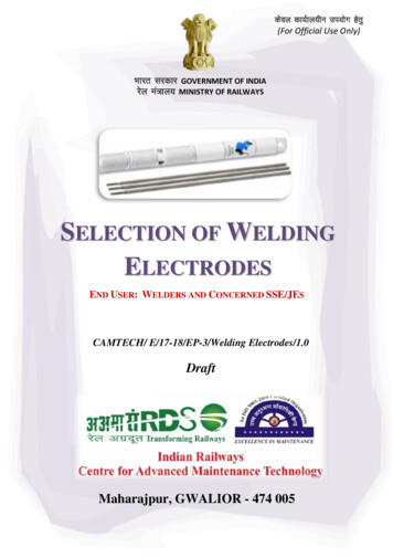
- 50electrodepotential(relative mV)- 2502510-fold change 5057 mV 75 100 125 150 175 200 225 250.01.1110-610-510-41010-310010-21000ppm NO2as Nmolarity10-1Figure 4Typical Nitrite Electrode Calibration CurveDuring the direct measurement procedure, a calibration curve isconstructed automatically by the ISE meter. Alternately, a calibrationcurve may be plotted by hand using semi-logarithmic paper.Measured electrode potentials of standard solutions are plotted on thelinear axis against their concentrations on the log axis. In the linearregions of the curves, only two standards are needed to determine acalibration curve. In non-linear regions, more points must be takenfor accuracy. The direct measurement procedures in the manual aregiven for concentrations in the region of linear electrode response.When measuring in the non-linear region follow the low-levelmeasurement procedure. This curve serves as an example only.Actual mV values may differ.24
Small Volume Direct Measurement (Orion 97-46ionplus Nitrite Electrode only)Using the Sure-Flow reference design, the Orion 97-46 ionplus NitriteElectrode allows measurement of sample volumes as small as 5 mLwith a modified direct measurement procedure. This technique isapplicable to any sample where reduced chemical usage of standardsand Nitrite Interference Suppressor Solution is important. This smallvolume measurement is well-suited for field testing as the combinationreference electrode conveniently reduces equipment, set-up andsampling time. All samples should be greater than 0.5 ppm as N or4 x 10-5 M NO2-. As with the previously described Direct Measurementprocedure, a two point calibration is sufficient, though more points canbe used if desired. Use a direct concentration meter (ISE meter) or apH/mV meter with 0.1 mV resolution. The following procedurerecommends using 10 mL of sample. Smaller sample volumes can beused, as long as the final volume of solution is sufficient to cover thereference junction of the Orion 97-46 electrode. Do not allow thesensing membrane to touch the sample container.For Improved Accuracy Use Orion 97-46 ionplus Nitrite Electrode. Bracket standard concentrations around the expected sampleconcentration. Always dilute samples and standards in a 1:1 ratio with NISS . Verify this procedure by measuring a standard of knownconcentration as an unknown or by spiking a sample with nitritestandard. For high ionic strength samples, having an ionic strength of 0.1 M orgreater, prepare standards with a composition similar to that of thesamples, measure the samples using the known addition method, ordilute the samples. During calibration, measure the least concentrated standard first, andwork up to the most concentrated. The best method for preparation of standards is serial dilution. Thisprocedure involves preparing an initial standard that is diluted toprepare a second standard solution, using volumetric glassware. Thesecond is similarly diluted to prepare a third standard, and so on,until the desired range of standards has been prepared. Review section entitled Important ISE Measurement Techniques.25
Small Volume Direct Measurement Procedure using an ISE meter ora mV meter and Orion 97-46 ionplus Nitrite ElectrodeSee individual meter instruction manuals for more specificcalibration information.1Prepare the Orion 97-46 ionplusNitrite Electrode as described inElectrode Assembly and Preparation.2Connect the electrode to the meter,and adjust the meter to measureconcentration for an ISE meter andmV for a mV meter.3Prepare at least two standards thatbracket the expected sample rangeand differ in concentration by a factorof ten. Standards can be prepared inany concentration unit to suit theparticular analysis requirement. Allstandards should be at the sametemperature as the samples. Fordetails on temperature effects onelectrode performance, refer toTemperature Effects.x ppm10x ppm4Measure 10 mL of each standard andsample into separate 150 mL beakers.Add 10 mL of NISS to each standardand sample.NOTE: Other solution volumes maybe used, as long as the ratio ofsolution to NISS remains 1:1.Stir thoroughly.26NISSISAsample
5For an ISE meter: Rinse Orion97-46 ionplus Nitrite Electrodewith distilled water, shake dry, andplace into the beaker containing themost dilute standard. Wait for astable reading, calibrate the meterto display the value of the standardas described in the meterinstruction manual.DIFor a mV meter: Rinse Orion97-46 ionplus Nitrite Electrodewith distilled water, shake dry, andplace into the beaker containing themost dilute standard. Wait for astable reading, record the mVvalue and correspondingstandard concentration.6For an ISE meter: Rinse Orion97-46 ionplus Nitrite Electrode withdistilled water, shake dry, and placeinto the beaker with the nextstandard. Wait for a stable reading,then adjust the meter to displaythe value of the second standard, asdescribed in the meter instructionmanual.For a mV meter: Rinse Orion97-46 ionplus Nitrite Electrode withdistilled water, shake dry, and placeinto the beaker containing the nextconcentrated standard. Wait for astable reading, record the mVvalue and correspondingstandard concentration.CALENTER27
7Repeat step 6 for all standards,working from the least concentratedto most concentrated standard.8For an ISE meter: Calibrationinformation will be calculated andstored automatically.For a mV meter: Using semilogarithmic graph paper, prepare acalibration curve by plotting themillivolt values on the linear axisand the standard concentrationvalues on the logarithmic axis.See Figure 4.28
9Rinse Orion 97-46 ionplus NitriteElectrode with distilled water, shakedry, and place into the sample.DI10For an ISE meter: When theelectrode stabilizes, the meter willdisplay the sample concentration.For a mV meter: When theelectrode stabilizes, the meter willdisplay the mV value for the sample.Using the calibration curve preparedin step 8, determine the unknownsample concentration.RESULT29
Low Level Measurements By Direct MeasurementUse this method when measuring solutions with a nitrite concentrationof less than 0.5 ppm as N or 4 x 10⁻⁵ M NO2-, those within thenon-linear range of the nitrite electrode. Low-level measurementsrequire at least three standards to compensate for the electrode’snon-linearity. Electrode response slows as the ions become moredilute.For Improved Accuracy If some samples have low-level concentrations, and some have higherconcentrations, dilute the higher concentrations down to the low-levelrange. The electrode’s time response at low-levels is faster, when it isnot also exposed to high concentrations. The choice of calibration standard concentrations is important forobtaining the best electrode performance and most rapid analysistime. Here are some guidelines:Ideally, calibration standard concentrations should bracket theexpected sample concentrations.If some samples have very low concentrations, for example less than0.1 ppm as N or 7 x 10⁻⁶ M NO2-, bracketing is not always practical.Generally, the lowest standard concentration should not be muchbelow 0.1 ppm as N or 7 x 10⁻⁶ M NO2-, since response time is slowat such low levels.The best results are obtained when the concentration of the highestcalibration standard is ten to one hundred times the lowest calibrationstandard concentration. Space additional standards equally withinthe range.If the expected sample concentrations fall within a narrow range (lessthan one order of magnitude), a ratio of highest to lowest standardconcentration of ten should be used.30
When measuring sub-ppm levels with Orion 920A, 720A, 710A, or290A, take advantage of the autoblank feature. It does not require azero standard, but can perform blank correction as long as the loweststandard concentration is in the non-linear range of the electrode.Electrodes are very slow in the absence of a measurable concentrationand a multipoint calibration generally will be less accurate when“zero” is included as a standard. Standard concentrations should bechosen such that the lowest standard value is larger than the blankvalue obtained, and the second lowest standard should be at leasttwice that of the lowest. See yourA-Series meter operations manual for additional information onblank correction.When not using an ISE meter, a calibration curve can be drawn onsemi-logarithmic graph paper or the data can be processed by meansof a spreadsheet or graphing program with a non-linear curvefitting feature.When using the Orion 920A, 920Aplus, 720A, 720Aplus, 710A,710Aplus,
that would clog conventional electrode junctions, the Sure-Flow junction can be cleaned by pressing the electrode cap. General analytical procedures, required solutions, electrode characteristics, and electrode theory are discussed in this manual. Operator instructions for Orion meters are outlined in the individual meter's instruction manual.