Transcription
Permeable Pavement Design TemplateMontgomery County RainScapesMontgomery County RainScapesResidential Permeable PavementWhat is permeable pavement?Permeable pavement is an attractive, watershed-friendly way to capture andclean stormwater runoff, and is an important part of Montgomery County’sRainScapes program. Permeable pavement is also a durable and environmentally sensitive alternative to conventional paving. Residential driveways thatare permeable help advance the goal of using innovative natural approaches toreduce water pollution, stream channel erosion, and drainage problems causedby stormwater runoff. These driveways also provide functional amenities forhomeowners.Permeable pavement driveways catch and soak in rain that falls on the drivewaysurface, reducing or eliminating driveway runoff that would otherwise flow to astorm drain. They may also be used to capture runoff from adjacent impervioussurfaces such as roofs, provided that the runoff does not have a high sedimentload. Rainwater rapidly passes through the pavement surface and collects in astone reservoir before soaking into the ground.This guide focuses on permeable interlocking concrete pavers (PICP), which are madeof high-strength solid concrete and have stone-filled openings that allow water topass. The design standards in this guide are intended for use by qualified contractorsin typical residential driveways and other small-scale installations generally pursuedthrough the RainScapes program. Residential driveways designed according to theseguidelines are intended for use by passenger vehicles, with occasional use by smalltrucks or moving vans.Permeable Pavement FAQsThis guide provides detail on these and other questions: How big can it be? Permeable pavement can be used to replace all or part of the driveway. How deep to dig? The excavation depth is 15 inches typically, and more in some cases. Where can permeable pavement be located? Driveways are the most common location, but sidewalks, parking lots,and patios are also possible. Homeowners may choose to install permeable pavement to replace all or only part of anexisting driveway. Is every site suitable for a permeable driveway? Some residential lots have challenges that go beyond the scope of thisguidance, such as slow-draining soils, high water tables, driveways that slope toward houses, or steep slopes, requiringsite-specific design by a professional. How is permeable pavement maintained? Residential permeable pavement driveways should be vacuumed with aheavy-duty wet/dry vacuum twice a year, usually in the spring and fall. Preventative maintenance is key to long-termperformance. Sand, sediment, and plant material (leaves, grass clippings, etc.) must be kept off the permeable surface. Is it ADA-accessible? Most interlocking pavers are ADA compliant. Paver manufacturers can provide information onspecific products. Why replace the driveway? In space-constrained lots that are too small for rain gardens, a permeable pavement driveway offers the best opportunity to capture and treat stormwater on site. The paver blocks also provide a unique andattractive design feature.
Permeable Pavement Design TemplateMontgomery County RainScapesWhere can permeable pavement go?LOCATIONWhen planning a permeable pavement driveway, follow the requirements listed in Table 1. If allthe requirements cannot be met, permeable pavement should not be installed at that location.Table 1. Required design elementsSetbackDistanceReasonFoundationA waterproof liner is required alongany portion of the driveway perimeter within 10 feet of a foundation(Figures 1, 2, and 3).Avoid possible water seepage intobasements. See construction step 4for detailsLimit of installationThe permeable portion of the driveway must end at the right-of-wayboundary (Figures 1, 2, and 3). Forvisual continuity, paver blocks with nosubsurface storage may be installedup to the edge of the sidewalk, apron,or curbline – check with County staff.Keep stormwater capture and treatment within private lots. Maintainconsistent appearance and conditionof sidewalks and driveway aprons.Conform with MCDOT ROW regulations.SlopesThe driveway slope should not exceed Minimize runoff and ensure adequateinfiltration into pavement surface5%. The driveway must slope awayfrom the house. Driveways that donot meet these criteria will need sitespecific design by a professional.TreesDo not disturb more than 25% of thecritical root zone for any trees witha diameter at breast height (DBH) ofeight inches or greater.Reduce potential negative treeimpacts from excavationUtilitiesMaintain a five-foot setback fromsanitary sewer or water mains. Neverinstall permeable pavement drivewaysover water, sewer, or gas mains. Lookfor private house connections.Reduce the chance of infiltration intoolder pipes. Prevent the drivewayfrom being disturbed if utility work isneeded.Water supply wellsMaintain a 100-foot setback from anywater supply well.Prevent infiltration into wellSeptic systemsMaintain a 50-foot setback from anyseptic system component.Prevent interference with septic system operation!Miss UtilityAlways call Miss Utility (811) before digging. Calling before deciding on a permeabledriveway design is recommended. Dig during the ticket timeframe, usually 10 days. It isadvisable to have the ticket on hand while digging. Look for private house connectionsbefore digging. Verification of utility locations is the contractor’s responsibility.2
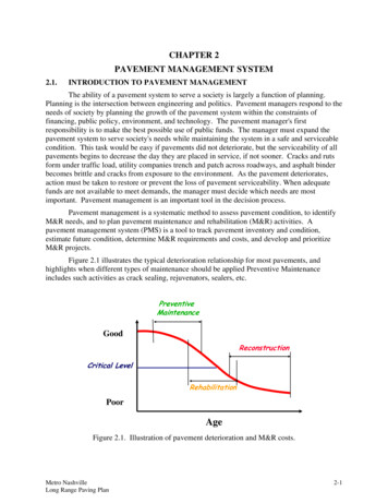
Permeable Pavement Design TemplateMontgomery County RainScapesFigure 1. Plan view of permeable pavement driveway installation5 ftFoundation5 ftRight-of-wayProperty lineSidewalkApronCurbStreetLegendInstall 5 foot wide perimeter liner if within10 feet of a foundation, including garagesPermeable pavement areaNon-permeable pavers in ROW(no storage). Obtain County approvalNotes:1. The driveway must slope away from the house.2. Do not disturb the sidewalk or driveway apron.3
Montgomery County RainScapesPermeable Pavement Design TemplateOther important guidelinesSAGSPermeable pavement should not be installed in driveways with a sag (low point)in the middle, unless the sag can be removed when reinstalling the driveway.DITCHES AND SWALESPermeable pavement is not recommended for driveways that receive concentrated flow from a ditch or swale because sediment deposition could occur. Inaddition, runoff from the ditch or swale could exceed the storage capacity of thepermeable driveway.UNPAVED AREASDo not install permeable pavement below areas with chronic erosion problemsunless the eroded area can be permanently stabilized first. To reduce the chanceof maintenance issues such as clogging, the amount of unpaved area draining tothe permeable driveway should generally be kept to a minimum.Non-typical applications,such as steep slopes,high water tables, andimpermeable soils requireconsultation with aqualified designer/engineer. Specific designguidance may also beobtained from theInterlocking ConcretePavement Institute(ICPI) and other relevantsources.DRIVEWAY APRONDo not use permeable pavement for the driveway apron. The driveway apron must be undisturbed or returned to its original condition to conform with Montgomery County right-of-way regulations.LONG DRIVEWAYSDriveways that are longer than 15 feet and have a slope greater than 2% may need additional design to prevent water fromaccumulating at the low end – consult a design professional.HEAVY VEHICLESDriveways designed according to these guidelines are not intended to support recurring loads from tractor trailers orgarbage trucks.4
Montgomery County RainScapesPermeable Pavement Design TemplateTesting the soilFor permeable pavement to function properly, water must be able to infiltrateinto the soil under the driveway. Use a simple test pit to estimate the soil infiltration rate below the driveway, following all steps below. Perform the test inthe late spring or fall, when the water content of soils may be higher. Avoid testing when the ground is frozen, very wet, or very dry.To avoid disturbing the existing pavement, dig a test pit in the yard adjacent tothe existing driveway. The test pit should be two feet from the driveway edgeand approximately one foot wide. It should also be located near the low point ofthe drive (but within the lot line) because water stored in the permeable driveway will generally migrate in that direction.The bottom of the test pit should match the bottom of the excavation becauseinfiltration into the existing soil will occur at that depth. The test pit depthwill typically be 15 inches, based on the typical dimensions of the followingcomponents, the most important of which is the reservoir depth. Refer to theSizing section for guidance on selecting the reservoir depth. Ensure that the testpit depth matches the dimensions for the actual design. Paver thickness (minimum 3⅛ inches) Bedding stone thickness (two inches recommended) Reservoir depth (typically 10 inches; see Sizing section)Carefully examine the soil horizon near the bottom of the test pit to check for ashallow clay layer. If a clay layer is present, the test pit can be excavated furtherto try to reach a less restrictive soil layer. However, the ultimate excavationdepth for the entire driveway should match the depth of the test pit. The depthof the driveway excavation will affect the cost of materials as well as disposal ofexcavated material.Depth to groundwaterIn low-lying areas, theseasonal high water tablemay be close to the surface.The bottom of the excavation must be 2 feet above theseasonal high water table toensure sufficient protectionfor groundwater.If a high water table issuspected, use a more specialized soil test, or request asoil map from the NaturalResources ConservationService or the Maryland-National Capital Park and Planning Commission.For more information visit:The Maryland NaturalResources ConservationServicewww.md.nrcs.usda.govThe Maryland-NationalCapital Park and PlanningCommissionwww.montgomeryplanning.orgThe Natural ResourceConservation Service WebSoil Surveyhttp://websoilsurvey.nrcs.usda.govAlways saturate the soil prior to conducting the test. Fill the hole to the topwith water. Let the water drain completely. Within twelve hours of draining,fill bottom six inches with water and start timing the drawdown period. If thedrawdown time exceeds 24 hours, permeable pavement is not recommendedwithout consulting a professional for a site-specific design. It may be possible tocapture driveway runoff in a rain garden.These design guidelines are based on the assumption of adequate subgrade bearing capacity under saturated conditions. If there are concerns about the bearingcapacity of the subgrade at the final excavation depth, contact a geotechnicalengineer or qualified professional for further soil evaluation (e.g., dynamic conepenetrometer test).5
Permeable Pavement Design TemplateMontgomery County RainScapesDesign guidelinesEDGE RESTRAINTSEdge restraints are essential to permeable driveway design and construction. Edge restraints must be present on all sidesof the driveway to provide a rigid perimeter that prevents pavers from shifting horizontally. Edge restraints also help toensure proper compaction of reservoir and bedding stone. Soil backfill is not an acceptable edge restraint.Four options for edge restraints are possible. Additional information is provided in Table 2 and in the construction sequence.1. A concrete curb, cast in place or precast, with a minimum four-inch width. The curb should extend at least nineinches below the finished driveway surface. This depth may include the thickness of a soldier or sailor course adheredto the top of the curb. The top of the curb may be below grade (recommended) or flush with the driveway surface(Figure 4).2. Metal or plastic strip edging. The edging must be designed for use with pavers. Do not use landscape edging. Theedging must be nailed into a dense-graded perimeter berm with a minimum top width of 12 inches (Figure 5).3. A cut pavement edge, at least five inches thick, adjacent to the permeable driveway. Thinner pavement sections are notacceptable edge restraints. This option applies mainly to the edge at the existing sidewalk, driveway apron, or roadway.4. The building foundation can also serve as an edge restraint, provided that the edge is straight, vertical, and at least fiveinches thick.Table 2. Allowable edge restraint configurationsEdge restraint typeBest location(s)Required excavationwidth beyond paveredge, each side (in.)CommentConcrete curbAll sides4-8Strip edgingLeft/right sides7-8Pavement edge FoundationDownslope end At house00May be preferable if drivewayedge abuts property line.Requires use ofdense-gradedberm for nailingstrips in place.Pavementthickness atcut edge mustbe at least fiveinches.See construction step4 for waterproofingmeasures near foundation.OVERFLOW DESIGNThe storage capacity of the permeable driveway may be exceeded by very heavy rainfall or storms in quick succession.Excess flow must be directed to a suitable location using one of the approaches below. Piped overflow – If grades allow, excess flow may be diverted into an overflow pipe connected to a pop-up drain inthe yard (Figures 2, 4, & 5; construction step 8). The feasibility of this option depends on elevations on the lot. Theoutflow pipe must have at least a 2% slope, and the rim of the pop-up drain must be at least 1½ inches lower than thetop of the overflow pipe at the upstream end. The pop-up drain should be located within the lot line, in a location thatprovides positive drainage away from structures and toward existing, stable flow paths, such as swales or the street. Thepop-up drain should generally be located at least two feet away from the driveway. Ensure that the pop-up drain willnot drain back onto the driveway or create a nuisance condition such as erosion or flow onto a neighboring lot. Alternately, the overflow pipe may connect to an adjacent storm drain or inlet if a pipe stub currently exists.6
Montgomery County RainScapesPermeable Pavement Design Template Surface overflow – If a piped overflow design is not feasible, the stone layers below the driveway may completely fillwith water during heavy rain. Excess flow will run off the driveway surface, much like a conventional driveway. Thestored water will draw down over time, and will also collect at the downslope end of the driveway. To reduce the potential for rutting at the downslope end, a waterproof liner and an additional layer of #2 stone must be installed in thisportion of the reservoir (Figure 3; construction step 6).SIZING PERMEABLE DRIVEWAYSA permeable pavement surface captures rainfall that falls directly on it. Homeowners can also look for opportunities toincrease runoff treatment by directing additional impervious area to the permeable driveway. Examples include rooftop,sidewalk, and non-permeable portions of the driveway. In order to ensure adequate performance and water quality treatment, the size of the additional contributing impervious area must be no more than five times the permeable pavementarea. This requirement does not change based on the depth of the reservoir stone.For example, if a homeowner installs 600 square feet of permeable pavement, up to 3,000 additional square feet of impervious area may be directed to the driveway. This may include paved areas that would naturally flow onto the permeablesurface, or roof runoff from a downspout. If the contributing impervious area is significantly larger than five times thepermeable pavement area, the permeable pavement area should be enlarged or the runoff should be partially or completelydirected away from the driveway. Runoff from contributing impervious areas should be free of sediment.In all cases, the permeable driveway must capture at least one inch of rain. If additional impervious area is directed to thedriveway, the reservoir depth may need to be increased to ensure at least one inch of rainfall capture (Tables 3-5).Typical permeable driveways with a 10-inch reservoir can captureapproximately 400 or more square feet of additional imperviousarea.LANDSCAPE DESIGN CONSIDERATIONS Installation of permeable pavement provides an opportunity to alter the driveway width. For instance, the drivewaycould be narrowed, with native vegetation planted along the edges. A variety of paver colors, shapes, and styles is available from different manufacturers. A soldier or sailor course can be laid along the edges of the driveway (Figure 4). Serving as a decorative border, soldieror sailor course pavers typically differ from those used in the rest of the driveway. Non-permeable pavers can be used.Soldier and sailor courses are laid perpendicular or parallel to the edge restraints, respectively, and the choice dependsprimarily on aesthetic preferences. Obtain several sample pavers before finalizing materials purchase.7
Permeable Pavement Design TemplateMontgomery County RainScapesThe amount of rainfall that can be captured and stored depends onthe permeable pavement area, the depth of the stone reservoir, andthe amount of additional impervious area that drains to the driveway.Tables 3-5 show rainfall capture for different reservoir depths. The recommended reservoir depth for most installations is 10 inches.The permeable pavement area is based on the extent of the stone reservoir. The permeable pavement area may not extend past the propertyline (Figure 1). Site-specific factors may reduce the available permeablepavement area.Residential permeable pavement driveways should be sized for 1.0 to2.5 inches of rain. The minimum rain capture goal for a RainScapesReward Rebate is 1.0 inch.Table 3. Rainfall capture for 10 inch reservoir.Inches ofrain storedPermeable pavement area (sq. ft.)Rainfall storage calculationAdditional impervious area (square .62.31.81.412003.22.92.72.41.91.6Table 4. Rainfall capture for 20 inch reservoir.3. Table 3 is the recommended starting point because it will meet therainfall capture goal in many cases while minimizing the excavationdepth.4. Across the top of the table, find the number closest to the additionalimpervious area (if any) that drains to the driveway, not including thedriveway itself. This may include roof and patio.5. Look down the column. Find the number closest to the desired rainfallstorage (at least 1.0 inch).6. Look to the left side of the table to find the corresponding permeablepavement area.7. If this permeable pavement area is larger than the available space,choose a smaller rainfall depth or repeat the process with a deeperreservoir.8. Make a note of the final stone reservoir depth and permeable pavementarea.Example: Use Table 3 for a design with a 10-inch reservoir. This table showsthat a permeable driveway with a 400 sq. ft. permeable pavement area and 200sq. ft. of additional impervious area can capture 2.1 inches of rainfall.Note: This rainfall capture calculation is conservative because it does not include drawdown into the underlying soil.Permeable pavement area (sq. ft.)2. Measure the additional impervious area (e.g., roof) that can be directedto the permeable driveway. The roof drainage area to each downspoutcan be found by dividing the house footprint by the number of downspouts. The additional contributing impervious area should be nomore than five times the permeable pavement area, as indicated by theblank cells in Tables 3-5.Inches ofrain storedAdditional impervious area (square .34.53.52.912006.35.85.44.73.83.2Table 5. Rainfall capture for 30 inch reservoir.Inches ofrain storedPermeable pavement area (sq. ft.)Using the rainfall storage tables1. Estimate the available permeable pavement area based on property linelocation, edge restraint width (Table 2), and other location guidelines.Additional impervious area (square .96.85.34.312009.58.78.17.15.74.78
Montgomery County RainScapesPermeable Pavement Design TemplateFigure 2. Profile view along driveway centerlinePermeable driveway with piped overflow9
Montgomery County RainScapesPermeable Pavement Design TemplateFigure 3. Profile view along driveway centerlinePermeable driveway with surface overflow10
Montgomery County RainScapesPermeable Pavement Design TemplateFigure 4. Cross-section at downslope end of drivewayPermeable driveway with concrete curb edge restraint and piped overflow11
Montgomery County RainScapesPermeable Pavement Design TemplateFigure 5. Cross-section at downslope end of drivewayPermeable driveway with strip edge restraint in dense-graded berm (DGB) and piped overflow12
Montgomery County RainScapesPermeable Pavement Design TemplateConstruction!Miss UtilityAlways call Miss Utility (811) before starting construction.STEP 1. GENERAL CONSTRUCTION GUIDELINESTo ensure long-term performance of permeable pavement driveways, it is critical to follow good construction practicesthat control sediment, divert runoff, and minimize soil compaction.a) Sequencing Install permeable pavement after any other site work has been completed. This will prevent accidental soil compaction and possible clogging from sediment. Do not install when the ground or stockpiled material is frozen or very wet. Spring or fall are best, when the groundhas a moderate amount of moisture.b) Soil protection All access for equipment, staging, and worker movement must have suitable ground protection. Acceptable methodsinclude a mulch access path, wooden mats, and HDPE mats, following County standards. During construction, avoid disturbing or compacting the surrounding soil as much as possible, especially aroundhealthy vegetation. Minimize the use of heavy equipment in the excavated area to avoid compacting the subsoil. Operate equipment atthe sides of the excavation if feasible, or over installed base materials (e.g., reservoir stone). As much as possible, avoid walking on disturbed areas until they have been stabilized with mulch or sod.c) Controlling runoff Secure a waterproof covering over any working surface during breaks in construction over eight hours, or if rain isimminent. Do not direct downspout flow to the driveway until permeable pavement installation is complete. Provide a splash pad in the driveway surface, if the downspout empties directly onto the pavement, in order to prevent joint washout. To control any remaining sources of sediment-laden runoff after the above measures have been taken, install temporary erosion control measures such as silt fences, temporary swales, or berms as appropriate.d) Stockpiling Stockpile reservoir stone as close to the excavation as possible, or deposit directly into the excavated area. Keep stone stockpile away from standing water and from sources of sediment and debris. Stockpiled stone should beplaced on pavement or geotextile to avoid sediment contamination. Do not use reservoir stone that is contaminated with sediment.Photo documentationTake photos to document all steps of the installation process to assist in rebate processing.Take photos of the basement before and after installation. Pay attention to any pre-existingwater damage and/or foundation damage.13
Montgomery County RainScapesPermeable Pavement Design TemplateSTEP 2. STAKEOUTa) Use stakes to mark the excavation area.b) The required excavation width is the sum of: Final driveway width desired Width needed for edge restraints on each side (Table 2)c) Offset stakes at least one foot outside the edge of the excavation to avoid disturbing stakes during construction.STEP 3. CLEARING AND EXCAVATIONa) Make a clean, straight saw cut in the existing pavement at all points where the pavers will touch existing pavement (e.g.,sidewalk). Use a saw and blade appropriate for the material being cut.b) Inspect the thickness of the cut pavement section. If the existing pavement is less than five inches thick, it cannot beused as an edge restraint, and a concrete curb must be installed (Step 9b). Cut additional pavement to accommodatecurbs as needed.c) Break up and remove the existing driveway with a jackhammer, sledgehammer and pry bar, or excavator blade.d) The required excavation depth is the sum of: Paver thickness (minimum 3⅛ inches) Bedding stone thickness (two inches recommended) Reservoir depth (typically 10 inches; see Sizing section)e) Excavate with mechanized equipment to the required width (Step 2) and depth. Hand dig within the dripline of anytrees 12 inches DBH (diameter at breast height) or greater.f) For designs with surface overflow, excavate an additional six-inch depth at the downslope end of the reservoir (Step 6;Figure 3).g) Take care to minimize root impacts during excavation. Prune roots one inch in diameter or larger as needed.h) If reservoir stone cannot be installed immediately after excavation, either: Excavate to the final depth, secure a waterproof covering over the excavation, and ensure that runoff does not enterfrom the sides; or Leave six inches of soil in place without a covering and excavate to the final depth just prior to installing the reservoir stone.i) If the subgrade at the desired depth is unstable, unconsolidated, or contains large rocks or debris, excavate until stablesubgrade is reached. Use #2 stone to fill the additional excavated volume and compact as described in Step 7. Do notuse soil as fill.14
Montgomery County RainScapesPermeable Pavement Design Templatej) The bottom of the excavation must slope away from the foundation and toward the street. A 1% slope is preferable,but up to 2% is allowed. This slope must be provided regardless of the finished slope of the driveway surface. If sitespecific conditions dictate that the bottom of the excavation has a slope greater than 2%, check dams may be needed toprevent water from accumulating at the low end – consult a design professional.k) The bottom of the excavation must not have a cross-slope that exceeds 0.5%.STEP 4. GEOTEXTILE AND WATERPROOF LINERa) Geotextile should be placed on all vertical sides of the excavation. Do not place geotextile on the bottom of the excavation or any other horizontal surface, except when installing waterproof liners as noted below.b) Avoid wrinkles and folds in all geotextile and liner installation, and overlap a minimum of 24 inches at joints. Securelyattach the geotextile and liner (if used) to the sides of the excavation following manufacturer specifications.c) A waterproof liner is required for any portion of the driveway perimeter within 10 feet of a foundation (Figures 1 - 3).Install geotextile as described above prior to installing the liner. The liner must extend vertically from the top of thepavers to the bottom of the excavation and then horizontally five feet away from the foundation.d) For designs with surface overflow, install a waterproof liner at the downslope end of the stone reservoir (Figure 3).Install geotextile as described above prior to installing the liner. The liner should extend vertically from the top of thepavers to the bottom of the excavation. Extend the liner horizontally one foot toward the house, following the bottomof the excavation and covering the entire excavated width.Note: Steps 5 and 6 discuss installation of optional stone layers, dependent on design decisionsregarding edge restraints and overflow. Although presented separately, both steps should occur inconjunction with the installation of reservoir stone (Step 7).STEP 5. DENSE-GRADED BERM (ALTERNATE TO STEP 9B)a) If strip edge restraints are used, the required dense-graded berm (DGB) must be installed at the same time as the reservoir stone (Step 7).b) Keep DGB material separate from the reservoir stone at all times.c) Geotextile must be placed between the reservoir stone and the DGB to prevent migration of fines. Key in geotextile under DGB before placing the first lift (Figure 5).d) The DGB and geotextile should slope toward the edges of the driveway at approximately 30%, or the angle of repose.e) Install and compact six-inch lifts of DGB in conjunction with the adjacent reservoir stone. After compaction, the topsof the DGB and reservoir stone must be even.15
Permeable Pavement Design TemplateMontgomery County RainScapesSTEP 6. SURFACE OVERFLOW (ALTERNATE TO STEP 8)a) Driveways with surface overflow require an additional six-inch layer of #2 stone below the reservoir. This area of additional #2 stone is three feet long, must span the full excavated width, and is located at the downslope end of the reservoir (Figure 3). The extra layer of stone provides additional stability.b) Prior to installing the reservoir stone (Step 7), place and compact the six-inch layer of #2 stone in the area described inStep 6a and shown in Figure 3.Observation wellPrior to installing reservoir stone, an observation well may be installed at the low end of the driveway at discretion of the owner or contractor (Figure 6).Figure 6. Observation well detailPaver surfaceScrew top lidPanella type cleanoutwith countersunk headPipe seal gasket4" dia. perforated PVCwrapped in geotextile16
Permeable Pavement Design TemplateMontgomery County RainScapesSTEP 7. RESERVOIR STONEa) Use a hoe, heavy-duty rake, or the backhoe bucket teeth to scarify (roughen) the top six inches of the existing soil at thebottom of the excavated area.b) The reservoir stone thickness is typically 10 inches but may be greater in some cases; see the Sizing section.c) Do not re-use any base course stone from the existing driveway. The reservoir stone must consist only of a bottomlayer of #2 s
tally sensitive alternative to conventional paving. Residential driveways that are permeable help advance the goal of using innovative natural approaches to reduce water pollution, stream channel erosion, and drainage problems caused by stormwater runoff . Th ese driveways also provide functional amenities for homeowners.