Transcription
Chapter 16NavigationIntroductionThis chapter provides an introduction to cross-countryflying under visual flight rules (VFR). It contains practicalinformation for planning and executing cross-country flightsfor the beginning pilot.Air navigation is the process of piloting an aircraft fromone geographic position to another while monitoring one’sposition as the flight progresses. It introduces the need forplanning, which includes plotting the course on an aeronauticalchart, selecting checkpoints, measuring distances, obtainingpertinent weather information, and computing flight time,headings, and fuel requirements. The methods used in thischapter include pilotage—navigating by reference to visiblelandmarks, dead reckoning—computations of direction anddistance from a known position, and radio navigation—byuse of radio aids.16-1
Aeronautical ChartsAn aeronautical chart is the road map for a pilot flying underVFR. The chart provides information that allows pilots to tracktheir position and provides available information that enhancessafety. The three aeronautical charts used by VFR pilots are: Sectional VFR Terminal Area World AeronauticalA free catalog listing aeronautical charts and relatedpublications including prices and instructions for ordering isavailable at the Aeronautical Navigation Products website:www.aeronav.faa.gov.Sectional ChartsSectional charts are the most common charts used by pilotstoday. The charts have a scale of 1:500,000 (1 inch 6.86nautical miles (NM) or approximately 8 statute miles (SM)),which allows for more detailed information to be includedon the chart.Figure 16-1. Sectional chart and legend.16-2The charts provide an abundance of information, includingairport data, navigational aids, airspace, and topography.Figure 16-1 is an excerpt from the legend of a sectionalchart. By referring to the chart legend, a pilot can interpretmost of the information on the chart. A pilot should alsocheck the chart for other legend information, which includesair traffic control (ATC) frequencies and information onairspace. These charts are revised semiannually except forsome areas outside the conterminous United States wherethey are revised annually.VFR Terminal Area ChartsVFR terminal area charts are helpful when flying in or nearClass B airspace. They have a scale of 1:250,000 (1 inch 3.43 NM or approximately 4 SM). These charts providea more detailed display of topographical information andare revised semiannually, except for several Alaskan andCaribbean charts. [Figure 16-2]World Aeronautical ChartsWorld aeronautical charts are designed to provide a standardseries of aeronautical charts, covering land areas of the world,
Figure 16-2. VFR Terminal Area Chart and legend.at a size and scale convenient for navigation by moderate speedaircraft. They are produced at a scale of 1:1,000,000 (1 inch 13.7 NM or approximately 16 SM). These charts are similar tosectional charts, and the symbols are the same except there isless detail due to the smaller scale. [Figure 16-3] These chartsare revised annually except several Alaskan charts and theMexican/Caribbean charts, which are revised every 2 years.Latitude and Longitude (Meridians andParallels)The equator is an imaginary circle equidistant from the polesof the Earth. Circles parallel to the equator (lines running eastand west) are parallels of latitude. They are used to measuredegrees of latitude north (N) or south (S) of the equator. Theangular distance from the equator to the pole is one-fourthof a circle or 90 . The 48 conterminous states of the UnitedStates are located between 25 and 49 N latitude. The arrowsin Figure 16-4 labeled “Latitude” point to lines of latitude.Meridians of longitude are drawn from the North Pole to theSouth Pole and are at right angles to the Equator. The “PrimeMeridian,” which passes through Greenwich, England, isused as the zero line from which measurements are made indegrees east (E) and west (W) to 180 . The 48 conterminousstates of the United States are between 67 and 125 Wlongitude. The arrows in Figure 16-4 labeled “Longitude”point to lines of longitude.Any specific geographical point can be located by referenceto its longitude and latitude. Washington, D.C., for example,is approximately 39 N latitude, 77 W longitude. Chicagois approximately 42 N latitude, 88 W longitude.Time ZonesThe meridians are also useful for designating time zones. Aday is defined as the time required for the Earth to make onecomplete rotation of 360 . Since the day is divided into 24hours, the Earth revolves at the rate of 15 an hour. Noon isthe time when the sun is directly above a meridian; to thewest of that meridian is morning, to the east is afternoon.16-3
Figure 16-3. World aeronautical chart.90 N75 N60 N5115nr idiameW W30 W45 W60 W7 5 W90 W105 W120 W13 5 W115500 WW15 Neri mP30 NLongitudedetituLa45 NE quator15 S30 S45 SThe standard practice is to establish a time zone for each15 of longitude. This makes a difference of exactly 1 hourbetween each zone. In the conterminous United States,there are four time zones. The time zones are Eastern (75 ),Central (90 ), Mountain (105 ), and Pacific (120 ). Thedividing lines are somewhat irregular because communitiesnear the boundaries often find it more convenient to use timedesignations of neighboring communities or trade centers.Figure 16-5 shows the time zones in the conterminous UnitedStates. When the sun is directly above the 90th meridian, itis noon Central Standard Time. At the same time, it is 1 p.m.Eastern Standard Time, 11 a.m. Mountain Standard Time,and 10 a.m. Pacific Standard Time. When Daylight SavingTime is in effect, generally between the second Sunday inMarch and the first Sunday in November, the sun is directlyabove the 75th meridian at noon, Central Daylight Time.60 SFigure 16-4. Meridians and parallels—the basis of measuring time,distance, and direction.16-4These time zone differences must be taken into accountduring long flights eastward—especially if the flight mustbe completed before dark. Remember, an hour is lost when
Pacific standard timeMountain standard timeCentral standard timeEastern standard time75 120 105 90 Figure 16-5. Time zones in the conterminous United States.flying eastward from one time zone to another, or perhapseven when flying from the western edge to the eastern edgeof the same time zone. Determine the time of sunset at thedestination by consulting the flight service station (FSS) andtake this into account when planning an eastbound flight.For Daylight Saving Time, 1 hour should be subtracted fromthe calculated times.In most aviation operations, time is expressed in terms ofthe 24-hour clock. ATC instructions, weather reports andbroadcasts, and estimated times of arrival are all based onthis system. For example: 9 a.m. is expressed as 0900, 1 p.m.is 1300, and 10 p.m. is 2200.Measurement of DirectionBy using the meridians, direction from one point to anothercan be measured in degrees, in a clockwise direction fromtrue north. To indicate a course to be followed in flight,draw a line on the chart from the point of departure to thedestination and measure the angle that this line forms witha meridian. Direction is expressed in degrees, as shown bythe compass rose in Figure 16-6.Because a pilot may cross several time zones during a flight, astandard time system has been adopted. It is called UniversalCoordinated Time (UTC) and is often referred to as Zulutime. UTC is the time at the 0 line of longitude which passesthrough Greenwich, England. All of the time zones aroundthe world are based on this reference. To convert to this time,a pilot should do the following:Because meridians converge toward the poles, coursemeasurement should be taken at a meridian near the midpointof the course rather than at the point of departure. The coursemeasured on the chart is known as the true course (TC). Thisis the direction measured by reference to a meridian or truenorth (TN). It is the direction of intended flight as measuredin degrees clockwise from TN.Eastern Standard Time.Add 5 hoursCentral Standard Time.Add 6 hoursMountain Standard Time.Add 7 hoursAs shown in Figure 16-7, the direction from A to B would bea TC of 065 , whereas the return trip (called the reciprocal)would be a TC of 245 .Pacific Standard Time.Add 8 hours16-5
N30The north magnetic pole is located close to 71 N latitude, 96 W longitude and is about 1,300 miles from the geographicor true north pole, as indicated in Figure 16-8. If the Earthwere uniformly magnetized, the compass needle would pointtoward the magnetic pole, in which case the variation betweenTN (as shown by the geographical meridians) and MN (asshown by the magnetic meridians) could be measured at anyintersection of the meridians.1518Figure 16-6. Compass rose.The true heading (TH) is the direction in which the nose ofthe aircraft points during a flight when measured in degreesclockwise from TN. Usually, it is necessary to head theaircraft in a direction slightly different from the TC to offsetthe effect of wind. Consequently, numerical value of the THmay not correspond with that of the TC. This is discussedmore fully in subsequent sections in this chapter. For thepurpose of this discussion, assume a no-wind condition existsunder which heading and course would coincide. Thus, fora TC of 065 , the TH would be 065 . To use the compassaccurately, however, corrections must be made for magneticvariation and compass deviation.VariationVariation is the angle between TN and magnetic north (MN).It is expressed as east variation or west variation dependingupon whether MN is to the east or west of TN.Course A to B 065 0 65 Actually, the Earth is not uniformly magnetized. In the UnitedStates, the needle usually points in the general direction ofthe magnetic pole, but it may vary in certain geographicallocalities by many degrees. Consequently, the exact amountof variation at thousands of selected locations in the UnitedStates has been carefully determined. The amount and thedirection of variation, which change slightly from timeto time, are shown on most aeronautical charts as brokenmagenta lines called isogonic lines that connect points ofequal magnetic variation. (The line connecting points atwhich there is no variation between TN and MN is the agonicline.) An isogonic chart is shown in Figure 16-9. Minorbends and turns in the isogonic and agonic lines are causedby unusual geological conditions affecting magnetic forcesin these areas.On the west coast of the United States, the compass needlepoints to the east of TN; on the east coast, the compass needlepoints to the west of TN.TNMNB 24 5ACourse B to A 245 Figure 16-7. Courses are determined by reference to meridians onaeronautical charts.16-6Figure 16-8. Magnetic meridians are in red while the lines oflongitude and latitude are in blue. From these lines of variation(magnetic meridians), one can determine the effect of local magneticvariations on a magnetic compass.
Easterly variationthis course off the magnetic compass would not provide anaccurate course between the two points due to three elementsthat must be considered. The first is magnetic variation, thesecond is compass deviation, and the third is wind correction.All three must be considered for accurate navigation.Westerly variationMagnetic VariationAs mentioned in the paragraph discussing variation, theappropriate variation for the geographical location ofthe flight must be considered and added or subtracted asappropriate. If flying across an area where the variationchanges, then the values must be applied along the route offlight appropriately. Once applied, this new course is calledthe magnetic course.Agonic lineMagnetic DeviationBecause each aircraft has its own internal effect upon theonboard compass systems from its own localized magneticinfluencers, the pilot must add or subtract these influencersbased upon the direction he or she is flying. The application ofdeviation (taken from a compass deviation card) compensatesthe magnetic course unique to that aircraft’s compass system(as affected by localized magnetic influencers) and it nowbecomes the compass course. Therefore, the compass course,when followed (in a no wind condition), takes the aircraftfrom point A to point B even though the aircraft headingmay not match the original course line drawn on the chart.Figure 16-9. Note the agonic line where magnetic variation is zero.Zero degree variation exists on the agonic line whereMN and TN coincide. This line runs roughly west of theGreat Lakes, south through Wisconsin, Illinois, westernTennessee, and along the border of Mississippi and Alabama.Compare Figures 16-9 and 16-10.Because courses are measured in reference to geographicalmeridians that point toward TN, and these courses aremaintained by reference to the compass that points along amagnetic meridian in the general direction of MN, the truedirection must be converted into magnetic direction for thepurpose of flight. This conversion is made by adding orsubtracting the variation indicated by the nearest isogonicline on the chart.If the variation is shown as “9 E,” this means that MN is9 east of TN. If a TC of 360 is to be flown, 9 must besubtracted from 360 , which results in a magnetic headingof 351 . To fly east, a magnetic course of 081 (090 – 9 )would be flown. To fly south, the magnetic course would be171 (180 – 9 ). To fly west, it would be 261 (270 – 9 ).To fly a TH of 060 , a magnetic course of 051 (060 – 9 )would be flown.For example, a line drawn between two points on a chartis called a TC as it is measured from TN. However, flyingNPEvaria astio tnNPNPMPMPMPtnesiatioW 24211530WWS3030212115S15SPFigure 16-10. Effect of variation on the compass.16-7
Remember, if variation is west, add; if east, subtract. Onemethod for remembering whether to add or subtract variationis the phrase “east is least (subtract) and west is best (add).”DeviationDetermining the magnetic heading is an intermediate stepnecessary to obtain the correct compass heading for the flight.To determine compass heading, a correction for deviationmust be made. Because of magnetic influences within anaircraft, such as electrical circuits, radio, lights, tools, engine,and magnetized metal parts, the compass needle is frequentlydeflected from its normal reading. This deflection is calleddeviation. The deviation is different for each aircraft, andit also may vary for different headings in the same aircraft.For instance, if magnetism in the engine attracts the northend of the compass, there would be no effect when the planeis on a heading of MN. On easterly or westerly headings,however, the compass indications would be in error, as shownin Figure 16-11. Magnetic attraction can come from manyother parts of the aircraft; the assumption of attraction in theengine is merely used for the purpose of illustration.Some adjustment of the compass, referred to as compensation,can be made to reduce this error, but the remaining correctionmust be applied by the pilot.Proper compensation of the compass is best performed bya competent technician. Since the magnetic forces withinthe aircraft change because of landing shocks, vibration,mechanical work, or changes in equipment, the pilot shouldoccasionally have the deviation of the compass checked. Theprocedure used to check the deviation is called “swinging thecompass” and is briefly outlined as follows.Magnetic NorthMagnetic NorthMagnetic 212115S15Magnetized engineFigure 16-11. Magnetized portions of the airplane cause thecompass to deviate from its normal indications.16-8The aircraft is placed on a magnetic compass rose, the enginestarted, and electrical devices normally used (such as radio)are turned on. Tailwheel-type aircraft should be jacked up intoflying position. The aircraft is aligned with MN indicated onthe compass rose and the reading shown on the compass isrecorded on a deviation card. The aircraft is then aligned at30 intervals and each reading is recorded. If the aircraft is tobe flown at night, the lights are turned on and any significantchanges in the readings are noted. If so, additional entriesare made for use at night. The accuracy of the compass canalso be checked by comparing the compass reading with theknown runway headings.A deviation card, similar to Figure 16-12, is mounted nearthe compass showing the addition or subtraction required tocorrect for deviation on various headings, usually at intervalsof 30 . For intermediate readings, the pilot should be able tointerpolate mentally with sufficient accuracy. For example,if the pilot needed the correction for 195 and noted thecorrection for 180 to be 0 and for 210 to be 2 , it couldbe assumed that the correction for 195 would be 1 . Themagnetic heading, when corrected for deviation, is knownas compass heading.Effect of WindThe preceding discussion explained how to measure a TCon the aeronautical chart and how to make corrections forvariation and deviation, but one important factor has notbeen considered—wind. As discussed in the study of theatmosphere, wind is a mass of air moving over the surface ofthe Earth in a definite direction. When the wind is blowingfrom the north at 25 knots, it simply means that air is movingsouthward over the Earth’s surface at the rate of 25 NM in1 hour.Under these conditions, any inert object free from contactwith the Earth is carried 25 NM southward in 1 hour. Thiseffect becomes apparent when such things as clouds, dust,and toy balloons are observed being blown along by the wind.Obviously, an aircraft flying within the moving mass of airis similarly affected. Even though the aircraft does not floatfreely with the wind, it moves through the air at the sametime the air is moving over the ground, and thus is affectedby wind. Consequently, at the end of 1 hour of flight, theaircraft is in a position that results from a combination ofthe following two motions:For (Magnetic)Steer (Compass)N030286057E86120117150148For (MagneticSteer (Compass)S180210212240243W274300303330332Figure 16-12. Compass deviation card.
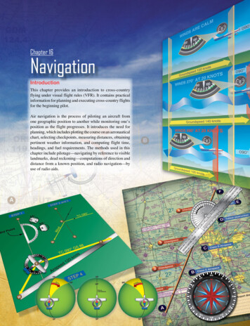
Movement of the air mass in reference to the ground Forward movement of the aircraft through the air massActually, these two motions are independent. It makes nodifference whether the mass of air through which the aircraftis flying is moving or is stationary. A pilot flying in a 70knot gale would be totally unaware of any wind (except forpossible turbulence) unless the ground were observed. Inreference to the ground, however, the aircraft would appearto fly faster with a tailwind or slower with a headwind, or todrift right or left with a crosswind.As shown in Figure 16-13, an aircraft flying eastward atan airspeed of 120 knots in still air has a groundspeed (GS)exactly the same—120 knots. If the mass of air is movingeastward at 20 knots, the airspeed of the aircraft is notaffected, but the progress of the aircraft over the ground is120 plus 20 or a GS of 140 knots. On the other hand, if theWINDS ARE CALM090 Groundspeed 120 knotsWINDS 270 AT 20 KNOTS090 Groundspeed 140 knotsWINDS 090 AT 20 KNOTS090 mass of air is moving westward at 20 knots, the airspeed ofthe aircraft remains the same, but GS becomes 120 minus20 or 100 knots.Assuming no correction is made for wind effect, if an aircraftis heading eastward at 120 knots and the air mass movingsouthward at 20 knots, the aircraft at the end of 1 hour isalmost 120 miles east of its point of departure because of itsprogress through the air. It is 20 miles south because of themotion of the air. Under these circumstances, the airspeedremains 120 knots, but the GS is determined by combiningthe movement of the aircraft with that of the air mass. GS canbe measured as the distance from the point of departure tothe position of the aircraft at the end of 1 hour. The GS canbe computed by the time required to fly between two points aknown distance apart. It also can be determined before flightby constructing a wind triangle, which is explained later inthis chapter. [Figure 16-14]The direction in which the aircraft is pointing as it flies iscalled heading. Its actual path over the ground, which is acombination of the motion of the aircraft and the motion ofthe air, is called track. The angle between the heading andthe track is called drift angle. If the aircraft heading coincideswith the TC and the wind is blowing from the left, the trackdoes not coincide with the TC. The wind causes the aircraftto drift to the right, so the track falls to the right of the desiredcourse or TC. [Figure 16-15]The following method is used by many pilots to determinecompass heading: after the TC is measured, and windcorrection applied resulting in a TH, the sequence TH variation (V) magnetic heading (MH) deviation (D) compass heading (CH) is followed to arrive at compassheading. [Figure 16-16]By determining the amount of drift, the pilot can counteractthe effect of the wind and make the track of the aircraftcoincide with the desired course. If the mass of air is movingacross the course from the left, the aircraft drifts to theright, and a correction must be made by heading the aircraftsufficiently to the left to offset this drift. In other words, ifthe wind is from the left, the correction is made by pointingthe aircraft to the left a certain number of degrees, thereforecorrecting for wind drift. This is the wind correction angle(WCA) and is expressed in terms of degrees right or left ofthe TC. [Figure 16-17]Groundspeed 100 knotsFigure 16-13. Motion of the air affects the speed with which aircraftmove over the Earth’s surface. Airspeed, the rate at which anaircraft moves through the air, is not affected by air motion.16-9
Distancecovered over groun20 knotsAirspeed effect (1 hour)d (1hour)WindFigure 16-14. Aircraft flight path resulting from its airspeed and direction and the wind speed and direction.HeadingDesired courseDrift angleTrackFigure 16-15. Effects of wind drift on maintaining desired course.To summarize:MN CN Course—intended path of an aircraft over the groundor the direction of a line drawn on a chart representingthe intended aircraft path, expressed as the anglemeasured from a specific reference datum clockwisefrom 0 through 360 to the line. Heading—direction in which the nose of the aircraftpoints during flight. Track—actual path made over the ground in flight. (Ifproper correction has been made for the wind, trackand course are identical.) Drift angle—angle between heading and track. WCA—correction applied to the course to establisha heading so that track coincides with course. Airspeed—rate of the aircraft’s progress throughthe air. GS—rate of the aircraft’s inflight progress overthe ground.DEV 4 TNCH-0 88VAR 10 E78 TH-074 MH-0HeadingFigure 16-16. Relationship between true, magnetic, and compassheadings for a particular instance.16-10
Wind075dingHeaWindcorrectionangleTrackDesired course090 Figure 16-17. Establishing a wind correction angle that counteracts wind drift and maintains the desired course.Basic CalculationsBefore a cross-country flight, a pilot should make commoncalculations for time, speed, and distance, and the amountof fuel required.Converting Minutes to Equivalent HoursFrequently, it is necessary to convert minutes into equivalenthours when solving speed, time, and distance problems. Toconvert minutes to hours, divide by 60 (60 minutes 1 hour).Thus, 30 minutes is 30/60 0.5 hour. To convert hours tominutes, multiply by 60. Thus, 0.75 hour equals 0.75 60 45 minutes.Time T D/GSTo find the time (T) in flight, divide the distance (D) by theGS. The time to fly 210 NM at a GS of 140 knots is 210 140 or 1.5 hours. (The 0.5 hour multiplied by 60 minutesequals 30 minutes.) Answer: 1:30.Distance D GS X TTo find the distance flown in a given time, multiply GS bytime. The distance flown in 1 hour 45 minutes at a GS of 120knots is 120 1.75 or 210 NM.GS GS D/TTo find the GS, divide the distance flown by the timerequired. If an aircraft flies 270 NM in 3 hours, the GS is270 3 90 knots.Converting Knots to Miles Per HourAnother conversion is that of changing knots to miles per hour(mph). The aviation industry is using knots more frequentlythan mph, but is important to understand the conversion forthose that use mph when working with speed problems. TheNWS reports both surface winds and winds aloft in knots.However, airspeed indicators in some aircraft are calibratedin mph (although many are now calibrated in both mph andknots). Pilots, therefore, should learn to convert wind speedsthat are reported in knots to mph.A knot is 1 nautical mile per hour (NMPH). Because there are6,076.1 feet in 1 NM and 5,280 feet in 1 SM, the conversionfactor is 1.15. To convert knots to mph, multiply speed inknots by 1.15. For example: a wind speed of 20 knots isequivalent to 23 mph.Most flight computers or electronic calculators have ameans of making this conversion. Another quick method ofconversion is to use the scales of NM and SM at the bottomof aeronautical charts.Fuel ConsumptionTo ensure that sufficient fuel is available for your intendedflight, you must be able to accurately compute aircraft fuelconsumption during preflight planning. Typically, fuelconsumption in gasoline-fueled aircraft is measured ingallons per hour. Since turbine engines consume much morefuel than reciprocating engines, turbine-powered aircraftrequire much more fuel, and thus much larger fuel tanks.When determining these large fuel quantities, using a volumemeasurement such as gallons presents a problem becausethe volume of fuel varies greatly in relation to temperature.In contrast, density (weight) is less affected by temperatureand therefore, provides a more uniform and repeatablemeasurement. For this reason, jet fuel is generally quantifiedby its density and volume.This standard industry convention yields a pounds-of-fuelper-hour value which, when divided into the nautical miles(NM) per hour of travel (TAS winds) value, results in aspecific range value. The typical label for specific range isNM per pound of fuel, or often NM per 1,000 pounds of fuel.Preflight planning should be supported by proper monitoringof past fuel consumption as well as use of specified fuelmanagement and mixture adjustment procedures in flight.16-11
For simple aircraft with reciprocating engines, the AircraftFlight Manual/Pilot’s Operating Handbook (AFM/POH)supplied by the aircraft manufacturer provides gallons-perhour values to assist with preflight planning.When planning a flight, you must determine how muchfuel is needed to reach your destination by calculating thedistance the aircraft can travel (with winds considered) ata known rate of fuel consumption (gal/hr or lbs/hr) for theexpected groundspeed (GS) and ensure this amount, plus anadequate reserve, is available on board. GS determines thetime the flight will take. The amount of fuel needed for agiven flight can be calculated by multiplying the estimatedflight time by the rate of consumption. For example, a flightof 400 NM at 100 knots GS takes 4 hours to complete. If anaircraft consumes 5 gallons of fuel per hour, the total fuelconsumption is 20 gallons (4 hours times 5 gallons). In thisexample, there is no wind; therefore, true airspeed (TAS)is also 100 knots, the same as GS. Since the rate of fuelconsumption remains relatively constant at a given TAS,you must use GS to calculate fuel consumption when windis present. Specific range (NM/lb or NM/gal) is also usefulin calculating fuel consumption when wind is a factor.You should always plan to be on the surface before any ofthe following occur: Your flight time exceeds the amount of flight timeyou calculated for the consumption of your preflightfuel amount Your fuel gauge indicates low fuel levelThe rate of fuel consumption depends on many factors:condition of the engine, propeller/rotor pitch, propeller/rotor revolutions per minute (rpm), richness of the mixture,and the percentage of horsepower used for flight at cruisingspeed. The pilot should know the approximate consumptionrate from cruise performance charts or from experience.In addition to the amount of fuel required for the flight,there should be sufficient fuel for reserve. When estimatingconsumption you must plan for cruise flight as well as startupand taxi, and higher fuel burn during climb. Remember thatground speed during climb is less than during cruise flightat the same airspeed. Additional fuel for adequate reserveshould also be added as a safety measure.Flight ComputersUp to this point, only mathematical formulas have been usedto determine such items as time, distance, speed, and fuelconsumption. In reality, most pilots use a mechanical flightcomputer called an E6B or electronic flight calculator. Thesedevices can compute numerous problems associated withflight planning and navigation. The mechanical or electronic16-12computer has an instruction book that probably includessample problems so the pilot can become familiar with itsfunctions and operation. [Figure 16-18]PlotterAnother aid in flight planning is a plotter, which is a protractorand ruler. The pilot can use this when determining TC andmeasuring distance. Most plotters have a ruler that measuresin both NM and SM and has a scale for a sectional chart on oneside and a world aeronautical chart on the other. [Figure 16-18]PilotagePilotage is navigation by reference to landmarks orcheckpoints. It is a method of navigation that can be usedon any course that has adequate checkpoints, but it is morecommonly used in conjunction with dead reckoning andVFR radio navigation.The checkpoints selected should be prominent featurescommon to the area of the flight. Choose checkpoints that canbe readily identified by other features,
13.7 NM or approximately 16 SM). These charts are similar to sectional charts, and the symbols are the same except there is less detail due to the smaller scale. [Figure 16-3] These charts are revised annually except several Alaskan charts and the Mexican/Caribbean charts, which are revised every 2 years. Latitude and Longitude (Meridians and