Transcription
ConfigurationandmanagementofNetworks2012LAB 1 –Exercise 1- Subnetting exercises.Write the subnet, broadcast address, and valid host range for question 1 through question 6:1. 192.168.100.25/302. 192.168.100.37/283. 192.168.100.66/274. 192.168.100.17/295. 192.168.100.99/266. 192.168.100.99/257. You have a Class B network and need 29 subnets. What is your mask?8. What is the broadcast address of 192.168.192.10/29?9. How many hosts are available with a Class C /29 mask?10. What is the subnet for host ID 10.16.3.65/23?Given a Class B network and the net bits identified (CIDR), complete the following table toidentify the subnet mask and the number of host addresses possible for each mask.Classful 30Subnet Mask255.255.0.0Number of Hosts per Subnet (2x – 2)65,534Complete the following tableIP ClassANº Subnet and Host Bits15 / 9Nº Subnets32768Nº Hosts510
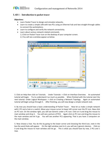
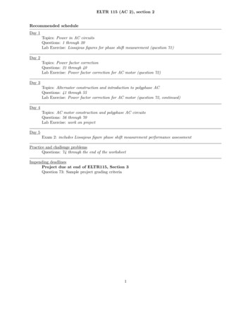
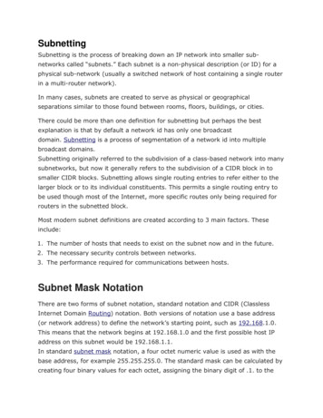
ICS432: Computer Network Systems Dr. Fazal NoorComputer Science and Software Eng. Dept.Lab Instructor: Tuwailaa AlshammariofNetworks2012University of HailConfigurationandmanagementStudentID:Exercise 2 – Introduction to packet tracerLAB 1: Introduction to Packet Tracer and Simple 2 PC network.ICS432: Computer Network Systems Dr. Fazal t.LearnPacketto Eng.designand simulate networks. Lab Instructor: Tuwailaa AlshammariUniversityof HailStudenthubID: and two straight through cablesLearnto create a simple LAN with two PCs using an Ethernetto connect the workstations.Learn to configure and verify the network connectivity.LABvarious1: Introductionto PacketTracer and Simple 2 PC network.Learn aboutnetwork relatedcommands.Objectives:1.) Click on Packet Tracer Icon on the desktop of your computer screen.LearnTracerto designandassimulate2.)YouPacketwill seea windowappearbelow. networks.Learn to create a simple LAN with two PCs using an Ethernet hub and two straight through cablesto connect the workstations.Learn to configure and verify the network connectivity.Learn about various network related commands.1.) Click on Packet Tracer Icon on the desktop of your computer screen.2.) You will see a window appear as below.3. Click on Help then click on Tutorials. Under Tutorials Click on Interface Overview. An automatedtutorial will begin. Try to understand it as much as possible. When finished with the tutorial start thenext tutorial. Under Logical Workspace click on Creating a Network Topology. Again an automatedtutorial will begin and go through it. After finishing, you will now design a simple network next.4. By now you should have a basic understanding of Packet Tracer. Now let us make a simple networkloweronleftcorner Overview.over the PC icon.Now clickwith2 PCa huba switch.Move yourmousecursor to3. ClickonandHelpthenorclickon Tutorials.UnderTutorials ClickInterfaceAn automatedonPC icon.the windowright, you willseeGenericunder a PCicon.finishedClick onwithit anddragthe mousetotutorialwill Onbegin.Try to understandit asmuchas possible.Whenthetutorialstart themainwindow Underand dropit. Youwill see a picturePCO. Againclick onPC icon anddragantheautomatedmouse tonext tutorial.LogicalWorkspaceclick onofCreatinga NetworkTopology.Againthemainwillwindowand goletthroughit go. it.You Afterwill seeanotherPC1Thatis younetworkhave 2 computersontutorialbegin andfinishing,youwillappearing.now designa simplenext.the main window.4. By now you should have a basic understanding of Packet Tracer. Now let us make a simple network5.Nowchoosehub.do thisby goingto the lowerandthe thirdtheleftchoosingcorner overthe PCicon,icon.noteNowinclickwith2 PCand a ahuborYoua switch.Moveyour mousecursorcornerto lowerboxtheicon.wordappear.next toait,willClicksee on2 genericdevices.Click onon PCOnHubsthe willwindowright, Onyouthewillrightsee windowGeneric underPCyouicon.it and dragthe mousetoitmainandwindowdrag theandmouselet go.This isAgainwhat clickyou onshouldhavebydragnow,the2 PCsandto1drop toit. mainYouwindowwill see anda pictureof PCO.PC iconandmouseHub.the main window and let it go. You will see another PC1 appearing. That is you have 2 computers onthe main window. Dr.Noor5. Now choose a hub. You do this by going totheFazallowercorner and choosing the third icon, note in thebox the word Hubs will appear. On therightwindownextto it, you will see 2 generic devices. Click on3http://faculty.uoh.edu.sa/f.noor/it and drag the mouse to main window and let go. This is what you should have by now, 2 PCs and 1Hub. Dr. Fazal Noorhttp://faculty.uoh.edu.sa/f.noor/3
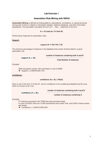
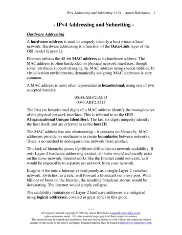
ConfigurationandmanagementofNetworks2012Nowwewe wantwant toto connectconnect thethe5th5thicon(zig(zigzagzagorangein color)clickclick6.6.Nowthe rnertheiconorangein color)on it and in box the word connections will appear. Now on the window on right you will see differenton it and in box the word connections will appear. Now on the window on right you will see differenttypes of cables appearing. Choose the third on “Copper Straight Through”. Click on this cable and drag ittypes of cables appearing. Choose the third on “Copper Straight Through”. Click on this cable and drag itto the PCO and to the Hub. You will see ports with numbers you may connect to anyone. Again repeattobetweenthe PCOPC1andto the Hub. You will see ports with numbers you may connect to anyone. Again repeatand the Hub. This is what you should have by now.between PC1 and the Hub. This is what you should have by now.ICS432:Computer Dr.NoorFast double7. Nowthat weNetworkhave theSystemssimple network, we need to assign IP addresses totheFazal2 PCs.Computer Science and Software Eng. Dept. Lab Instructor: Tuwailaa Alshammari7. Now thatwe have the simple network, weneedassign StudentIP addresses Dr.FazaltoNoorUniversityof HailID: to the 2 PCs. Fast doubleclick on PC0. You will get pop up windowofPCO and click on “Config” menu to get the window below.4http://faculty.uoh.edu.sa/f.noor/Fazal Noor and for subnet mask type 255.255.255.0.Click on Fastethernet. In the IP Address type Dr.in 192.168.7.5Click on X to close this box afterwards.http://faculty.uoh.edu.sa/f.noor/48. Similarily do with PC1 but assign the following IP address 192.168.7.10 and subnet mask 255.255.255.0Click on X to close the sub window.
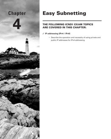
ICS432: Computer Network Systems Dr. Fazal er Science and Software Eng. Dept.Lab Instructor: Tuwailaa AlshammariUniversity of HailStudent ID:8. Similarily do with PC1 but assign the following IP address 192.168.7.10 and subnet mask 255.255.255.0Click on X to close the sub window.9. To test the ping command.Fast double click on PCO to get the following.Under desktop click on“COMMAND PROMPT” window. Dr. Fazal Noorhttp://faculty.uoh.edu.sa/f.noor/10. You will get the following and in the window type:ping 192.168.7.10 press enter .ICS432: Computer Network SystemsComputer Science and Software Eng. Dept.University of Hail5 Dr. Fazal NoorLab Instructor: Tuwailaa AlshammariStudent ID:You will see that 4 packets are sent to PC1 and get a reply back. If you do not get a reply then somethingis wrong with your network.The ping utility shows if the connection between source pc and destinationpc is working or not.11.)After testing out the “ping” command. Do thefollowing Dr.Fazal ) In the Command Prompt as above insteadof typing ping. Now type ipconfig press enter .Write down what you get:IP address6
You will see that 4 packets are sent to PC1 and get a reply back. If you do not get a reply then somethingis wrong with your network.The ping utility shows if the connection between source pc and 2pc is working or not.11.)After testing out the “ping” command. Do the following excerises.12.) In the Command Prompt as above instead of typing ping. Now type ipconfig press enter .Write down what you get:IP addressSubnet maskDefault gateway:13.) Next type tracert192.168.7.10 press enter .What do you see ?14.) Next type arp –a press enter . What do you see ?15.) Practice by adding more PCs to your network and assigning IP addresses.Exercise 3 – Connecting to a Switch and navigating the Cisco Command Line Interface16.) If you assign one PC an ip address of 192.168.7.15 and another PC with ip address of 192.168.8.20.Create the following topology in Packet Tracer:Can you ping each other ?Yes or No. Dr. Fazal Noorhttp://faculty.uoh.edu.sa/f.noor/7There are two ways to access the CLI of the switches in packet tracer: The first one is to click inthe switch and then choose the CLI tab, the other is to access them remotely via the client PCs(has would be the case in a real network).However to access the switches via the PCs some configuration has to be already in the switches,namely the creation of a vty port and the configuration of a management IP address. Connectingvia the console port to the equipment is usually how we perform these configurations. Tosimplify we will do them using the Packet Tracer interface.1)Select the 2960 Switch1, enter the CLI in the CLI tab of the packet tracer window.
Step 1: Connect to the switch console port and enter privileged EXEC mode.CCNPv6 SWITCHa computertorunninga terminalemulationportprogram,to the consoleEXECport of mode.the switch that youStepFrom1: Connectthe switchconsoleand connectenter privilegedwant to clear using a console cable. You should see a console prompt that includes the switch’s hostname,Step1: XECFromcomputeremulationprogram,connecttoconsole portof the mode.switch that youfollowedby a 2want to clear using a console cable. You should see a console prompt that includes the switch’s hostname,Froma computer running a terminal emulation program, connect to the console port of the switch that youSwitch followed by a or #. The default switch hostname is “Switch.”wanttoclear using a console cable. You should see a console prompt that includes the switch’s hostname,orInthe terminalyou can see that after pressing return you’re placed into Cisco CLI with the “ ”Switch followedby a or #. The default switch hostname is “Switch.”Switch#greaterthen sign next to the hostname. This is called user mode.orSwitch Ifthepromptends with a , you are not in privileged EXEC mode. To enter privileged EXEC mode, typeSwitch#orenable.Thismighta password.If you arein alistconfigurationmode,type exit or2) Press ? to get arequirecontextmode sensitivehelpof availablecommandstoend.execute from yourIfSwitch#the prompt ends with a , you are not in privileged EXEC mode. To enter privileged EXEC mode, andquitusingtheqkey.If not enabled:enable.This might require a password. If you are in a configuration mode, type exit or end.IfSwitch the promptends with a , you are not in privileged EXEC mode. To enter privileged EXEC mode, typeenableIfenable.not3)In enabled:usermodecanaelevateyourprivilegesby issuing thecommandThismightyourequirepassword.If youare in a configurationmode,type exitenable.or end. If an enableSwitch#Switch llbepromptedtoprovidesuch authenticationin globalconfiguration mode:If notenabled:Switch#information to elevate your privileges.Switch(config)#Switch enable exitIfSwitch#in global configuration mode:Switch#4)In privileged modeenter the command configure terminal. This command will place you intoSwitch(config)#exitIf ewhere file.you can make device configuration changes. The globalSwitch#StepDeletethe VLANdatabaseSwitch(config)#configurationmode isexitdenoted by the (config)# prompt.In privileged EXEC mode, type delete flash:vlan.dat and press Enter. If you are asked to confirm, pressStep2: Delete the VLAN database file.Switch#Enter until you are back to the original prompt.5)Starby erasingtheVLANdatabasefile and theconfig:InprivilegedEXEC mode,type deleteflash:vlan.datandstartuppress Enter.If you are asked to confirm, pressSwitch#deleteflash:vlan.datStep2: Deletethe VLANdatabase file.Enter until you are back to the original prompt.Delete flash:vlan.dat? [confirm]Switch#InprivilegedEXEC flash:vlan.datmode, type delete flash:vlan.dat and press Enter. If you are asked to confirm, pressSwitch#deleteEnterSWITCHuntilyou are back to the[confirm]original prompt.Deleteflash:vlan.dat?CCNPv6Step3: Erase the startup config from NVRAM.Switch#Switch# delete boardassemblynumber: 73-10390-03After deletingthevlan.dat file,youcan erasethe startup configuration on the switch by typing erase startupStep3: Erasethepartstartupconfig from: NVRAM.Switch#Power341-0097-02config. supplyYou againhavenumberto press Enter to confirm.Motherboardnumber: theFOC11036013Afterdeletingtheserialvlan.datfile, you can erasestartup configuration on the switch by typing erase ingthe nvramfilesystem willremove all configuration files! Continue?Modelrevisionnumber: estartup-configAfter deleting the vlan.dat file, you can erase the startup configuration on the switch by typing erase startup[OK] mremove all configuration files! Continue?config.Youagainhaveto press Enterwillto:confirm.Erase ofnvram:completeSystemserialnumber: figTopAssemblyPartNumber: 800-27221-02[OK]TopAssemblyRevisionNumber: C0 remove all configuration files! Continue?ErasingnvramfilesystemwillErase
Exercise 1- Subnetting exercises. Write the subnet, broadcast address, and valid host range for question 1 through question 6: 1. 192.168.100.25/30 2. 192.168.100.37/28 3. 192.168.100.66/27 4. 192.168.100.17/29 5. 192.168.100.99/26 6. 192.168.100.99/25 7. You have a Class B network and need 29 subnets. What is your mask? 8. What is the broadcast address of 192.168.192.10/29? 9. How many