Transcription
Meter Installation andSpecification HandbookVersion 1.5
Revision HistoryVersion 1Spring 2016 Version 1.1Original Document ReleaseSummer 2016 Version 1.2Corrected issue with spacing at top of overhead temporary drawingsCorrected errors in numbered bullets in all drawingsFall 2019 Version 1.3Added Section 5.4 of General Information section to address Meter Trough SystemsSpring 2020 Version 1.4Added Section 10 to address Generator Bypass SwitchesSummer 2021 Version 1.5Added 10”-18” Measurement on Page 15, 16 and 18Winter 2021 Removed Santee Cooper meter base exclusion on Page 12, 13, 25, 26 and 27
TABLE OF CONTENTSSECTION 1General Informationpg 1SECTION 2Electrical Safety and Code Clearancespg 1SECTION 3Meteringpg 1SECTION 4Meter Locations and Clearancespg 2SECTION 5Meter Socketspg 3SECTION 6Multi-Gang Services for Residential and Commercial Accountspg 5SECTION 7Voltage Standards and Service Limitationspg 6SECTION 8System Alteration and Conversionpg 6SECTION 9Solar Meter Installationspg 6Meter Base and Accessory Price Listpg 7Approved 1 Phase Meter Base Manufacturers and Modelspg 8Approved 1 Phase Gang Meter Base Manufacturers and Modelspg 9Approved 3 Phase Meter Base Manufacturers and Modelspg 10DRAWING SHEETSTypical Meter Socket Connectionspg 11Meter Base Checklistpg 12Gang Meter Base Checklistpg 13Disconnect for CT Meter, Installation Detailspg 14Temporary Overhead Service Installationpg 15Temporary Overhead Service Installation Optionpg 16Overhead Service Mast Installationpg 17Overhead Service Installationpg 18
Temporary Underground Service Installationpg 19Underground Service Installationpg 20Underground Service Installation (Optional)pg 21320 Amp Underground Service Installationpg 22Customer Constructed 3 Phase Transformer Pad 500 kVa and largerpg 23Padmount and Underground Equipment Access and Clearancespg 24Generator Bypass Switchespg 25-27
SECTION 1 GENERAL INFORMATION1. This booklet is issued by Horry ElectricCooperative, Inc. (HEC) as a guide forobtaining and installing electric service.It contains information on the types ofelectric service available, conditions forservice, the standards for material andconstruction in regards to the Member’sservice entrance installation.The standards herein are supplementaryto and are not intended to conflict withany applicable City, County orCommunity Ordinances, The NationalElectric Safety Code or the NationalElectrical Code.HEC welcomes feedback on anyinformation located in this booklet. Anyquestions or concerns may be directedto HEC employees at 843-369-2211.1.1 The term “Member” when used hereinshall mean any person or companyapplying for, receiving, using oragreeing to take electric service fromHEC.1.2 All code requirements should be themost recent requirements set forth inthe National Electric Safety Code(NESC) or the National Electric Code(NEC).SECTION 2 ELECTRICAL SAFETY AND CODECLEARANCES2. It is the policy of HEC to operate theElectric Distribution System with thehighest degree of care and safety for thepublic and employees. To ensure thecare and safety needed for an ElectricDistribution System, the NESC is used fordesign, construction, maintenance andoperation of the Electric DistributionSystem by HEC.2.1 HEC shall reserve the right to denyand/or terminate service without priornotice when a hazardous conditionexists.2.2 Drawings contained in this bookletserve as a guide to commonly usedinformation and are not meant tocontain all information or be applicablein all situations. The current edition ofNESC and/or NEC should be consultedfor further details.SECTION 3 METERING3. Available service voltageA. Single phase 2 wire 120 VB. Single phase 3 wire 120/240 VC. Single phase 3 wire 120/208 VNetworkD. Single phase 3 wire 240/480 Va. All installations will requirean instrument rated meterE. Three phase 4 wire 120/240 V DeltaF. Three phase 4 wire 120/208 V WyeG. Three phase 4 wire 277/480 V Wye3.1 All meters, service drops, and otherelectrical facilities installed by HEC at itsexpense upon the Member’s premisesfor the purpose of delivering andmeasuring the electric energy to theMember shall continue to be theproperty of HEC.3.2 The Member shall maintain, withoutcost to HEC, sufficient and proper
facilities for the installation of metersand other apparatus at an easilyaccessible location on or within thepremises to be supplied with service,and in accordance with the rulescontained herein.The following details are to be used inconjunction with the drawings.A. Above ground conduit on the supplyside of the meter shall be 2”schedule 80 PVC, minimum.Galvanized rigid conduit, 2”minimum, is required if theoverhead service drop requiresphysical attachment to the mast.Accessible fittings such as LB’s arenot permitted.B. Where HEC must attach its overheadservice wires to a building or otherstructure, the Member shall providean attachment device designed forthe particular surface and ofadequate strength (IE lag, anchor, orother bolt) to support the servicewiresC. All conductors must extend beyondthe weather head a minimum of 24”.D. An overhead service mast must notbe enclosed or otherwise concealedat any point other than where itpasses through the roof opening.E. Service conductors shall be sizedaccording to NEC.F. Neutral conductors shall beidentified white or natural grey, perNEC.G. The high-leg of a three phase120/240 V or 240/480 V service shallbe identified as orange, per NEC.H. The grounding electrode conductor,or service ground, must runcontinuously from the groundingelectrode, or ground rod, to theground lugs within the meter base.If necessary, an additional groundlug is supplied for continuing theground to a disconnect.I.A service disconnect is required foreach socket location at the initialinstallation of any multi-gang metersocket.3.3 Emergency GeneratorsWhen an emergency generator is usedby the Member, it shall be installed insuch manner as to eliminate thepossibility of operating in parallel with,or back-feeding into HEC’s electricalsystem.SECTION 4 METER LOCATIONS ANDCLEARANCES4. The locations of meters and meteringequipment shall be designated by HECwhere they will be readily accessible atall reasonable hours for reading, testing,inspecting and other maintenancepurposes. No wiring dependent uponthe meter location should be starteduntil the location has been assigned.
A. Meter sockets shall be plumb andsecurely fastened to the buildingwall or structure.B. Meter sockets shall be installed fourto six feet (4’ – 6’) above finishedgrade to the center of the meter.C. A minimum of three feet (3’) of clearspace must be maintained in front ofthe meter for safe access.D. Electric meters shall be located atleast three feet (3’) horizontallyfrom gas meters and a minimum of(10’) from a propane tank of anysize.E. Meters shall not be installed wherethey will interfere with traffic,sidewalks, drive ways, or where theywill obstruct the opening of doors orwindows, or in any location whichmay be considered hazardous orcause damage to the meteringequipment.F. Indoor meter installations are notpermitted without prior approvalfrom HEC. It may be permitted onlywhen there is a designated roomused solely for the purpose ofmetering and accessible only toqualified personnel.G. Where service is supplied toindividual Members, within abuilding designed for multipleoccupancy, the individual metersshall be grouped at a point nearestthe service drop attachment orservice lateral origin on the exteriorof the building at a point designatedby HEC.SECTION 5 METER SOCKETS5. Meter sockets may be purchased fromHEC or other supply houses as long asthey are on the attached HEC ApprovedMeter Base List.5.1 MAINTENANCE AND REPAIR OF METERSOCKETSWith all meter sockets, whetherprovided by HEC or purchasedindependently, the maintenance andrepair of the meter socket(s) is the soleresponsibility of the Member and willrequire the services of a qualifiedelectrician. HEC must be contacted forthe temporary interruption of electricservice while repairs are being made.Same day requests will require a sameday fee.5.2 BONDING METER SOCKETSService equipment and enclosures couldbe called on to carry fault currents in theevent of a ground fault. For this reason,it is imperative that meter sockets andmetal conduits be adequately bonded toneutral and to ground. All bonding shallbe done according to the latest editionof the NEC.5.3 METER SOCKET WIRINGMembers shall wire all self-containedmeter sockets in accordance with theNEC and the appropriate wiring diagramin the drawings included in thisdocument.
5.4 WIREWAY/TROUGH SYSTEMSAll wireways/troughs must be UL listedand meet or exceed NEMA EnclosureType 3R. Each access panel of thewireway/trough must have a stainlesssteel swing latch or hasp every 2ft orless. Horry Electric has the right to denyany wireway/trough system if thestructure does not have the means to beproperly secured or if it is unfit for theenvironment.In wireway/trough systems meters willnot be installed until all sockets arepermanently mounted and wired.5.5 CURRENT TRANSFORMER (CT)METERINGA determination will be made by HECemployees on the necessity of a CTapplication.5.6 CT’s INSTALLATIONSWhen member load warrants a CTapplication, the CT’s shall be installed inthe secondary compartment of thetransformer. In this situation, themember shall provide and install thesecondary cable to the secondarycompartment of the transformer. Amaximum of 16 conductors per phase isallowed in the secondary compartment.Installations requiring more than 8conductors per phase need priorapproval from HEC.5.7 CT CABINETSCT cabinets will be furnished by HEC andwill be padlocked and sealed by HEC.5.8 DETACHED (SELF-SUPPORTING) METERMOUNTINGA. Meter sockets may be mounted onseparate self-supporting structures,such as for temporary constructionservices, and on mobile/modularhomes, in accordance with thedrawings included in this document.For mobile/modular homes or otheroverhead residential services, utilitygrade poles are preferred, or treated4” x 6” posts set a minimum of 36”deep.B. Where the service is to beoverhead, the post or pole shall beof sufficient height for NECclearance and adequately braced inthe direction of the service drop.C. If two or more sockets are to bemounted, two posts shall be usedwith cross members of treated 2” x6” lumber, 1 ¼” decking board or ¾”marine grade plywood, minimum.Cross members shall be spacedappropriately to attach metersockets and conduit straps.5.9 MOVING/REMOVING METERSThe member shall not tamper orotherwise interfere with the properoperation of HEC meters or otherequipment, or in any way interfere withthe proper meter registration of theelectric energy used. These are criminaloffenses punishable by law.OnlyauthorizedHECemployeesarepermitted to connect, disconnect, move,or remove the meter and/or meter seal.
5.10 MARKING METER SOCKETSChanges to internal numbering orlettering schemes and incorrect markingof units can cause inaccurate billing ofHEC members. When a situation exists,the owner of such premises shall beresponsible for correcting the situationas well as payment of any time andmaterial charges HEC may incur duringthe process of correcting the problem.In multiple meter installations, meterswill not be installed until all sockets arepermanently and accurately marked.SECTION 6 MULTI-GANG SERVICES FORRESIDENTIAL & COMMERCIALACCOUNTS6.1 All job requests must be accompanied bya drawing showing the building layoutwith the numbering scheme for eachfloor. A copy will remain on file to beattached to the service order forpermanent power. In order to prevent adelay in service connection, this drawingmust be an exact match of the actualproject.6.2 A licensed and bonded electrician withcomplete knowledge of the job must beon site at the time of connection. Strongverbal skills in the English language are anecessity.6.3 All appointments are scheduled by HEC’sSystem Control Supervisor or theirdesignee. A 30 minute window will beallowed. After that period of time, a 200 trip charge will be imposed andmust be paid before anotherappointment can be scheduled.6.4 HEC must be provided access to metersat all times. If the meters are going to belocated in locked meter rooms, a masterkey must be provided at the time serviceis connected.6.5 Meters must be verified individually atthe time of installation. The personinstalling the meter is responsible forverification of each meter and itsassociation with the appropriate paneland unit. This must be done throughdirect communications between theinstaller and an individual physicallylocated in the corresponding unit.6.6 Only meters for units certified foroccupancy will be verified in metercenters. As certificates of occupancy areissued for subsequent units, theCooperative will impose a 200 tripcharge for each additional trip requiredto verify additional meters in a metercenter. The charge will be waived if therequest is made by an individual orentity other than the original requestorand it will be treated as a first time trip.All subsequent trips requested by thatindividual/entity will incur the 200 tripcharge.6.7 Meter bases and covers will bepermanently and legibly marked withnon-transferable, UV resistant, 1” highlabels. The individual unit to which eachmeter is assigned must also bepermanently and clearly marked at theentrance to the unit.6.8 Meter testing will be conducted on anindividual basis. Pulling and testingmultiple meters at the same time isstrictly prohibited.
6.9 All multi-gang installations, residential orcommercial, must be locked at all times.A meter pulled by owner or anelectrician without consent from HEC isprohibited. If two or more meter sealsare found to have been removed, cut orbroken, this will result in a report filed byHEC and/or will require verification forthe entire building.SECTION 7 VOLTAGE STANDARDS ANDSERVICE LIMITATIONS7.1 Electric service is limited to electricenergy supply and distribution facilitiesavailable at the time of construction.Available secondary service voltageclassifications will depend upon amember’s location and proximity toexisting facilities within and overhead orunderground service area.7.2 It is not permissible to install fences orheavy landscaping, i.e., permanentstructures, large shrubbery, trees, etc.,on easements or rights-of-way. In theevent an obstruction exists, at thediscretion of HEC, the obstruction mayberemovedimmediatelyorarrangements made to have it removedby the member.SECTION 8 SYSTEM ALTERATION ANDCONVERSION8.1 All relocations of existing overhead andunderground lines and equipment shallbe accomplished at the expense of themember initiating the request on a timeand material billing basis. The membershall be required to provide all necessaryeasements and rights-of-way withoutcost to HEC.8.2 Requirements for work performed ontime and material basis.All work performed on a time andmaterial contract shall first beestimated, taking into considerationany contribution-in-aid. The full amountof the estimate shall be paid to HEC priorto the scheduling of work to beperformed. The member requesting theconversion shall be responsible for theactual cost of the work and shall beeither billed for any additional costsincurred over and above the estimate, orshall be reimbursed the differencebetween the estimate and the actualcost, whichever may be applicable.Section 9 SOLAR METER INSTALLATIONS9.1 Refer to HEC Energy Management or HECEngineering departments for specificson solar installations.Section 10 Generator Bypass Switches10.1 Refer to the end of this document forspecifications on how to installGenerator Bypass Switches
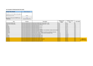
Meter Base and Accessories ListEffective Date: Monday, June 27, 2016Inventory 8111181211813118141181511816135 AMP 1PH UG METER BASE WITH SMALL CLOSING PLATE135 AMP 1PH OH METER BASE WITH 2" HUB200 AMP 1PH UG METER BASE WITH SMALL CLOSING PLATE200 AMP 1PH OH METER BASE WITH 2" HUB200 AMP 1PH UG BASE STUDS ON LOAD & SMALL PLATE200 AMP 1 PH OH BASE WITH STUDS ON LOAD & 2" HUB320AMP 1PH UG METER BASE WITH LARGE CLOSING PLATE320 AMP 1PH OH METER BASE WITH 4" HUB400 AMP 1PH UG BASE BOLT-IN WITH LARGE PLATE400 AMP 1 PH OH METER BASE BOLT-IN WITH 4" HUB200 AMP 3PH OH METER BASE WITH 2.5" HUB200 AMP 3 PH UG BASE WITH SMALL CLOSING PLATE200 AMP 3 PH UG BASE WITH LARGE CLOSING PLATE200 AMP 3 PH OH BASE WITH 3" HUB200AMP 3 PH UG BASE STUDS ON LOAD SIDE SMALL PLATE200 AMP 3 PH OH BASE STUDS ON LOAD & 4" HUB320AMP 3PH UG BASE STUDS ON LOAD/SOURCE LARGE PLAT320AMP 3PH OH BASE STUDS ON SOURCE/LOAD 4" HUB480AMP 3PH UG BASE BOLT-IN WITH 2 LARGE CLOSING PL480 AMP 3 PH OH BASE BOLT-IN WITH 4" HUB480 AMP 3 PH OH BASE BOLT-IN WITH (2) 4" HUBS200 AMP 1 PH 2 POSITION GANG BASE200 AMP 1 PH 3 POSITION GANG BASE200 AMP 1 PH 4 POSITION GANG BASE200 AMP 1 PH 5 POSITION GANG BASE200 AMP 1 PH 6 POSITION GANG BASE350 MCM 2-HOLE CONNECTOR300 MCM 2-HOLE PANELBOARD CONNECTOR500 MCM 2-HOLE CONNECTOR600 MCM 2-HOLE CONNECTOR800 MCM 2-HOLE CONNECTOR250 MCM 3-HOLE CONNECTOR350 MCM 4-HOLE CONNECTORPage 1 of 1All meter bases connected to the Horry Electric Cooperative system must meet certain specifications in order for power to beconnected. This price list is for the established standard meter base and accessories stocked by Horry Electric Cooperative. Aseparate list of manufacturers and models determined to be acceptable is available. Please visit www.horryelectric.com for themost up-to-date price list.Horry Electric Cooperative, P.O. Box 119, Conway, SC 29528
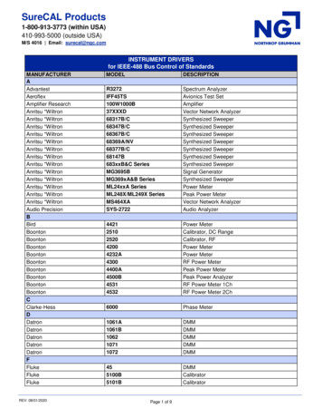
Approved Meter Base List1 Phase Meter Sockets125 amp, with lay-in type lugs200 amp, with lay-in type lugs200 amp, with lay-in type lugs on line side, 3/8” studs on load side400 amp Bolt-in, type K-4, with ½” studs on line and load side320 amp, with lever bypass, 3/8” studs on line and load side1 Phase Gang Sockets2 position, with lay-in type lugs, 200amps/position, 200 amps overall ampacity3 position, with lay-in type lugs, 200 amps/position, 270 amps overall ampacity4 position, with lay-in type lugs, 200 amps/position, 360 amps overall ampacity5 position, with lay-in type lugs, 200 amps/position, 450 amps overall ampacity6 position, with lay-in type lugs, 200 amps/position, 528 amps overall ampacity3 Phase meter sockets200 amp, with lever bypass, lay-in type lugs on line & load side200 amp, with lever bypass, 3/8” studs on line & load side320 amp, with lever bypass, 3/8” studs on line & load side480 amp bolt-in, type K-7T, with ½ ” studs on line and load sideCulter nkU7487-RL-QG-CAPLSiemens/Talon Durham/Square DUAT 111-0JCA UHT-RS101BUAS 917-XJCAUAT777-XGUAS877-PGFT-RS233CUAS 917-OGLE9809-84169810-950747604-82N/AN/AN/AT-H -HSPCulter LSiemens/TalonUA2717-YJCAUA3717-YJCAUA 4719-YJCAUA5719-KJCAUA6719-KJCACulter LU9701-X-QG-HSPU 9761-RRLU n Durham/Square D40407-025T-H 0TCHCH9504K747604-02Durham/Square 7-01FL47407-0249007-02FLUT-H7230ZT-H 7330U9817-9504N/A
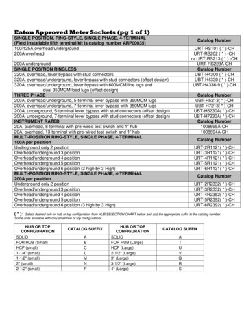
DISCONNECT IS ONTHE WRONG SIDEOF METER BASECORRECTWRONGDISCONNECT INSTALLED ONTHE LOAD SIDE OF METER BASESTUBDOWN IS OUT OFTHE WRONG SIDE OFMETER BASE72" MAXTO48" MIN2 HOLE STRAPSINSTALLEDGROUNDING WIREIN CONDUITLEFT OFFSETRIGHT OFFSETGROUNDING BLOCKPLEASE SEE YOU LOCAL CODE ENFORCEMENT- Only a Horry Electric Meter Base or a meter base from Horry Electric approved List. Horry Electric will Not accept a unibase.- Horry Electric will NOT allow a Main Disconnect or a Generator Bypass Switch/Panel to be mounted on the source side of themeter base. (Mount the main disconnect or Generator Bypass Switch/Panel on the same side as the meter socket.)- If there is a need for 2 Disconnects, Horry Electric will require you to use a 320 Amp Meter Base (see approved list).- All services must have a stub-down conduit. Do NOT use the knockout hole under the meter socket.Stub-down must be at least a 2” conduit (may need a larger stub-down conduit if Horry Electric requires it.)- All stub-downs MUST have at least one Conduit Strap (TWO HOLE) installed prior to scheduling the work to be done.- All services MUST have their own independent ground rod. This ground rod MUST be within 2' of the service.- Grounding conductor MUST come directly out of the meter base straight down to the grounding rod. This groundingconductor MUST be in conduit. (Refer to NEC for size)*Note: This Handout is only intended to Supplement the Horry Electric Specifications Book.REVISEDJAN 2022
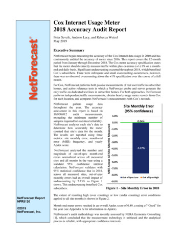
UNIT LETTER OR NUMBER MUSTMATCH UNIT LETER OR NUMBERON FRONT DOOR OF UNITIF THE MIDDLE OF THE TOP METERSOCKET WILL EXCEED 72" MAX HEIGTHFROM THE GROUND, THEN A PERMANENTCONCRETE PLATFORM WILL BE REQUIREDUNDER THE METER PORTION TO MEETTHIS 72" REQUIREMENT.ALL LABELING MUST BE UV RESISTANT,STICK-ON TYPE, NON-TRANSFERRABLEAND AT LEAST 1" HIGH.72"MAXGROUND WIRE(IN CONDUIT)LOCKING TABSINSTALLEDCONDUIT MUSTBE INSTILLED- Only a Horry Electric Meter Base or a meter base from Horry Electric approved List.- The top meter socket will not exceed 72" max height from finished grade. If the heigth will exceed 72" then a permanentconcrete platform will be required to meet the 72" requirement before any meter can be installed.- All removable lids must have locking tabs installed.- All meter sockets must be labeled to match the address on the front door of the unit.- The member will be responsable for supplying the pipe and wire for all services with 7 or more meters.- All stub-downs MUST be installed prior to scheduling the work to be done.- All services MUST have their own independent ground rod. This ground rod MUST be within 2' of the service.- Grounding conductor MUST come directly out of the main disconnect straight down to the grounding rod. This groundingconductor MUST be Copper and in conduit.*Note: This Handout is only intended to Supplement the Horry Electric Meter Specification Book.REVISEDJAN 2022
-Only a Horry Electric Meter Base or a meter base from Horry Electric approved list will be approved. Horry Electric will Notaccept a unibase.-Horry Electric must be contacted in advance to arrange a time to pull meter and/or de-energize service for Generator BypassSwitch to be installed.-The Horry Electric Generator Release of Liability must be signed before meter will be removed or the service is de-energized.-See Meter Base Checklist pages for proper installation instructions.-An electrician must be present to remove the Generlink Bypass Switch for Horry Electric to do anything at the meter basebeyond checking the voltage.REVISEDJanuary 2022
-Only a Horry Electric Meter Base or a meter base from the current Horry Electric approved list will be approved. HorryElectric will Not accept a unibase.-Horry Electric must be contacted in advance to arrange a time to pull meter and/or de-energize service for Generator BypassSwitch to be installed.-The Horry Electric Generator Release of Liability must be signed before meter will be removed or the service is de-energized.-If the meter base has been replaced or if a disconnect has to be relocated to accomodate the installation of the Direct Powerbypass switch, Code Enforcement must inspect the installation before Horry Electric will re-install meter or re-energizeservice.-See Meter Base Checklist pages for proper installation instructions.-An electrician must be present to remove the Generator Bypass Switch for Horry Electric to do anything at the meter basebeyond checking voltage.REVISEDJanuary 2022
-Only a Horry Electric Meter Base or a meter base from Horry Electric approved list will be approved. Horry Electric will Notaccept a unibase.-Horry Electric must be contacted in advance to arrange a time to pull meter and/or de-energize service for Generator BypassSwitch to be installed.-The Horry Electric Generator Release of Liability must be signed before meter will be removed or the service is de-energized.-Code Enforcement must inspect Generator Bypass Switch installation before Horry Electric will re-install meter or re-energizeservice.-See Meter Base Checklist pages for proper installation instructions.REVISEDJanuary 2022
NESC and/or NEC should be consulted for further details. SECTION 3 METERING 3. Available service voltage A. Single phase 2 wire 120 V B. Single phase 3 wire 120/240 V C. Single phase 3 wire 120/208 V Network D. Single phase 3 wire 240/480 V a. All installations will require an instrument rated meter E. Three phase 4 wire 120/240 V Delta F.