Transcription
Abbe 60 RefractometerUser Guide
DECLARATION OF CONFORMITYAccording to ISO/IEC Guide 22 and EN 45014Manufacturer's NameBellingham & Stanley Ltd.Manufacturer's AddressLongfield Road,Tunbridge Wells,Kent TN2 3EYUnited Kingdomdeclares that the productProduct NameAbbe 60 RefractometerModel NumberAllis designed to conform to the following Product Specifications:SafetyBS EN 60950-1:2002EMCEmissionsBS EN 61000-6-3:2007ImmunityBS EN 61000-6-2:2007SupplementaryEmission for residential,commercial and lightindustrial environmentsImmunity for industrialenvironmentsThe product herewith is designed to comply with therequirements of the EMC Directive 89/336/EEC.This symbol is an internationally agreed indicator that the productbearing it should not be disposed of as general waste or garbage whichmight end up in landfill sites, but should instead be sent for specialprocessing and/or recycling in those countries where appropriatelegislation and facilities are in place.This symbol indicates a caution or warning, please refer to the manual.
Abbe 60 User Guide (Eng)B S Code : 10-292Issue 4BJanuary 2008 Copyright Bellingham Stanley Ltd. 2008Every effort has been made to ensure the accuracy of the contents of this manual. However, Bellingham Stanley Ltd. can assume no responsibility for errors contained in the manual or their consequences.Printed in United Kingdom.Bellingham Stanley Ltd.Longfield Road, Tunbridge Wells,Kent, TN2 3EY, United KingdomPhone: 44 (0) 1892 500400Fax: 44 (0) 1892 543115sales@bellinghamandstanley.co.ukBellingham Stanley Inc.1000 Hurricane Shoals Road, Building D,Suite 300, Lawrenceville, GA 30043, USAPhone: 770 822 6898Fax: 770 822 9165sales@bs-rfm-inc.comPage 1
Installing the instrumentCarefully remove all of the packing material. It is recommended that the box and other packingmaterials are retained so that, should the need arise, the refractometer can be safely returned tothe manufacturer. Remove the cable tie that secures the upper prism box during transit. Open theupper prism box and remove packing material from between the two prisms.Contents listB S codeAbbe Refractometercomprising:1Operating Instructions1Instruction manual CD-ROM1Power supply1Bottle of monobromonaphthalene1Calibration test piece1Mains leadCalibration Tablessee below for part number10-29255-30055-10410-43see below for part numbersee below for part numbersee below for part numberPart numbersAbbe refractometer part numbersModel60 / 9560 / DR60 / ED60 / LRPart number10-0310-9910-0410-06Calibration test pieceGlass, 10-44Glass, 10-44Silica, 10-46Silica, 10-46Calibration TablesNot supplied10-29510-297Power lead part numbersDescriptionMains leads (for use with 55-104)UK Version 230V61-191Page 2Euro Version 230V61-193US Version 110V61-192
Positioning the systemPlace the instrument, and separate light source if used, on a flat and stable bench which is: dry and indoorsaway from draughty or hot equipment like fans or heatersout of direct sunlight or strong ambient lightaway from potential sources of interference, such as RFI generating equipmentwithin reach of a power pointnot using a power circuit that also has large motors or noise generating equipmentconnected to itMains connectionThe power supply adapter is supplied with a moulded mains cord and plug, to suit one of severalsocket types. For UK lead, replace fuse only with the type indicated on plug.TypePlug StyleUK (230V)EU (230V)US (110V)13 Amp square pin to BS363/AEuropean Schuko plug253 pin American plugMains cord wire eBlackWhiteEarth(Ground)Green / YellowGreen / YellowGreenPower requirementsVoltageMaximum load110 to 230V 10%, 50 to 60 Hzless than 50 mAPower supply adapterRISK OF ELECTRIC SHOCK: For electrical safety information, read the leaflet enclosed with the power supply. For indoor use only. Must be kept dry. Disconnect the equipment from the mains supply before unplugging the mains leadfrom the power supply unit. Do not open the power supply adapter. No user serviceable parts inside.WARNING: For indoor use only. Must be kept dry. No user serviceable parts inside. Do not open. Do not cover, designed to operate with free air convection. No cleaning required.Page 3
Instrument overviewAbbe 60 refractometers can be used to measure the refractive index of liquid or solid samples for awide range of applications.There are 2 versions of the instrument:Direct Reading models60/95Range 1.300 to 1.53560/DR Range 1.300 to 1.740Sample values can be read directly from the scale graticule in either refractive index or %sucrose( Brix).These models have a built-in adjustable L.E.D. light source at approximately 589nm wavelength.High Accuracy models60/ED Range 1.30 to 1.7460/LRRange 1.20 to 1.70The High Accuracy models have a scale graticule graduated in linear divisions. The sample readingsmust be converted to refractive index (or other scales such as Brix) using either a software programor conversion tables.A separate monochromatic light source is required; e.g. a Spectral Lamp Unit with a cadmium,mercury or sodium bulb.Page 4
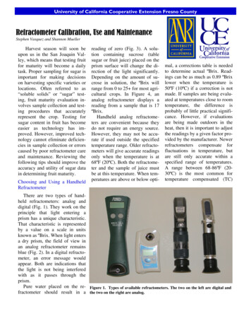
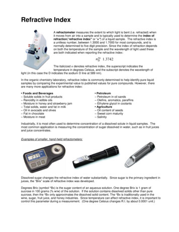
Main parts & controlsDispersion drum(Direct Reading models)Micrometer drumWater nozzleUpper prism shutterUpper prism boxIntegral L.E.D. light source(Direct Reading models only)Lower prism boxWater nozzleToggle clampPower switch(Fitted to earlymodels only)PowerconnectorScale telescopeTemperature displayControl knobCalibrationAdjustmentcoverDesiccatorPage 5
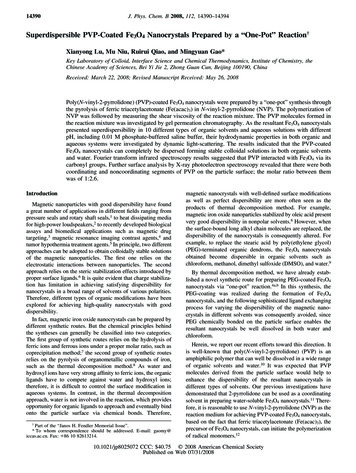
The upper & lower prism boxesA liquid sample to be tested is placed on the measurement prism and the upper prism is clampeddown onto it forming a thin layer of the sample. Light from the light source passes through upperprism, then is refracted through the sample layer and into the measurement prism.The upper prism box is held in place by a toggle clamp, which also forces the box up by a fewmillimetres when opening. The toggle clamp also prevents the upper prism box dropping directlyonto the measurement prism and causing damage to the surface.The upper & lower prism boxes both incorporate water jackets, each with two hose connectionnozzles. This enables the sample to be temperature controlled from a water circulator.Prism box toggle clampMeasurement prismLower prism boxWater nozzlesAny deterioration of the surface condition of the measurement prism will limit the performance ofthe instrument and make accurate measurements difficult.It is important to keep the measurement prism in good condition.The temperature display moduleThe current temperature of the measurement prism is continually monitored and shown on thedisplay on the rear face of the instrument in degrees Celsius.Page 6
Direct Reading instruments onlyThe Direct Reading instruments have an integral L.E.D. (light emitting diode) light source for sampleillumination.L.E.D. light sourceL.E.D. arm adjustmentsA dispersion drum is fitted to Direct Reading instruments to enable colours other than yelloworiginating from the L.E.D (or more significantly, an alternative white light source) to be removedfrom the field view. This will sharpen the borderline and allow accurate setting against thecrosswires.High Accuracy instruments onlyHigh Accuracy models are not fitted with an integral L.E.D. light source because a monochromaticlight source, such as a sodium lamp, is required to achieve the measurement precision.A window and shutter are fitted in the lower prism box, which allows the instrument to bealternatively used in reflection, rather than transmission, mode. This is useful when reading darksamples. (See page 3-4 for more details)Lower prism box windowLower prism box window shutter Turn the knob anticlockwise to close the shutter for transmission measurementsTurn the knob clockwise to open the shutter for reflection measurementsPage 7
Initial setting upPower supplyAll Abbe 60 refractometers are supplied with an external power supply, which should be pluggedinto the sealed power connector on the side of the instrument.The power supply itself is connected to the mains supply by a moulded mains lead, which is alsosupplied with the instrument.Connect the mains lead to the mains supply and switch on the supply.Early models only, with serial numbers prior to A01051Switch the instrument on by pressing down the power switch, located next to the instrumentpower connector.Altering the focus of the telescopesTo alter the focus of either of the telescopes, move the lens cap away and towards the main bodyof the instrument until the scale and the crosswires are well defined. To help the lens cap move,twist it whilst adjusting the focus.Below are examples of the views that you will get when looking down each of the telescopes (thescale view is that of a Direct Reading instrument).Scale viewField viewAdjusting the upper prism box shutterThe upper prism box shutter has two separate functions.The first is to control the amount of light from the light source that is passed through the sample;this is necessary to adjust the contrast between the light and dark parts of the borderline.The other use is to limit unwanted, ambient light entering the prism. If you are using the integralL.E.D. light source on a Direct Reading instrument, it is recommended that the shutter shouldinitially be open about 2mm. This will restrict the amount of white light entering the sample. Whenusing a spectral light source the shutter has a lesser effect, as the light source will be able to floodthe sample with light.Page 8
Measuring a sampleSetting the borderlinePush the toggle down and raise the upper prism box. Clean the polished surfaces of the upper andmeasurement prisms using distilled water with a soft tissue. Finish off by drying the prisms with softtissues.Apply a few drops of sample to the centre of the measurement prism with a pipette. Lower theupper prism box and lift the toggle clamp to lock it onto the measurement prism. Any excesssample should be wiped away using soft tissues; this will improve the definition of the borderline.Look into the field telescope and rotate the control knob until the borderline (thepoint where the light and dark areas meet) comes into view.It should then be aligned with the centre of the cross hairs inthe field telescope.To obtain the optimal borderline quality, both the light source position and theprism box shutter should be adjusted.Direct Reading models (Abbe 60/95, 60/DR)The L.E.D. light source has two adjustable joints, allowing the light to be easily positioned toprovide the best borderline. To adjust a joint, turn the associated clamping knob anti-clockwiseuntil it is loose enough to allow the joint to move. Make the adjustment and tighten the knob byturning it clockwise, whilst holding any adjustments in place.The L.E.D. should be positioned so that it illuminates just the bottom of the upper prism.The dispersion drum control knob should be adjusted to remove as much colour as possible fromentering the field view. This will improve the borderline quality. The borderline might need to bere-aligned with the crosshairs after setting the dispersion drum.High Accuracy models (Abbe 60/ED, 60/LR)Close the lower prism box window shutter by turning the knob anticlockwise.Position the external light source directly in front of the Abbe and align the opening in the lightsource with the upper prism box. Next, adjust the height of the light source, so that all the upperprism box is well illuminated with the light.If the light source being used requires a filter, this should be slipped over the field telescope lenscap.Page 9
Determining the reading valueDirect Reading models (60/95, 60/DR)Look through the scale telescope and read the measurement value directly from the scale in eitherrefractive index or %sucrose ( Brix).High Accuracy models (60/ED, 60/LR)Turn the micrometer drum to the 0 position. Then whilst looking at the scale through the scaletelescope, turn the micrometer drum until the previous scale division is straddled centrally by thetwo fiducial lines.The example shown would give a value through the scale telescopeof 33.3.Next, read the value on the micrometer drum, this example being 4.3.The total scale reading will then be:The value through the scale telescope the micrometer value divided by 100Example: 33.3 4.3 / 100 33.3 0.043 33.343Scale reading 33.343The operator can then determine the refractive index from the scale reading by one of twomethods: The Abbe Utilities softwareCalibration tablePage 10
Using the Abbe Utilities softwareEvery Abbe refractometer is supplied with an Instruction Manual CD (55-300), contained within thisCD is a copy of the Abbe Utilities program, which runs on Microsoft Windows. It provides theability to convert from Abbe scale reading to refractive index and other scales.Firstly, check that the Abbe Setup datamatches that of your instrument and lightsource. If the settings are not correct, pressand edit the values.To convert an Abbe scale reading intorefractive index, place the cursor in the dataentry box below ‘Abbe’, type the Abbescale value ‘17.243’ and press enter. Theequivalent RI, Brix and selected UDS scalevalues will be shown in the relevant boxes.R.I. readingAbbe scale readingUsing a Calibration TableEvery High Accuracy instrument is supplied with a calibration table booklet for sodium D line,which will convert Abbe scale readings into refractive index. Below is an example for how therefractive index value for an Abbe scale reading of 17.243 is calculated, using calibration 46696.72473374317.31.46789.816826835First find the correct row in the table,which for the example would be 17.2.Now find the correct column in thatrow, e.g. 0.04. The column and rowposition would give the correct Abbescale reading for 17.24.To calculate the refractive index reading, take the RI value for 17.20, which is 1.46696 andsubstitute the last 3 numbers for the 3 numbers found at 17.24 in the table, 733. This would makethe reading 1.46733.Finally, use the third decimal place of the Abbe scale reading.Find the refractive index reading for the next column, in this case, 17.25, which would be 1.46743.Then calculate the RI from:Where: H C A * D C 10 1.46743 1.46733 A * 3 1.4673310 A 1.46736H Next columns RI value 1.46743C First columns RI value 1.46733D Scale reading 3rd DP 3A Actual RICleaning the prismsPage 11
With the measurement taken, the prism can now be cleaned. Samples should be removed from theprism surfaces as soon as practical after measurement. Leaving sample between the prisms for longperiods, and allowing it to dry, can cause the two prisms to stick together.The sample should be removed from both prisms using a suitable solvent; distilled water or alcohol,depending upon whether the sample is water or oil based, and cleaning with tissue. The prismsshould then be finally washed with distilled water or alcohol and dried with clean tissue.Note:When cleaning the prisms, please remember that excessive rubbing with abrasive tissues couldscratch the prism surfaces. This would reduce the quality of the borderline and also cause samplecontamination. B&S do not recommend the use of aggressive solvents such as acetone – always usealcohols or other non-aggressive solvents.Reflection mode (High Accuracy models only)If the sample layer is optically dense at the wavelength used, then insufficient light may not passthrough it to provide a visible borderline. This problem can generally be overcome by using internalreflection of the light at the interface of the prism and sample.To use internal reflection Slide down the “Upper prism shutter” to prevent light entering into the upper prism. Open the “Lower prism box window shutter” by turning the knob clockwise as seen fromthe front of the instrument. Adjust the light source to enter the “Lower prism box window.The borderline as seen in the field telescope will however be inverted, the darker part of the fieldbeing at the top. Usually the contrast is not so good as with transmission mode but in general asharp line can be obtained.Page 12
Calibrating the instrumentThe calibration of all Abbe 60 refractometers can be adjusted to accurately set the scale relative toa test piece with known refractive index. This adjustment should only need to be made atinfrequent intervals, but it is recommended that the test piece be applied as a daily routine to checkthat all is in order and the instrument is reading correctly. Certainly check at each change of usersince the setting position varies from one person to another.Checking the instrument with the test pieceApply two small drops of monobromonaphthalene contact liquid (suppliedwith the instrument, code no. 10-43) to the centre of the measurementprism, using a small wooden or plastic stick. The test piece should beplaced polished side down onto the prism on top of the contact liquid.Take care when applying the test piece not to scratch the prism. Thecontact liquid should spread out under the test piece and cover the wholeof the interface between the test piece and the prism.It is important to use the correct amount of contact liquid; there should be just sufficient to coverthe interface but should not spread beyond the test pieces edges. The correct amount can only befound with experience.To check the test piece is applied correctly, see that it does not rock. If it does, remove the testpiece and clean off the contact liquid; then re-apply as above.To remove a test piece from the prism, apply an alcohol-based solvent liberally around the testpiece and allow it to “float” off of the prism surface with the minimum of sliding.Each test piece is identified by a serial number and is supplied with a Certificate of Precisionspecifying its actual refractive index.For Direct Reading models, the refractive index can be read from the scale and compared with thetest piece value.For High Accuracy instruments, the correct Abbe scale reading for the silica test piece can be foundon the front page of the Calibration Table supplied with the instrument. If the Abbe Utilitysoftware is used, pressand the correct Abbe scale reading will be displayed.Page 13
Adjusting the instrument calibrationEnsure that the borderline is accurately aligned with the cross wires in the field telescope. Unscrewand remove the Calibration Adjustment Cover.Direct Reading models (Abbe 60/95, 60/DR)Gently adjust the calibration screw using a large flat screw driver so that the correct reading isshown in the scale telescope.High Accuracy models (Abbe 60/ED, 60/LR)Set the micrometer drum to the last 2 decimal places of the scale reading for the test piece, whendisplayed to 3 decimal places. For example, if the scale reading should read 16.275 then themicrometer drum should be set to 7.5. If the scale reading should be 16.002 then the micrometerdrum should be set to 0.2.Gently adjust the calibration screw using a large flat screw driver so that the correct value is in themiddle of the two fiducial lines. If the scale reading should be 16.275, then the scale should read16.2, e.g. the scale marker for 16.2 should be straddled by the fiducial lines.All modelsFinally, always replace the Calibration Adjustment CoverPage 14
Temperature effects on the measurementTemperature correction of the refractometerIf the instrument is used to take measurements at any temperature other than 20 C, then it will benecessary to apply a temperature correction to the scale reading. This is to compensate for thechange of refractive index of the prism at the working temperature; the instrument being initiallycalibrated at 20 C.Direct Reading modelsAbbe 60/95Measured Brix valueCorrection: Brix/ C01020304050607080900.005 0.005 0.005 0.004 0.004 0.004 0.003 0.003 0.003 0.003Measured Refractive index1.30 to 1.5350.0000076Correction: Refractive Index/ CAbbe 60/DRMeasured Brix valueCorrection: Brix/ C010203040507080900.005 0.005 0.005 0.004 0.004 0.004 0.003 0.003 0.003 0.003Measured Refractive index1.30 to 1.74Correction: Refractive Index/ C0.0000078Examples:60A 60/95 gives a reading of 35.4 Brix at a temperature of 75 C(T – 20) x 0.004 55 x 0.004 0.22Scale reading of instrument 35.4Corrected reading 35.62A 60/DR gives a reading of 1.4864 at a temperature of 70 C(T – 20) x 0.0000078 50 x 0.0000078 0.00039Scale reading of instrument 1.4864Corrected reading 1.48679High Accuracy models (Abbe 60/ED, 60/LR)Using the Abbe Utilities softwareEnter the measurement temperature in Abbe Setup and the correction will be carried outautomatically.Using a Calibration TableDetails for correction with temperature are shown at the end of the tables.Page 15
Temperature correction of the sampleThe refractive index of all samples will vary with temperature. If it is required to know therefractive index of the sample at 20 C, then either the instrument must be controlled at 20 C, asdescribed below, or a correction value for the sample must be added to the scale reading.The correction value will vary considerably with the type of sample. Glass samples have a lowtemperature coefficient, water based products are higher and oils and chemicals generally greatest.Typical (and very approximate) values are:SampleTemperature coefficient: Change in index / CelsiusGlass 0.00001Water-0.00010 (-0.07 Brix)50% sucrose sample (50 Brix)-0.00017 (-0.08 Brix)Edible oil-0.00040Correction values for sucrose solutions measured on the Brix (% Sucrose) scale are shown in thetable below. The correction values should be added to the scale reading.Page 16
Temperature CelsiusScale reading 51Example:A 60/95 gives a reading of 35.4 Brix at a temperature of 32 CScale reading of instrument 35.4Correction 0.99Equivalent value at 20 C 36.39Page 17
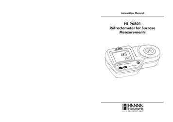
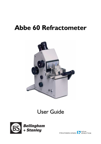
Temperature control from a circulatorBoth the fixed and hinged prism boxes are fitted with nozzles for water circulation in order tomaintain the prisms and sample at known temperatures.By controlling the instrument to a constant temperature, the time necessary for the instrument tostabilise after applying a sample to the prism will be minimised and measurement conditions will beoptimised for high accuracy work.If it is practical to control the instrument temperature to 20ºC, the corrections for the instrumentand the sample detailed above will not be required.It is recommended that the two boxes are connected in series as follows.Incoming water should be fed into the lefthand side of the main body, when viewedfrom behind. The water will exit throughthe right side of the main body. A 45cmlong pipe should be connected to thisnozzle and connected to the right handnozzle of the upper prism box. A pipe onthe left nozzle on the upper prism box willreturn the water back to the circulator.With the instrument set-up as above, theAbbe will have both the water connectionsto the water bath on the left hand side,when viewed from behind. It is advisableto secure the pipes to the nozzles withhose clips. (The photograph shows the pipes without clips for clarity).Page 18
Measurement techniquesSample applicationLiquid samplesIt is recommended that liquid samples be transferred to the prism surface using a pipette ratherthan a stirring rod or pouring directly from a beaker. After taking up the sample, any drips adheringto the outside of the pipette should be wiped off then discharge a few drops from the pipettedirectly onto the prism surface and close the prism box. This is of considerable importance whentaking concentration measurements since thin films adhering to a stirring rod and exposed to theatmosphere can evaporate solvent rapidly when moved through the air, giving rise to errors inmeasurement.Solid SamplesThese are applied in the same manner as the test piece using a contact liquid. A surface must beprepared, polished as flat as possible and placed on the prism surface with the hinged prism openedout of the way. If the solid has an index higher than 1.65, methylene iodide can be used as a contactliquid (B&S code 10-61) in place of monobromonaphthalene which can only be used up to this limit.Thin FilmsResults may be obtained on most thin films but here a technique must be evolved, determined bythe material and conditions.Direct Application (Reflection mode: High Accuracy models only)Soft plastics and rubbery materials may be cured in a press between thin sheets of aluminium foiland reduced to a thickness of about 0.25mm. After preparation ensure that the prism surface isclean, strip off the foil on one side of the film and apply the exposed surface directly to the prismusing no contact liquid.Indirect Application (Reflection mode: High Accuracy models only)Resins and other low melting point solids are best prepared by melting them onto a thin glasssubstrate (B&S code 10-59). After hardening, the substrate should be placed on the prism surfacewith a contact liquid with the coated surface uppermost. Two borderlines will appear, one due tothe sample, the other due to the substrate which may be previously found and ignored. It isessential that the refractive index of the substrate should be greater than that of the sample.Dark samples (Reflection mode: High Accuracy models only)With certain materials of a non-transparent nature, such as thick oils, tar, marzipan etc., too muchlight may be absorbed in the sample film or be so scattered that definition is lost. In these cases, thetrouble can generally be overcome by using reflection mode.Page 19
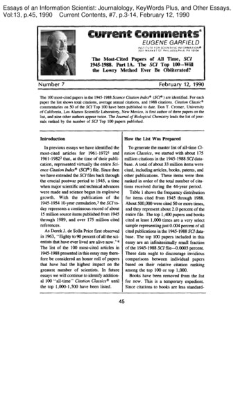
AccessoriesVolatile Liquid CellThis comprises a rectangular glass block, with oneside hollowed out to form a cavity. Two holes passbetween the cavity and the opposite face of theblock.To use the cell, first ensure that the prism surfaceand the cavity face of the block are clean.Place the block, cavity down on the prism surface,and by means of a syringe, introduce sample into thecavity via the end filling port, leaving the central portclear for the escape of air. Fill the cavity and thefilling ports to the top face of the block. Afterremoving the syringe, close the filling ports by layingthe thin plate over the top surface. The sample isnow completely isolated from the atmosphere and will not be subject to evaporation.The cell capacity is in the region of 0.3 ml and this may be saved after measurement by drawingback into the syringe or lost by lifting the cell from the prism face for cleaning and drying.Divided Cell for differential measurementsThis is a circular cell with a dividing partitionproviding two sample compartments of semicircularform.Before use, it is necessary to clean the prism surfaceand the base disc of the cell. Place a small drop ofcontact liquid in the centre of the prism surface, thenplace the cell in position on top of the prism with thepartition parallel to the sides of the prism andcentral.Sample and reference are placed in the separatecompartments and the control knob turned to bringthe borderlines into view. The borderline due toeach half of the cell occupies about two thirds of thefield, thus extending sufficiently across the cross line for a setting to be made. The two may becompared accurately one against the other and, since they are in the same cell, under identicalconditions, there is little risk of error due to temperature. It should be noted that, when observedin the field of view, the borderline to the left side arises from the sample on the right side of thepartition and vice versa. This is due to the optical system within the instrument causing a reversal.Page 20
Funnel FlowcellAttaching the flowcell to the prism box. Remove the two hexagon headed bolts securingthe prism box hinge to the lower prism box andcompletely remove the upper prism box. Remove the two countersunk screws from eitherside of the toggle fastener and detach fastener. Fit two angle brackets provided with the flow-cellto either side of the prism plate using
Product Name Abbe 60 Refractometer Model Number All is designed to conform to the following Product Specifications: Safety BS EN 60950-1:2002 EMC Emissions BS EN 61000-6-3:2007 Emission for residential, commercial and light-industrial environments Immunity BS EN 61000-6-2:2007 Immunity for industrial environments