Transcription
OPEN ACCESS GUIDE TO AUDIOLOGY AND HEARINGAIDS FOR OTOLARYNGOLOGISTSFITTING HEARING AIDS: TECHNICAL ASPECTSFaheema Mahomed Asmail, Anel Le Roux, De Wet SwanepoelThis is the 1st of two chapters on hearingaids. This chapter discusses the technicalaspects; the 2nd chapter deals with practical aspects of fitting hearing aids.Major technological advances in hearingaids and development of hearing instrument technology have led us into themodern era of integrated and digital hearingaids.ANALOGUE TECHNOLOGYLinear amplification Conventional, more basic technology All sound (speech frequencies) receivesame amount of amplificationNon-linear amplification Makes soft sounds louder But does not amplify loud incoming soundsAdvantage: Less costly technologyDIGITALLY PROGRAMMABLE TECHNOLOGYResearch on digital hearing aids had startedby the 1960s. In 1996 the first fully digitalhearing aids became commercially available, with a variety of hearing aids in termsof size, placement, amplification, technology and cost. Today most hearing aids manufactured are digital.The integrated circuit and digital phase alsosaw the manufacturing of open canal hearing aids, which led to the introduction ofreceiver-in-the-canal/ear (RIC/RITE) hearing aids. Nowadays technologies such asBluetooth and wireless signal transmissionare incorporated into hearing aid technology, providing more connectivity and communication options for people with hearingloss.Hearing Aid Circuitry and TechnologyTypes of amplification used in hearing instruments are divided into 3 categories(Table 1):1. Analogue technology (linear vs. nonlinear amplification)2. Digitally programmable3. Digital technology More sophisticated technologyHearing aids connected to computer so that1-4 programs programmed/selected fordifferent listening situations Some have only one program that adaptsautomatically to different situations e.g. byPeak Clipping Often 1 microphone to ensure betterspeech intelligibility in noisy situationsAdvantages Can adapt to auditory surroundings Speech better understood in noisybackgroundDIGITAL TECHNOLOGY Most advanced technologyMicrochip in hearing aid does millions ofcalculations/second From these calculations, it determines howmuch amplification is needed to ensure acomfortable, audible sound Background noise automatically lessamplified Technology available in 1 program whichadjusts automatically, or in 4 programscontrolled by user Omni-/directional microphones availableAdvantages Very natural sound quality Optimal amplification of speech ensuresbetter speech intelligibility in backgroundnoise Less chance of acoustic feedbackTable 1: Three different hearing aid circuitsand technologies
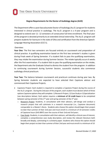
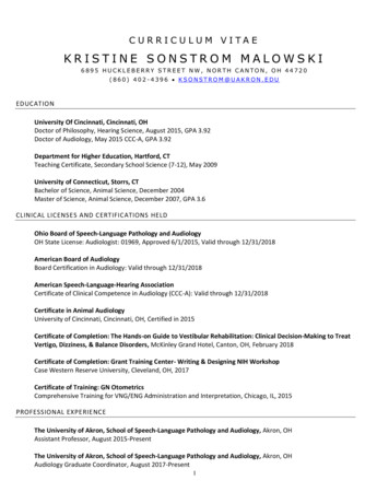
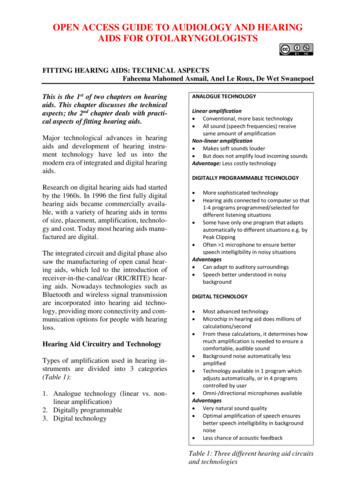
1. Analogue technologyThe World Health Organisation (WHO) hasguidelines for the preferred profile forhearing aid technology suitable for low andmiddle-income countries (WHO, 2017).Even though digitally programmable anddigital technologies are currently mostlyused in hearing aid technology, it is essential to have knowledge of the more basicanalogue technology. Not only does it helpthe clinician to understand where moreadvanced technologies originated from, butknowledge of these technologies also assists the clinician to provide support topatients still using older technology. Manydeveloping countries still use older technology as access to computers is limited.The word “analogue” means “similar” or“equivalent”. Analogue hearing aids convert sound waves into electrical waves. Theincoming acoustic signal or sound wave isconverted into electric current by a microphone. The current is then modified in theamplifier and reconverted by the receiverinto sound (Figure 1).Figure 1: Analogue technologyWhen a sound signal is transformed from anairborne signal to an electrical analoguesignal, the characteristics of the signalremain unchanged. These electrical wavescan be modified in a number of ways toaccommodate specific hearing losses; this isachieved with filters/trimmers.Two types of analogue circuitry exist: Linear amplification Non-linear amplificationLinear amplification: Linear amplificationoccurs when the same preset amount ofamplification is added to all incoming signals (1:1), regardless of the loudness levelof the incoming sound. The amount of amplification is calculated to amplify the incoming signals to such a level that thehearing aid user can hear speech clearly inthe ideal listening environment (with no orlittle background noise). The disadvantageof this kind of amplification is that the softerincoming sounds usually are not amplifiedenough, while louder incoming sounds areoften amplified too much. Peak clippingoften has to take place to compensate forthese loud sounds, which results in distortion of the final (amplified) outgoing signal.Non-linear amplification: The amplifiedsound with non-linear technology is usually a more pleasing sound than the soundproduced by linear amplification. With nonlinear amplification, a fixed knee-pointattempts to make soft sounds louder, but notto amplify loud incoming sounds i.e. softerincoming sounds are amplified more whilelouder sounds are less amplified. Theamount of amplification is adapted according to the intensity of the incoming sound.Up to the kneepoint, the same preset amountof amplification is added to the incomingsignal, but once the kneepoint is reached theamount of amplification added to theincoming signal is modified (Figure 2).Non-linear amplification aims to compensate for factors such as loudness recruitment in hearing-impaired people and is alsosafe in terms of possible over-amplification,because the loud incoming sounds do notreceive too much amplification. The distortion resulting from peak clipping is also lesswith linear amplification than non-linearamplification.2
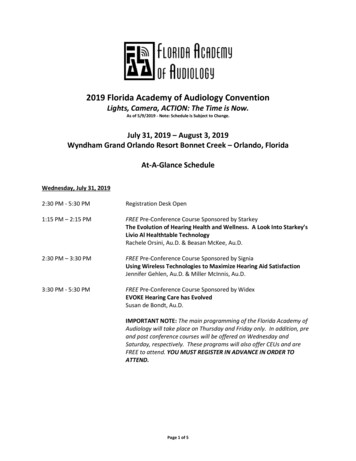
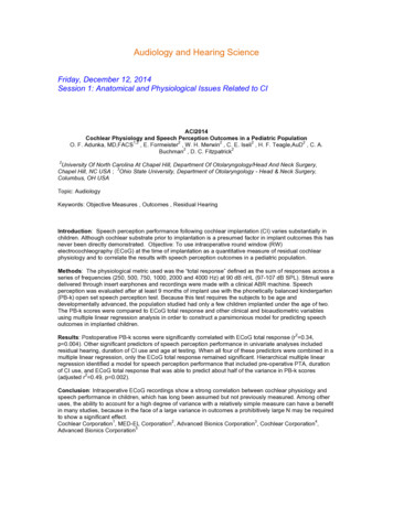
Figure 2: Kneepoint adjustment to hearingaid2. Digitally programmableThese are analogue hearing aids that arefitted and finetuned with the assistance of acomputer. The processing of the hearingaid, however, is still analogue – the word“digital” refers mainly to the computer towhich the hearing aid is connected duringthe fitting and finetuning process. In otherwords, the digital component is purely forprogramming and reprogramming the parameters of the hearing aid, as illustrated inFigure 3.Figure 3: Digitally programmableInstead of setting trimmers, the frequencyresponse, gain, maximum output and compression parameters of digitally programmable hearing aids are set by attaching thehearing aid to a computer with a cable, orwirelessly. The hearing aid contains a memory chip with selected settings. This component does not perform any signal processing, but only adjusts and stores the controlsettings.This type of setting process allows increased flexibility and ease of fitting the hearingaid, but does not necessarily result in improved sound quality. Because the settingsof digitally programmable hearing instruments can be manipulated using a cableconnection to a computer or a special programming device, several of the hearing aidparameters can be changed and comparedsimultaneously by the mere press of abutton. The possibility of switching instantaneously from one setting to anotherallows the wearer to judge which setting isthe most suitable for a specific situation e.g.understanding speech in noise. The varioussettings can also be stored digitally in thehearing instrument or in a remote controlunit and later selected by the user to suit thelistening situation.Digitally programmable hearing aids thusprovide more sophisticated technology,different programs for different listeningconditions, and more audible speech perception in the presence of backgroundnoise.3. Digital technologyDigital hearing aids convert sound waves toa digital (numerical) signal, like what computers use. Because of the precision ofdigital signals, the sound can be duplicatedwith much more accuracy. A microchip(microprocessor) processes this information using exact mathematical calculations,resulting in much more flexibility in fittingand fine-tuning. The components of a fullydigital hearing aid are illustrated in Figure4.The 1st and last stages depicted in Figure 4are common to all types of hearing aids.However, the intermediate stages are unique to digital systems. These are the Analogue-to-Digital Converter (ADC), themicroprocessor and the Digital-to-Analogue Converter (DAC). With digital hearing3
aids, the acoustic signal therefore must firstbe converted into a form that can be manipulated by the computer to be proces-sedand finally reconverted back to an acousticsignal. provide a better sound quality than anyother type of technologyDigital hearing aids can be customisedto suit different hearing loss requirements and specific personal needsDigital technology allows production ofsmaller hearing aids than previouslypossible with analogue technologyBasic components of a hearing aidFigure 4: Digital technologyThe specific stages followed by digitalhearing aids are: Incoming sound wave (acoustic signal)converted by microphone into electrical (analogue) signal Analogue-to-Digital Converter (ADC)creates digital representation of original electrical (analogue) signal, in orderto generate a configuration that can beoperated by the microprocessor Microprocessor processes the signal,using various algorithms, e.g. filtering,noise reduction or speech enhancement(digital signal processing) Digital-to-Analogue Converter (DAC)creates electrical (analogue) signal fromdigital output of microprocessor Amplifier amplifies thesignal, which isthen reconverted into a sound wave bythe receiver and delivered to the humanearHearing aids contain a large number of electronic components and controls. The maincomponents are (Figure 5): Input transducer (microphone, telecoil,direct audio input)AmplifierReceiver (loudspeaker)BatteryBenefits of digital processing Because digital processing allows formore complex and detailed operations,the same hearing aid can be fitted formany different hearing loss configurationsBy translating sound into numericalvalues and by doing complex mathematical calculations, digital hearing aidsFigure 5: Custom-made and Behind-theEar (BTE) hearing aids4
How does a hearing aid work? (Figures 5,6)142, 35The amplifier (2) makes the sound louderand sends the amplified sound to thereceiver. The receiver (3) sends the amplified sound into the ear canal. The volumecontrol (4) adjusts loudness. The battery (5)supplies the powerInput transducer (Figure 6)The purpose of the input transducer is toreceive information from the environmentand to produce a good frequency responseand low distortion. The input transducer canbe a1. Microphone2. Telecoil3. Direct audio input (DAI): only available in Behind-the-ear aids (BTE’s)1. Microphone2, 3145Figure 6: Workings of Behind-the-ear(BTE) and Custom-made hearing aids; Themicrophone or input transducer (1) picksup the sound and sends it to the amplifier.The microphone converts the incomingsound wave energy into electrical energy.Since the frequency and intensity pattern ofthe sound waves represent coded information concerning the message, they must beduplicated as exactly as possible.Omnidirectional microphone: Most microphones used in hearing aids are omnidirectional, and are equally sensitive to acousticenergy from 0o to 360o around the listener.They can provide low frequency amplification. However, they provide a reducedsignal-to-noise ratio and are not very functional in listening conditions where directionality or localisation is required. Omnidirectional microphones are ideal for severeto profound hearing losses.Directional microphone (Figure 7): Toimprove speech discrimination in noise, adirectional microphone can be used in BTEhearing aids, where acoustic signals coming from behind the head (180o) aresuppressed (up to 20dB at certain frequencies).5
directional microphone and the directionalmicrophone, depending on the listeningenvironment. The directional microphonecomponent can also adapt its directionalitytowards the primary sound signal (speech)in noisy environments, as it follows thedirection of the primary sound source.Figure 7: Multi-microphoneThis improves a listener’s ability to attendto the frontal sound source. Directionalmicrophones provide improved signal-tonoise ratio as well as directionality andlocalisation in noisy listening situations.However, they often have reduced sensitivity at low frequencies when compared toomnidirectional microphones. Directionalmicrophones are ideal for mild to severehearing losses.Different types of microphones are available (e.g. magnetic and ceramic types), butthe electret condenser microphone is theone most commonly used. This microphone is more durable than the other types,and is less sensitive to hard impact, humidity and changes in temperature. The electret condenser microphone has a built-inlow-noise preamplifier, a smooth frequency response and a low sensitivity to mechanical vibrations. This reduces acousticfeedback.2. TelecoilMulti-microphone system: Most hearing aidmicrophones pick up sounds equally fromthe front, sides and back. Multi-microphonesystems are different. These systems contain both omni- and directional microphones, making switching between the twodifferent microphones, as required by listening situations, possible. In situationswhere competing sounds are a problem, thedirectional mode of this microphone systemallows full amplification of sound from thefront, while providing less amplification ofsounds from the sides and back. In environments where listening to sounds from alldirections is required, the omnidirectionalmode is more sensitive to sounds all around.Multi-microphone systems can be used withBTE’s as well as with certain custom-madehearing aids.Adaptive microphone systems: These areavailable in digital hearing aids. They provide the same functionality as multimicrophone systems, but are completelyadaptive. These microphone systems willswitch automatically between the omni-This is a simple coil on a soft iron core, andwas originally introduced to hearing aids asa telephone aid and can be activated insteadof the microphone with the M-T-O (Microphone-Telecoil-Off) switch or a dedicatedprogramme on the device. The telecoilpicks up a magnetic field (from a telephoneor induction loop system in a room) andconverts it by means of induction intoelectrical energy to be amplified by thehearing aid amplifier.3. Direct Audio Input (DAI) (Figure 8)An audio input system using an electricalinput connection (FM-radio or infraredtransmissions) directly on the hearing aid, isoften used in educational situations. Aninput signal is received from an audio shoewhich snaps over the bottom part of thehearing aid (Figure 8). The input signal isprovided via a 2-pin/3-pin cord, whichplugs into the bot-tom of the audio shoe. Inthis way, a good sound quality can beobtained and interference from background6
noise is limited, especially when there is arelatively large distance to the soundsource.Figure 9: BatteriesZinc air batteries are the most commonlyused disposable type because of long lifespan, high energy density and low environmental impact of used batteries.Figure 8: Direct Audio Input (DAI)Amplifier (Figure 6)The weak signal generated by the microphone or telecoil is fed to the amplifier,which amplifies the intensity of the original low-energy signal into a powerful electrical signal (increases the voltage amplitude).Receiver (Figure 6)The function of the receiver is exactlyopposite to that of the microphone. Whereas the microphone converts acoustic energy to electrical energy, the receiver transduces the amplified electrical impulses orsignals back into acoustic energy / soundwaves.Battery (Figures 6, 9)The battery provides the energy for thehearing aid and makes amplification of theacoustic signal possible. Different sizes (10,13, 312, 675) and types of batteries areavailable. The output produced by theamplifier of a hearing aid determines thebattery drain. Although battery drain cannotalways be exactly specified, hearing aidmanufacturers always specify in the products’ specification sheets what batterydrain can be expected from a hearing aid.Mercury or silver oxide batteries are stillused in some countries for extremely powerful or heavyduty hearing aids, althoughmodern highpower zinc air batteries canalso supply sufficient power for these hearing aids.Alkaline batteries are used with body-worninstruments and hearing aid remote controlsRechargeable batteries are also used inhearing instrument technology for reasonsof cost and convenience. Various rechargeable units are commercially available. These include nickel-cadmium (NiCd) ZincIon, and nickel-metal hydride (NiMH), batteries. NiMH is more environmentallyfriendly and does not build up a memoryeffect which could potentially decrease thedaily longevity of the battery. Most rechargeable systems nowadays have built-inpower supply units through which the entirehearing aid unit is charged, although somebatteries are charged separately.Electroacoustic characteristics of hearing aidsEach individual hearing aid has a specificset of characteristics which makes an instrument suited to a patient's specific audio-7
gram and personal needs. The most impor-tant of these physical characteristics are: Output Gain Frequency responseOutputOutput is often referred to as the maximumpower output (MPO) on hearing aid specification sheets. The MPO is also known asthe SSPL (Saturation Sound PressureLevel). Output is expressed as a number thatis within the applicable measurement standard e.g. ANSI or IEC Standards. The output of a hearing aid can be thought of as theceiling up to which the hearing aid providesamplification. Amplification beyond thispoint is not possible due to output limitingsystems such as peak clipping (older hearing aid technology) or compression (newertechnology) coming into effect when thegain of the hearing aid reaches this point.Selecting appropriate output is a requirement for a proper fit. The output of a hearing aid should not exceed a patient’s Loudness Discomfort Level (LDL) or Uncomfortable Loudness Level (UCL). Therefore,the MPO of a hearing aid is usually basedon this score.GainThe number of dBs by which the outputlevel of a device exceeds the input level isknown as the gain that the hearing instrument provides (“dynamic range” of thehearing aid). The person fitting the hearingaid should select the appropriate gain byselecting the appropriate prescriptive fittingstrategy. Typically, the goal is to provideenough gain to make normal conversationalspeech easy and comfortable to hear. Selecting the correct amount of gain for a hearingloss is not as straightforward as output.Any gain calculating approach or prescriptive fitting strategy may be used, but alwaysremember that the gain number represents2cc coupler measurements and not insertiongain. A 2cc coupler refers to a soundchamber and serves as a substitute for theear canal, providing a standard-sized cavityinto which the amplification produced bythe hearing aid is directed, and is a mechanical way to attach a microphone tothe hearing aid. The coupler measures theinter-comparison of the hearing aids.Frequency responseFrequency response is the output or gaincurve produced by the acoustical 2cc coupler when the input signal is a sinus sweepwith constant amplitude. It presents gain interms of frequency in a curve form. In otherwords, this curve reflects the hearing aid’samplification abilities at different frequencies. This can be adjusted by the hearing aidfitter to set the hearing aid’s gain at specificfrequencies to match the patient’s audiogram and needs.Sound Delivery SystemsA sound delivery system couples the hearing aid to the patient’s ear, and delivers thesound to the ear. The three types of sounddelivery systems are:1. Earmould2. Slimtube and dome/slimtip3. Shell1. EarmouldAn earmould is an individually fabricatedear insert that is coupled with the Behind theEar component (BTE), and channels thesound produced by the BTE, via the earcanal to the eardrum. Several earmouldtypes/styles are available to which manydifferent modifications are possible to make8
the earmould best suited to a specific patientor a specific type of hearing loss.For an earmould to be optimal it must Keep the hearing aid in the ear Retain the BTE component on the outerear Provide a good acoustic seal to preventacoustic feedback Appropriately modify gain, frequencyresponse and output of the hearing aid Be comfortable to wear for extendedperiods of time Be cosmetically acceptableEarmould style: The style/type of earmouldis determined by the audiogram, especiallythe low frequency thresholds (1251000Hz). The more severe the hearing lossis in the low frequencies, the less open theearmould should be. For 60dB HL in thelow frequencies, a skeleton mould (Figure10) can be considered. Skeleton moulds areusually more comfortable and cosmeticallymore appealing. Hearing losses 60dB HLin the low frequencies require a full conchamould to better seal the ear and to preventfeedback.The shape and style of the earmould isinfluenced by the Type and configuration of hearing loss(audiogram) Type of hearing aid prescribed Individual anatomy of the ear canalouter ear Impression taken (technique and impression material used)When deciding on an earmould, the following parameters must be considered Earmould material Earmould style Canal length Ventilation tubing (venting) Special modificationsEarmould material: Three types of material can be used for earmoulds, namelyacrylic, silicone and Egger/Dreve Acrylic: Most commonly used for earmoulds. Used for most patients andhearing losses, except infants and youngchildren and profound hearing loss Silicone: Provides a soft earmould.Used for infants and young children,profound hearing loss and sometimesfor the elderly Egger/Dreve: Is a hypoallergenic material, and is available in both acrylic andsiliconeFigure 10: Skeleton earmouldCanal length: Canal lengths are defined aslong (16-22mm); medium (12mm); andshort (6mm). Short canals favour high frequencies and provide gain for speechintelligibility. Longer canals favour low andmid-frequencies which provide overall gainin acoustic energy. Although it may be lesscomfortable, it provides a better seal for amore severe loss.Venting: It becomes necessary to vent anearmould when low frequency thresholdsare normal or near-normal. The wider thevent, the less risk there is of occlusionproblems. A larger vent also allows formore low frequency sounds to escape, thusimproving comfort for someone with normal low frequency thresholds. More severelosses need the low frequencies to beamplified, and there is also a risk of feedback. Therefore, a smaller vent or even no9
vent is better for more severe hearing losses.Vent sizes differ for each hearing aidmanufacturer, but in general, vent sizes maybe classified as: Large (3.0mm): for low frequencythresholds between 0 and 30dB Medium (2.5mm): for low frequencythresholds between 30 and 40dB Small (1.3mm): for low frequencythresholds between 40 and 60dB Comfort (0.8mm): for low frequencythresholds between 60 and 70dBTubing: Acoustically, the inner diameter ofearmould tubing has a significant effect onsound transmission. Smaller diameter tubing can be used to reduce average saturation output and gain mid- and high frequencies, and is commonly used for mildto-severe hearing losses. The wider theinner diameter of the tubing the more gainis achieved and the less risk there is forfeedback, which is therefore ideal for moresevere hearing loss. The most commontubing sizes used are: Paediatric/Small: Infants, and youngchildren Medium/Thick: Most hearing lossesand populations Thicker: Profound hearing lossSpecial modifications: To achieve additional gain at certain frequencies, LibbyHorn or Cavity earmould modifications canbe considered (Figure 11).LibbyCavityWith a Libby Horn modification, there is agradual increase in the diameter of the canalportion of the earmould which providesmore amplification over the whole frequency range. With a cavity modification, thereis a sudden increase in diameter which givesmore high frequency amplification.2. Slim tube and dome/slim tipsSlim tubes and domes are used with openfitting hearing aids such as open canal andreceiver-in-the-canal (RIC) hearing aids.These hearing aids do not have tone hooksor traditional earmoulds. Instead of a tonehook, a slim tube is attached to the hearingaid. A dome is fitted at the end of the slimtube to secure the slim tube in the ear canal.In the case of a RIC, the dome is fitted overthe receiver at the end of the slim tube. Ifextra gain is required in the lower frequencies, a slim tip instead of a dome can befitted to the slim tube. Occlusion is not aproblem with open fittings.Slim tubes and domes (Figure 12): Domescan be open or closed domes for both opencanal or RIC hearing aids. When to do openfittings? Open fittings are indicated foradults with mild-moderate sloping hearinglosses, but not for children or the elderly.Select slim tubes and open domes when:Normal low frequencies, and sloping highfrequency hearing loss from 1000Hz.Select slim tubes and closed domes when:Low frequency thresholds are between 20and 40dB and for sloping high frequencyhearing loss from 1000Hz (Figure 13).Figure 11: Libby Horn and Cavity modifications10
Slim tubes and slim tips: A slim tip is anacrylic tip that is custom made from an earmould impression to fit over the slim tubeof open canal or the receiver of RIC hearingaids. It provides a larger fitting range thanconventional domes. Acoustic parametersof slim tips as they fit into the ear canal aredefined similarly to that of full ear mouldsand are therefore no longer considered anopen fitting, even though they are used withslim tubes attached to open-fit or RIChearing aids. Venting might also be necessary (large vent when low frequency thresholds are 20 - 40dB and a medium ventwhen low frequency thresholds are between40 and 60dB). Use slim tube and slim tipswhen low frequency thresholds are between 20 and 60dB and for sloping highfrequency hearing loss from 1000Hz.3. ShellFigure 12: Slim tubes and domesThe shell is the housing or ‘ear mould’ of acustom-made hearing aid (Figure 14). Thehearing aid and shell are one piece that ismade to fit a specific ear. The style of theshell i.e. Completely in canal (CIC) hearingaid, In the Canal (ITC), or In the Ear (ITE)hearing aids (Figure 14) depend on thestrength of the custom-made hearing aid,the patient’s needs and the ear anatomy.Figure 14: Completely in the Canal (CIC)and In The Canal (ITC), and In the Ear(ITE) hearing aidsFigure 13. Audiogram specifications forslim tube fittingVents are selected using the same principlesas for BTE earmoulds. However, a differrent principle applies for choosing the canallength of the shell. If the low frequencythresholds in the audiogram are 60dB,select a long canal length as this prevents11
occlusion, as the canal of the hearing aidreaches the bony portion of the ear canaland reduces the occlusion effect. Choose amedium canal length when the low frequency thresholds are 60dB.Body worn hearing aids are generally usedfor severe-to-profound hearing losses.However, they are seldom fitted nowadays.They might still be available in some developing countries, because of their robustness and because parts can more easily bereplaced by the clinician.Types of Non-Invasive Hearing DevicesHearing devices are classified as noninvasive and invasive hearing devices.Non-invasive hearing devices are:1.2.3.4.Body worn hearing aidBehind-the-ear (BTE) hearing aidCustom-made hearing aid (Figure 14)Open-fitting hearing aid (Open canal/RIC)5. Bone conduction hearing aid6. CROS and BiCROS hearing aid1. Body worn hearing aid (Figure 15)All the hearing aid components (microphone, battery, amplifier and telecoil) arecontained in a large unit which is worn onthe body from which leads an electric cordto the receiver worn in a custom earmould(through a ring-clip attachment).Advantages: Body worn hearing aids provide more amplification than other hearingaids because the receiver is separated fromthe hearing aid by a cord. This reduces therisk of feedback, permitting more power tobe utilised. The ear “probes” are availablein standard sizes and are not customised.These aids are rugged, they use commonlyavailable AA-size cells, or can used rechargeable batteries. In addition, the large controls are easy to handle for the very young/old or the manually/visually disabled.Disadvantages: Not commonly used, sorepairs, clinician support and service cantake longer. Cosmetically not good. Thecord to the receiver is vulnerable. Very littleamplification over 2500Hz, resulting inpoor speech discrimination. "Clothes rub"noise. Unnatural microphone position.2. Behind-the-ear (BTE) hearing aid(Figure 16)Figure 16: Example of a Behind-the-ear(BTE) hearing aidFigure 15: Body-worn hearing aidThe body/housing aid fits behind the pinna,and sound is conducted to the ear canal viaa plastic tube connected to an earmould.12
BTE’s are widely used and can be fitted forthe majority of hearing losses.Advantages: Cosmetically acceptable, robust, convenient, easy-to-handle, facilitatesearmould hygiene. Wide variety of performance modifications possible by dispenser. Powerful amplification possible. Earmould modifications relatively easy. Provides access to auxiliary/educational equipment through audio input.Disadvantages: Cosmetically less acceptable to some users. Fitting problems for somespectacle users and small/flat pinnae. Earmould tubing produces resonant peaks.3. Custom-made hearing aidsThese hearing aids are custom-made foreach patient and are commonly used. Typesof custom-made hearing aids include: Inthe-ear (ITE), In-the-canal (ITC) andCompletely-in-the-Canal (CIC) (Figure 17)Figure 17: CIC, ITC a
Figure 2: Kneepoint adjustment to hearing aid 2. Digitally programmable These are analogue hearing aids that are fitted and finetuned with the assistance of a computer. The processing of the hearing aid, however, is still analogue - the word "digital" refers mainly to the computer to which the hearing aid is connected during