Transcription
erwin Data ModelerData Modeling OverviewRelease 2020 R1 SP1
Legal NoticesThis Documentation, which includes embedded help systems and electronically distributedmaterials (hereinafter referred to as the “Documentation”), is for your informational purposes only and is subject to change or withdrawal by erwin Inc. at any time. This Documentation is proprietary information of erwin Inc. and may not be copied, transferred,reproduced, disclosed, modified or duplicated, in whole or in part, without the prior writtenconsent of erwin Inc.If you are a licensed user of the software product(s) addressed in the Documentation, youmay print or otherwise make available a reasonable number of copies of the Documentation for internal use by you and your employees in connection with that software,provided that all erwin Inc. copyright notices and legends are affixed to each reproducedcopy.The right to print or otherwise make available copies of the Documentation is limited to theperiod during which the applicable license for such software remains in full force and effect.Should the license terminate for any reason, it is your responsibility to certify in writing toerwin Inc. that all copies and partial copies of the Documentation have been returned toerwin Inc. or destroyed.TO THE EXTENT PERMITTED BY APPLICABLE LAW, ERWIN INC. PROVIDES THISDOCUMENTATION “AS IS” WITHOUT WARRANTY OF ANY KIND, INCLUDING WITHOUTLIMITATION, ANY IMPLIED WARRANTIES OF MERCHANTABILITY, FITNESS FOR APARTICULAR PURPOSE, OR NONINFRINGEMENT. IN NO EVENT WILL ERWIN INC. BE LIABLETO YOU OR ANY THIRD PARTY FOR ANY LOSS OR DAMAGE, DIRECT OR INDIRECT, FROMTHE USE OF THIS DOCUMENTATION, INCLUDING WITHOUT LIMITATION, LOST PROFITS,LOST INVESTMENT, BUSINESS INTERRUPTION, GOODWILL, OR LOST DATA, EVEN IF ERWININC. IS EXPRESSLY ADVISED IN ADVANCE OF THE POSSIBILITY OF SUCH LOSS OR DAMAGE.The use of any software product referenced in the Documentation is governed by the applicable license agreement and such license agreement is not modified in any way by the termsof this notice.The manufacturer of this Documentation is erwin Inc.Provided with “Restricted Rights.” Use, duplication or disclosure by the United States Government is subject to the restrictions set forth in FAR Sections 12.212, 52.227-14, and 52.227-19(c)(1) - (2) and DFARS Section 252.227-7014(b)(3), as applicable, or their successors.Copyright 2020 erwin Inc. All rights reserved. All trademarks, trade names, servicemarks, and logos referenced herein belong to their respective companies.
Contact erwinUnderstanding your SupportReview support maintenance programs and offerings.Registering for SupportAccess the erwin support site and click Sign in to register for product support.Accessing Technical SupportFor your convenience, erwin provides easy access to "One Stop" support for all editions oferwin Data Modeler, and includes the following:Online and telephone contact information for technical assistance and customer servicesInformation about user communities and forumsProduct and documentation downloadserwin Support policies and guidelinesOther helpful resources appropriate for your productFor information about other erwin products, visit http://erwin.com/products.Provide FeedbackIf you have comments or questions, or feedback about erwin product documentation, youcan send a message to techpubs@erwin.com.erwin Data Modeler News and EventsVisit www.erwin.com to get up-to-date news, announcements, and events. View videodemos and read up on customer success stories and articles by industry experts.3
ContentsLegal Notices2Contents4Introduction8Benefits of Data Modeling9Methods10Typographical Conventions11Information Systems, Databases, and Models12Data Modeling13Data Modeling Sessions15Session Roles16Sample IDEF1X Modeling Methodology18Modeling Architecture20Logical Models22Entity Relationship Diagram23Key-Based Model24Fully-Attributed Model25Physical Models26Transformation Model27DBMS Model28Logical Models29Constructing a Logical Model30Entity Relationship Diagram314
Entities and Attributes Defined32Logical Relationships34Many-to-Many Relationships35Logical Model Design Validation37Data Model Example38The Key-Based Data Model40Key Types42Entity and Non-Key Areas43Primary Key Selection44Alternate Key Attributes46Inversion Entry Attributes47Relationships and Foreign Key Attributes48Dependent and Independent Entities49Identifying Relationships51Nonidentifying Relationships53Rolenames54Naming and Defining Entities and AttributesEntity and Attribute Names5657Synonyms, Homonyms, and Aliases58Entity Definitions59Descriptions60Business Examples61Comments625
Definition References and Circularity63Business Glossary Construction64Attribute Definitions65Validation Rules66Rolenames68Definitions and Business Rules70Relationships71Relationship Cardinality72Cardinality in Nonidentifying RelationshipsReferential Integrity7476RI, Cardinality, and Identifying RelationshipsAdditional Relationship Types7981Many-to-Many Relationships82N-ary Relationships84Recursive Relationships86Subtype Relationships88Complete Compared to Incomplete Subtype Structures91Benefits of Data Modeling93IDEF1X and IE Subtype Notation94When to Create a Subtype Relationship95Normalization Problems and Solutions96Normalization97Overview of the Normal Forms986
Common Design Problems100Repeating Data Groups101Multiple Use of the Same Attribute103Multiple Occurrences of the Same Fact106Conflicting Facts107Derived Attributes110Missing Information111Unification113How Much Normalization Is Enough115Support for Normalization118First Normal Form Support119Second and Third Normal Form Support120Physical Models121Objective122Support for the Roles of the Physical Model123Summary of Logical and Physical Model ComponentsDenormalization124126Dependent Entity Types127Classification of Dependent Entities128Glossary1297
IntroductionWhile data modeling can be complex, this Overview Guide can help Data Architects understand data modeling and its uses.Overall, this guide has the following purposes:Provide a basic level of understanding of the data modeling method used by erwinData Modeler that is sufficient to do real database design.Introduce some of the descriptive power and richness of the IDEF1X and IE modelinglanguages supported, and to provide a foundation for future learning.Provide information about the supported features of IDEF1X and IE in erwin DataModeler, and the mapping between these methods.8
Benefits of Data ModelingRegardless of the DBMS you use or the types of data models you want to develop, modelingyour database in erwin Data Modeler has many benefits:Enables usage by database and application development staff to define systemrequirements and to communicate among themselves and with end users.Provides a clear picture of referential integrity constraints. Maintaining referentialintegrity is essential in the relational model where relationships are encoded implicitly.Provides a logical RDBMS-independent picture of your database that automated toolscan use to generate RDBMS-specific information. This way, you can use a single diagram to generate Db2 table schemas, and schemas for other relational DBMSs.Lets you produce a diagram summarizing the results of your data modeling effortsand generate a database schema from that model.9
Methodserwin Data Modeler supports two methods of data modeling:IDEF1XThe United States Air Force developed the IDEF1X method. The IDEF1X method is nowused in various governmental agencies, in the aerospace and financial industry, and ina wide variety of major corporations.IE (Information Engineering)James Martin, Clive Finkelstein, and other IE authorities developed the IE method,which is widely deployed in various industries.Both methods are suited to environments where large-scale, rigorous, enterprise-wide datamodeling is essential.10
Typographical ConventionsThe following table describes the typographical conventions used in this guide to identify keyterms:Text ItemConventionExampleEntityNameAll uppercase, followed by the word "entity" MOVIE COPY entityin lowercaseAttributeNameAll lowercase in quotation marks"movie name"ColumnNameAll lowercasemovie nameTableNameAll uppercaseMOVIE COPYVerbPhraseAll lowercase in angle brackets is available forrental as 11
Information Systems, Databases, and ModelsThis section contains the following topicsData ModelingData Modeling SessionsSample IDEF1X Modeling MethodologyModeling ArchitectureLogical ModelsPhysical Models12
Data ModelingData modelingData modeling is the process of describing information structures and capturing business rules to specify information system requirements. Data models represent a balance between the specific needs of an RDBMS implementation project, and thegeneral needs of the business area that requires it.When created with the full participation of business and systems professionals, the datamodel can provide many benefits. These benefits generally fall into the following twoclasses:EffortThe staff associated with the process of creating the model.Product of the EffortThe staff primarily associated with the model.Examples of Product BenefitsA data model is independent of implementation, so it does not require that the implementation is in any particular database or programming language.A data model is an unambiguous specification of what is wanted.The model is business user-driven. The business client controls the content and structure of the model, rather than the system developer. The emphasis is on requirementsrather than constraints or solutions.The terms used in the model are stated in the language of the business, not that of thesystem development organization.The model provides a context to focus your discussions about what is important to thebusiness.Examples of Process Benefits13
During early project phases, model development sessions bring together individualsfrom many parts of the business. The sessions provide a structured forum where business needs and policies are discussed. Business staff typically meets others for thefirst time, and meets others in different parts of the organization who are concernedwith the same needs.Sessions lead to development of a common business language with consistent and precise definitions of terms used. Communication among participants is greatlyincreased.Early phase sessions provide a mechanism for exchanging large amounts of information among business participants and transferring much business knowledge to thesystem developers. Later phase sessions continue that transfer of knowledge to thestaff who will implement the solution.Session participants are better able to see how their activities fit into a larger context.Also, parts of the project can be seen in the context of the whole. The emphasis is oncooperation rather than separation. Over time, cooperation leads to a shift in values,and the reinforcement of a cooperative philosophy.Sessions foster consensus and build teams.Design of the data structures to support a business area is only one part of developing a system. Function modeling, the analysis of processes (function) is equally important. Functionmodels describe how something is done. They can be presented as hierarchical decomposition charts, data flow diagrams, HIPO diagrams, and so on. Developing both your function models and data models at the same time is important. Discussion of the functions thatthe system performs uncovers the data requirements. Discussion of the data typically uncovers additional function requirements. Function and data are the two sides of the systemdevelopment coin.14
Data Modeling SessionsCreating a data model involves not only model construction, but also many fact-finding sessions (meetings) to uncover the data and processes used by a business. Running good sessions, like running good meetings of any kind, depends on preparation and real-timefacilitation techniques. In general, include the right mix of business and technical experts,and facilitate the modeling sessions. Schedule modeling sessions in advance, carefully planto cover sets of focused material, and orchestrate it in a way to achieve the results yourequire.When possible, it is highly recommended that modeling of function and data be done at thesame time. Functional models tend to validate a data model and uncover new data requirements, and helps ensure that the data model supports function requirements.15
Session RolesFormal, guided sessions, with defined roles for participants and agreed upon procedures andrules, are an absolute requirement. The following roles work well:FacilitatorA facilitator acts as the session guide and is responsible for:Arranging the meetings and facilitiesProviding follow-up documentationIntervening during sessions, as necessary, to keep sessions on track and to control the scope of the session.Data ArchitectLeads the group through the process of developing and validating the model. A dataarchitect develops the model, in real time if possible, in front of the group. The dataarchitect asks pertinent questions that bring out the important details and records theresulting structure for all to see. The same individual can fill both facilitator and dataarchitect roles, although it can be difficult.Data AnalystActs as the scribe for the session and records the definitions of all the entities andattributes that make up the model. Using the information from the business experts,the data analyst can also begin to package entities and attributes into subject areas.Subject areas are simply manageable and meaningful subsets of the complete datamodel.Subject Matter ExpertProvides the business information necessary to construct the model. You can havemore than one subject matter expert. They are business experts, not systems experts.ManagerParticipates in the sessions in an assigned role (such as facilitator or subject matterexpert) and keeps the process moving. The manager has the responsibility of16
breaking ties but only when necessary. The manager can be from either the systems or business community.17
Sample IDEF1X Modeling Methodologyerwin Data Modeler was developed to support the IDEF1X and IE modeling standards. Theuse of various levels of models within the IDEF1X method can be helpful in developing a system. General model levels are outlined in the IDEF1X standard. In practice, you can expandor contract the number of levels to fit individual situations.Model levels generally span from a wide view to a narrow view, depending on projectrequirements. A wide but not too detailed view can include only the major entities that areimportant to a business. A narrow view can include a level of precision required to represent the database design in terms understandable by a particular DBMS. At the lowestlevel of detail, models are technology-dependent. For example, a model for an IMS database looks different from a model for a Db2 database. At higher levels, models are technology independent and can represent information that is not stored in any automatedsystem.The modeling levels presented are suited to a top-down system development lifecycleapproach, where successive levels of detail are created during each project phase.The highest level models come in two forms:Entity Relationship Diagram (ERD)Identifies major business entities and their relationships.Key-Based (KB)Sets the scope of the business information requirement (all entities are included) andbegins to expose the detail.The lower-level models also come in two forms:Fully-Attributed (FA)Represents a third normal form model that contains all of the detail for a particularimplementation effort.Transformation Model (TM)Represents a transformation of the relational model into a structure, which is18
appropriate to the DBMS chosen for implementation. The TM, in most cases, is nolonger in third normal form. The structures are optimized based on the capabilities ofthe DBMS, the data volumes, and the expected access patterns and rates against thedata. In a way, a TM is a picture of the eventual physical database design.DBMS ModelThe database design is contained in the DBMS Model for the system. The DBMSModel can be a project level model or an area level model for the entire integratedsystem.19
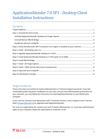
Modeling ArchitectureFive modeling levels are presented in the following illustration. Notice that the DBMS modelcan be at either an Area Level scope, or a Project Level scope. It is not uncommon to havesingle ERD and KB models for a business, and multiple DBMS models. You can have oneDBMS model for each implementation environment, and another set within that environment for projects that do not share databases. In an ideal situation, there is a set of AreaLevel scope DBMS models. One Area Level scope DBMS model for each environment, withcomplete data sharing across all projects in that environment.The models fall into two categories:20
LogicalPhysical21
Logical ModelsThere are three levels of logical models that are used to capture business informationrequirements:Entity Relationship diagramKey-Based modelFully-Attributed modelThe Entity Relationship diagram and the Key-Based models are also known as area data models. They often cover a wide business area that is larger than the business chooses toaddress with a single automation project. In contrast, the Fully-Attributed model is a projectdata model. Typically it describes a portion of an overall data structure intended for supportby a single automation effort.22
Entity Relationship DiagramThe Entity Relationship diagram (ERD) is a high-level data model that shows the major entities and relationships, which support a wide business area. An ERD is primarily a presentation or discussion model.The ERD objective is to provide a view of business information requirements to satisfy theneed for broad planning for development of its information system. These models are notdetailed (only major entities are included), and not much detail, if any, on attributes. Manyto-many (nonspecific) relationships are allowed, and keys are generally not included.23
Key-Based ModelA key-based (KB) model describes the major data structures, which support a wide businessarea. All entities and primary keys are included with sample attributes.The objective of the KB model is to provide a broad business view of data structures andkeys required to support the area. A KB model provides a context where detailed implementation level models can be constructed. The model covers the same scope as the AreaERD, but exposes more of the detail.24
Fully-Attributed ModelA fully-attributed (FA) model is a third normal form data model that includes all entities,attributes, and relationships required by a single project. The model includes entity instancevolumes, access paths and rates, and expected transaction access patterns across the datastructure.25
Physical ModelsTwo levels of physical models exist for an implementation project:Transformation modelDBMS modelThe physical models capture all of the information that data architects and database administrators require to implement a logical model as a database system. The Transformationmodel is also a project data model that describes a portion of an overall data structure supported by a single automation effort. Individual projects within a business area are supported, allowing the modeler to separate a larger area model into subject areas. Subjectareas can be developed, reported on, and generated to the database in isolation from thearea model and other subject areas in the model.This section contains the following topicsTransformation ModelDBMS Model26
Transformation ModelThe objectives of the Transformation model include:Provide the database administrator with sufficient information to create an efficientphysical databaseProvide a context for the definition and recording of the data elementsHold the records that form the database in the data dictionaryHelp the application team select a physical structure for the programs that will accessthe data.During the development effort, the model can also provide the basis for comparing the physical database design against the original business information requirements to:Demonstrate that the physical database design adequately supports those requirements.Document physical design choices and their implications, such as what is satisfied, andwhat is not.Identify database extensibility capabilities and constraints.27
DBMS ModelThe Transformation model directly translates into a DBMS model, which captures the physical database object definitions in the RDBMS schema or database catalog. The schema generation function directly supports this model. Primary keys become unique indexes.Alternate keys and inversion entries can also become indexes. Cardinality can be enforcedeither through the referential integrity capabilities of the DBMS, application logic, or afterthe fact detection and repair of violations.28
Logical ModelsThis section contains the following topicsConstructing a Logical ModelEntity Relationship DiagramLogical Model Design ValidationData Model Example29
Constructing a Logical ModelThe first step in constructing a logical model is developing the Entity Relationship diagram(ERD), a high-level data model of a wide business area. An ERD is made up of three mainbuilding blocks: entities, attributes, and relationships. A diagram can be viewed as a graphical language for expressing statements about your business. Entities are the nouns, attributes are the adjectives or modifiers, and relationships are the verbs. Building a data modelis simply a matter of putting together the right collection of nouns, verbs, and adjectives.The objective of the ERD is to provide a broad view of business information requirementssufficient to plan for development of the business information system. ERD models are notdetailed (only major entities are included) and there is not much detail, if any, about attributes. Many-to-many (nonspecific) relationships are allowed and keys are generally notincluded. An ERD model is primarily a presentation or discussion model.An ERD can be divided into subject areas, which are used to define business views or specificareas of interest to individual business functions. Subject areas help reduce larger modelsinto smaller, more manageable subsets of entities that can be more easily defined and maintained.Many methods are available for developing the ERD. These range from formal modeling sessions to individual interviews with business managers who have responsibility for wideareas.30
Entity Relationship DiagramThe Entity Relationship diagram (ERD) is a high-level data model that shows the major entities and relationships, which support a wide business area. An ERD is primarily a presentation or discussion model.The ERD objective is to provide a view of business information requirements to satisfy theneed for broad planning for development of its information system. These models are notdetailed (only major entities are included), and not much detail, if any, on attributes. Manyto-many (nonspecific) relationships are allowed, and keys are generally not included.31
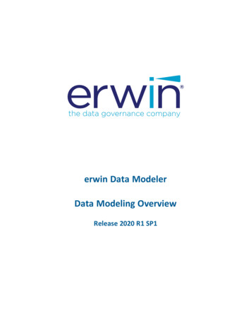
Entities and Attributes DefinedAn entity is any person, place, thing, event, or concept about which information is kept.More precisely, an entity is a set or collection of like individual objects known as instances.An instance (row) is a single occurrence of a given entity. Each instance must have an identity distinct from all other instances.In the preceding illustration, the CUSTOMER entity represents the set of all the possible customers of a business. Each instance of the CUSTOMER entity is a customer. You can listinformation for an entity in a sample instance table, such as is shown in the following illustration:CUSTOMERcustomer idcustomer namecustomer address10001Ed GreenPrinceton, NJ10011Margaret HenleyNew Brunswick, NJ10012Tomas PerezBerkeley, CA17886Jonathon WaltersNew York, NY10034Greg SmithPrinceton, NJEach instance represents a set of facts about the related entity. In the preceding table, eachinstance of the CUSTOMER entity includes information about the customer id,customer name, and customer address. In a logical model, these properties are known asthe attributes of an entity. Each attribute captures a single piece of information about theentity.You can include attributes in an ERD to describe the entities in the model more fully, asshown in the following illustration:32
33
Logical RelationshipsRelationships represent connections, links, or associations between entities. They are theverbs of a diagram that show how entities relate to each other. Easy to understand ruleshelp business professionals validate data constraints and ultimately identify relationship cardinality.Examples of one-to-many relationships:A TEAM has many PLAYERsA PLANE FLIGHT transports many PASSENGERsA DOUBLES TENNIS MATCH requires exactly 4 PLAYERsA HOUSE is owned by one or more OWNERsA SALESPERSON sells many PRODUCTsIn all of these cases, the relationships are chosen so that the connection between the twoentities is what is known as one-to-many. A one-to-many means that one (and only oneinstance) of the first entity is related or connected to many instances of the second entity.The entity on the one-end is known as the parent entity. The entity on the many-end isknown as the child entity.Relationships are displayed as a line connecting two entities, with a dot on one end, and averb phrase written along the line. In the previous examples, the verb phrases are the wordsinside the brackets, such as sells . The following figure shows the relationship betweenPLANE FLIGHTs and PASSENGERs on that flight:34
Many-to-Many RelationshipsIn key-based and fully-attributed models, relationships must relate zero or one instances in aparent entity to a specific set of instances in a child entity. As a result of this rule, many-tomany relationships that were discovered and documented in an ERD or earlier modelingphase must be broken down into a pair of one-to-many relationships.This figure shows a many-to-many relationship between STUDENTs and COURSEs. If you didnot eliminate the many-to-many relationship between COURSE and STUDENT, the key ofCOURSE would be included in the key of STUDENT, and the key of STUDENT would beincluded in the key of COURSE. Since COURSEs are identified by their own keys, and likewisefor STUDENTs this, creates an endless loop.You can eliminate a many-to-many relationship by creating an associative entity. In the following figure, the many-to-many relationship between STUDENT and COURSE is resolved byadding the COURSE-ROSTER entity.COURSE-ROSTER is an associative entity, which means it is used to define the associationbetween two related entities.Many-to-many relationships often hide meaning. In the diagram with a many-to-many relationship, you know that a STUDENT enrolls in many COURSEs, but no information is includedto show how. When you resolve the many-to-many relationship, you see not only how the35
entities are related, but uncover additional information, such as the course-time, whichalso describes facts about the relationship.Once the many-to-many relationship is resolved, you are faced with the requirement toinclude relationship verb phrases that validate the structure. There are two ways to do this:construct new verb phrases or use the verb phrases as they existed for the many-to-manyrelationship. The most straightforward way is to continue to read the many-to-many relationship, through the associative entity. Therefore, you can read A STUDENT enrolls in many COURSEs and A COURSE is taken by many STUDENTs. Many modelers adopt thisstyle for constructing and reading a model.There is another style, which is equally correct, but a bit more cumbersome. The structureof the model is exactly the same, but the verb phrases are different, and the model is readin a slightly different way:You would read: A STUDENT enrolls in a COURSE recorded in one or more COURSEROSTERs, and A COURSE is taken by a STUDENT recorded in one or more COURSEROSTERs.Although the verb phrases are now quite long, the reading follows the standard pattern; reading directly from the parent entity to the child.Whichever style you choose, be consistent. Deciding how to record verb phrases for manyto-many relationships is not too difficult when the structures are fairly simple, as in theseexamples. However, this can become more difficult when the structures become more complex, such as when the entities on either side of the associative entities are themselves associative entities, which are there to represent other many-to-many relationships.36
Logical Model Design ValidationA data model exposes many of the business rules that describe the area being modeled.Reading the relationships helps you validate that the design of the logical model is correct.Verb phrases provide a brief summary of the business rules embodied by relationships.Although they do not precisely describe the rules, verb phrases do provide an initial sense ofhow the entities are connected.If you choose your verb phrases correctly, you can read a relationship from the parent to thechild using an active verb phrase.Example:A PLANE FLIGHT transports many PASSENGERs.Verb phrases can also be read from the perspective of the child entity. You can often readfrom the child entity perspective using passive verb phrases.Example:Many PASSENGERs are transported by a PLANE FLIGHT.Verifying that each verb phrase in the model results in valid statements is a good practice.Reading your model back to the business analysts and subject matter experts is a good wayto verify that it correctly captures the business rules.37
Data Model ExampleThe following model of a database was constructed for a
Data Modeling Data modeling Data modeling is the process of describing information structures and capturing busi-ness rules to specify information system requirements. Data models represent a bal-ance between the specific needs of an RDBMS implementation project, and the general needs of the business area that requires it.