Transcription
TCG SpecificationTPM 2.0 Mobile Command Response BufferInterfaceFamily “2.0”Level 00 Revision 1216 December 2014Contact: admin@trustedcomputinggroup.orgTCG PublishedCopyright TCG 2014TCG
TPM 2.0 Mobile Command Response Buffer InterfaceCopyright 2014 Trusted Computing Group, Incorporated.Disclaimers, Notices, and License TermsTHIS SPECIFICATION IS PROVIDED "AS IS" WITH NO WARRANTIES WHATSOEVER, INCLUDINGANY WARRANTY OF MERCHANTABILITY, NONINFRINGEMENT, FITNESS FOR ANY PARTICULARPURPOSE, OR ANY WARRANTY OTHERWISE ARISING OUT OF ANY PROPOSAL, SPECIFICATIONOR SAMPLE.Without limitation, TCG disclaims all liability, including liability for infringement of any proprietary rights,relating to use of information in this specification and to the implementation of this specification, and TCGdisclaims all liability for cost of procurement of substitute goods or services, lost profits, loss of use, loss ofdata or any incidental, consequential, direct, indirect, or special damages, whether under contract, tort,warranty or otherwise, arising in any way out of use or reliance upon this specification or any informationherein.This document is copyrighted by Trusted Computing Group (TCG), and no license, express or implied, isgranted herein other than as follows: You may not copy or reproduce the document or distribute it toothers without written permission from TCG, except that you may freely do so for the purposes of (a)examining or implementing TCG specifications or (b) developing, testing, or promoting informationtechnology standards and best practices, so long as you distribute the document with these disclaimers,notices, and license terms.Contact the Trusted Computing Group at www.trustedcomputinggroup.org for information on specificationlicensing through membership agreements.Any marks and brands contained herein are the property of their respective owners.Family “2.0”16 December 2014TCG PublishedCopyright TCG 2014Page iiLevel 00 Revision 12
TPM 2.0 Mobile Command Response Buffer InterfaceAcknowledgementsTCG acknowledges the following contributors to this specification:Alec Brusilovsky, Andreas Fuchs, Andrew Martin, Ariel Segall, Atul Shah, Carlin Covey, Carlton Northern,Cedric Colnot, David Wooten, Dean Liberty, Emily Ratliff, Gilles Peskine, Graeme Proudler, Hadi Nahari,Hervé Sibert, Ira McDonald, Janne Uusilehto, John Mersh, John Padgette, Joshua Schiffman, KathleenMcGill, Michael Chan, Michael Peck, Niall O’Donoghue, Paul England, Paul Waller, Rob Spiger, RonaldAignerFamily “2.0”Level 00 Revision 12TCG PublishedCopyright TCG 2014Page iii16 December 2014
TPM 2.0 Mobile Command Response Buffer InterfaceCONTENTS1Scope and Audience . 11.11.21.31.41.51.62Interface Overview . 32.12.22.33Introduction . 3Basic Protocol . 3Discoverability . 4Structures . 53.13.23.33.43.53.63.73.83.93.104Key words . 1Statement Type. 1References. 1Document structure . 1Glossary . 2Abbreviated Terms . 2Control Area . 5Request. 5Status . 6Cancel . 6Start . 7Interrupt Control . 7Command Size . 7Command Address . 7Response Size . 8Response Address . 8Examples of CRB Interface State Transitions . 94.14.2CRB Interface State Transition with all states . 9CRB Interface State Transition with “Ready” and “Command Execution” states . 9Family “2.0”16 December 2014TCG PublishedCopyright TCG 2014Page ivLevel 00 Revision 12
TPM 2.0 Mobile Command Response Buffer Interface1Scope and AudienceThe Trusted Computing Group TPM 2.0 [1] specification defines a Trusted Platform Module (TPM).This specification defines an interface between a TPM and software. This interface is theCommand/Response Buffer Interface (CRB). The CRB design is intended to work with a large number ofhardware implementation options. With this interface, it is possible to write a driver that can interact with aTPM whether it is implemented as a discrete component on a peripheral bus or in an execution mode in aProtected Environment.Designers, developers and implementers of Trusted Computing technologies in mobile platforms are thetarget audience for this specification.1.1Key wordsThe upper-case key words “SHALL,” “SHOULD” and “MAY” in this document indicate normative statementsand are to be interpreted as described in [3].1.2Statement TypeThere are two distinctive kinds of text throughout this reference architecture: informative comments andnormative statements.Most of the content consists of informative comments that explain why the architecture is as defined, butwhich do not constrain implementation in any specific way.Normative statements SHALL be obeyed if a standards compliant implementation is to be created.Normative statements are indicated by the presence in a statement of any of the upper-case key wordslisted in Section 1.1.1.3References[1] Trusted Computing Group, Trusted Platform Module, Version 2.0, Parts 1-4, 2013[2] ACPI General Specification, version 1.1[3] IETF, RFC 2119, March 19971.4Document structureThis document is divided and ordered into sections so that concepts are introduced in a logical sequence.Section 1.5 contains a reference glossary defining the terms and definitions used throughout thespecification.Section 2 contains an introduction to the protocol.Section 3 provides definitions for data structures used in the protocol.Section 4describes possible implementations of the protocol.Family “2.0”Level 00 Revision 12TCG PublishedCopyright TCG 2014Page 116 December 2014
TPM 2.0 Mobile Command Response Buffer Interface1.5GlossaryGlossary TermDescriptionBufferData structure used for transport to and from the TPM.CLEARBit with a value of zero (0), or the action of causing a bit to have thevalue of zero (0).CommandThe values sent to the TPM to indicate the operation to beperformed.Failure modeMode in which the TPM returns TPM RC FAILURE in response toall commands except TPM2 GetTestResult() orTPM2 GetCapability().OctetEight bits of data.ResponseValues returned by the TPM when it completes processing of acommand.SETBit with value of one (1), or the action of causing a bit to have thevalue of one (1).TPM Device ResetResetting the TPM internal state due to TPM Init.Trusted Platform ModuleTPMImplementation of the TPM Library Specification; Family 2.0; Level00; Revision 103 or later.1.6Abbreviated TermsAbbreviated TermDescriptionACPIAdvanced Configuration and Power InterfaceCPUCentral Processing UnitCRBCommand Response Buffer (interface)FIFOFirst-In First-Out. Refers to a pipeline access to the TPM device.Octets are written to the pipeline and are read in the order they havebeen written.MSOMost Significant Octet.OSOperating SystemRSARivest, Shamir and AdlemanTCGTrusted Computing GroupTPMTrusted Platform ModuleTPMPrefix for an indication passed from the system interface of the TPMto a Potected Capability defined in the TPM Library SpecificationTPM2Prefix for a command defined in the TPM Library SpecificationFamily “2.0”16 December 2014TCG PublishedCopyright TCG 2014Page 2Level 00 Revision 12
TPM 2.0 Mobile Command Response Buffer Interface2Interface OverviewSoftware interacting with the TPM often directs commands through a TPM driver. The TPM driver performsthe actual device interface access, which in the case of this specification, implies the manipulation of theCommand and Response Buffer (CRB) interface.The terms “software” and “TPM driver” are used interchangeably.2.1IntroductionThe basic concept for the CRB interface is that the TPM’s command and response buffers are defined aslinear ranges of memory. Software may put data in the TPM’s command buffer by writing to consecutiveaddresses in the processor’s address space. Similarly, the driver may read data from the TPM’s responsebuffer by reading from consecutive addresses in the processor’s linear address space.Software is restricted to writing/reading the bytes of the command/response buffer to consecutiveaddresses. Therefore, the data is presented to the TPM in a consumable form whether thecommand/response buffer is actual linear memory or a hardware FIFO.The control flow for the CRB is a simple handshake through a memory-mapped control structure. Thiscontrol structure is also defined such that it can either be in actual memory or be hardware registers on adiscrete TPM.Including the control structure, the three memory areas comprise the entirety of the CRB. There are noconstraints on how those three memory areas are provided. They can all be in system RAM, or all be indevice memory, or any combination. The control structure needs to occupy a unique address space but thecommand and response buffers may overlap (or be the same).The interface definition provides extensions for power management of the TPM for those systems that needthis capability. The power management protocol is also defined for simplicity so that the complexities of thedevice power management are largely hidden from the driver while maintaining a large degree of flexibilityin the device’s implementation of power management (if any).2.2Basic ProtocolThe TPM processes one command at a time. Software will place the command to be executed into theCommand buffer and SET Start in the command structure. The TPM will detect that Start is SET andprocesses the command in the Command buffer. The TPM finishes command processing by putting itsresponse in the Response buffer and clearing Start.While Start is SET, the driver will not access the command or response buffer. While Start is CLEAR, theTPM will not access the command or response buffer.An implementation may use polling or interrupts to signal when Start changes. If interrupts are used, theTPM would receive an interrupt when Start is SET and the driver would receive an interrupt when Start isCLEAR. The TPM may use interrupts and the driver may use polling, or vice versa.Power management is added by including an Idle/Ready handshake. When the driver has nothing for theTPM to do, it SETS goIdle to indicate to the TPM that there is currently no work to be done. The TPM maypower down. If it does, it will SET Idle. When the driver has a command for the TPM, it will SET cmdReadyand wait for Status to CLEAR. When Status is CLEAR, the driver may start loading the Command buffer.Details of the protocols are in the following sections.Family “2.0”Level 00 Revision 12TCG PublishedCopyright TCG 2014Page 316 December 2014
TPM 2.0 Mobile Command Response Buffer Interface2.3DiscoverabilityTPM support for the CRB interface depends on the TPM implementation. For systems that support ACPI,a possible way to identify a TPM with the CRB interface is the Advanced Configuration and Power Interface(ACPI) table for TPM 2.0, as defined in the TCG ACPI General Specification, version 1.1.The ACPI table contains a field to identify the communication interface for the TPM 2.0 devices. It alsocontains the address of the Control Area that further allows the discovery of command and response bufferaddresses.Other TPM implementations may publish the Control Area at a fixed address. Because the control areacontains fields for the addresses of command and response buffer, these implementations only need tostandardize the location of the Control Area.Family “2.0”16 December 2014TCG PublishedCopyright TCG 2014Page 4Level 00 Revision 12
TPM 2.0 Mobile Command Response Buffer Interface33.1StructuresControl AreaThe Control Area structure contains status fields as well as physical addresses and sizes of the commandand response buffer.FieldByte LengthOffsetDescriptionRequest40016Used to control power state transition.Status40416Used to indicate a status.Cancel40816Used to abort command processing.Start40C16Used to indicate that a command is available forprocessing.Interrupt Control81016Reserved.Command Size41816Size of the Command Buffer.Command Address81C16This field contains the physical address of theCommand Buffer.Response Size42416Size of the Response Buffer.Response Address82816This field contains the physical address of theResponse Buffer.Table 1: CRB Control Area LayoutThe CRB interface does not prescribe a specific access pattern to the fields of the Control Area. The fieldshave to be neither read nor written as a whole. Access may be smaller than the field size and can berandom.3.2 RequestThis field can be used to negotiate power state transitions between software and the TPM. Software setsthis field to indicate the request to transition into a different power state. The TPM will reflect the currentstate in the Status field. If necessary, software may trigger an interrupt to indicate the state change requestto the TPM.BitNameDescription0cmdReadySET by software to transition TPM from Ready state into Idle state.1goIdleSET by software to transition TPM from Idle state into Ready state.ReservedReserved.31:2Table 2: Bit layout of CRB Request fieldSoftware uses the Request field to indicate the requested behavior from the TPM. When software SETsthe goIdle bit, it indicates that it finished accessing the Command and Response Buffer for now. The TPMmay go into the “Idle” state. It may use this state to conserve power or perform other tasks. To signal the“Idle” state, the TPM will SET tpmIdle in Status and CLEAR goIdle in Request.Software will SET cmdReady to indicate that that the TPM should prepare to receive the next command.To signal that it is ready to receive the next command (the “Ready” state), the TPM will CLEAR tpmIdle inStatus and CLEAR cmdReady in Request.Family “2.0”Level 00 Revision 12TCG PublishedCopyright TCG 2014Page 516 December 2014
TPM 2.0 Mobile Command Response Buffer InterfaceSoftware should not use Request with TPM implementations that do not support a low power state (the“Idle” state).The initial value of this field (when software has first access to the control area) is undetermined. The stateof the TPM is reflected in Status. When software uses Request, it will write the whole field when SETting abit in this field. It is good practice if the firmware sets this field to zero before making it visible to the TPMdriver.Some platforms may be unable to trigger requests based on changes of Request and may require anadditional notification. One possible implementation is the use of an ACPI method (see TCG ACPI GeneralSpecification version 1.1). For platforms without ACPI, an alternative notification such as interrupts couldbe used.3.3 StatusThis field is used to communicate TPM state to software. If Status is CLEAR, the TPM is in the “Ready”state and is able to receive a command.BitNameDescription0ErrorSET by the TPM in case of unrecoverable error.1tpmIdleSET by the TPM if in low power state.ReservedReserved.31:2Table 3: Bit layout of CRB Status fieldtpmIdle is SET by the TPM to indicate to software that the TPM is in the “Idle” state. Software has to SETcmdReady in Request to initiate a transition of the TPM into the “Ready” state.Error indicates an unrecoverable error condition in the TPM that cannot be communicated by the errorreturn codes defined in the TPM Library Specification. No assumption about the state of the TPM shouldbe made when Error is SET.This field should reflect the state of the TPM when the Control Area is initialized, for instance by firmwarebefore making it visible to the TPM driver.3.4 CancelSoftware may use Cancel to request that TPM processing of the currently executing command beterminated.Bit031:1NameDescriptionCancelSET by software to request cancelation of the current command.ReservedReserved.Table 4: Bit layout of CRB Cancel fieldWhen Cancel is SET by software and the TPM is executing a command, the TPM will stop executing thecurrent command at the earliest convenient point, that is, when the TPM has the ability to check Cancel.For most commands, it is expected that the TPM will complete the command and provide a normalresponse. For commands that are long-running (for example, RSA key generation), the TPM may exitcommand execution and return a TPM response of TPM RC Cancelled.Family “2.0”16 December 2014TCG PublishedCopyright TCG 2014Page 6Level 00 Revision 12
TPM 2.0 Mobile Command Response Buffer InterfaceCancel has only meaning while Start is SET. Software should CLEAR Cancel when Start is CLEAR, forinstance before SETTING Start, that is, before issuing a command.Cancel should be CLEAR when the Control Area is initialized, for instance by firmware before making itvisible to the TPM driver.Some platforms may be unable to trigger cancelation of TPM commands based on changes of Cancel andmay require an additional notification. One possible implementation is the use of an ACPI method (seeTCG ACPI General Specification version 1.1). For platforms without ACPI, an alternative notification suchas interrupts could be used.3.5 StartSoftware will SET this field to indicate to the TPM that a new command has been placed in the Commandbuffer. The TPM will CLEAR Start when it completes processing a command.Bit031:1NameDescriptionStartSET by software to signal that Command Buffer contains a newcommand. CLEARED by the TPM when a response to thecommand is in the Response Buffer.ReservedReserved.Table 5: Bit layout of CRB Start fieldStart is SET by software to signal to the TPM that it should start execution of the TPM command that iscurrently in the Command Buffer. The TPM changes into the “Command Execution” state.The TPM will CLEAR Start when a response is ready in the Response Buffer. The response will containthe result of the command or a TPM error response. The TPM transitions from “Command Execution” to“Command Completion” (or “Ready” if “Command Completion” is not supported).Some platforms may not be able to trigger TPM commands based on changes of Start and may require anadditional notification. One possible implementation is the use of an ACPI method (see TCG ACPI GeneralSpecification version 1.1). For platforms without ACPI, an alternative notification such as interrupts couldbe used. Some platforms may actively transfer the current CPU into the TPM execution environment andreturn to the calling software when the response is in the Response Buffer.Start should be CLEAR when the Control Area is initialized.3.6 Interrupt ControlPlatforms that support the generation of interrupts or notifications by the TPM may use this field to definethe interface to subscribe to these interrupts.3.7 Command SizeThis is the size of the Command buffer in bytes.The value of Command Size field should be chosen such that the largest command that can be issued forthe specific TPM implementation fits into the command buffer.3.8 Command AddressThis is the physical address of the command buffer. Software will write the TPM command to be executedto this address.Family “2.0”Level 00 Revision 12TCG PublishedCopyright TCG 2014Page 716 December 2014
TPM 2.0 Mobile Command Response Buffer InterfaceSoftware should not write a command larger than “Command Size”.Software should not write to this memory area unless Start is CLEAR. System hardware might preventwriting to this address if Start is SET.3.9 Response SizeThis is the size of the Response Buffer in bytes.The value of Response Size field should be chosen such that the largest response that can be returnedfrom the specific TPM implementation fits into the response buffer.3.10Response AddressThis is the physical address of the Response Buffer. Software will read the response to the last TPMcommand from this address.Software should not read a response larger than “Response Size”.Software should only read a response after Start changed from SET to CLEAR and Error is CLEAR.Family “2.0”16 December 2014TCG PublishedCopyright TCG 2014Page 8Level 00 Revision 12
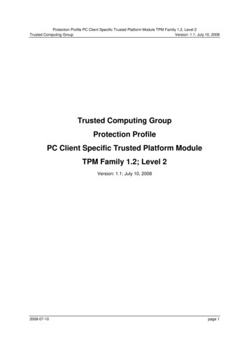
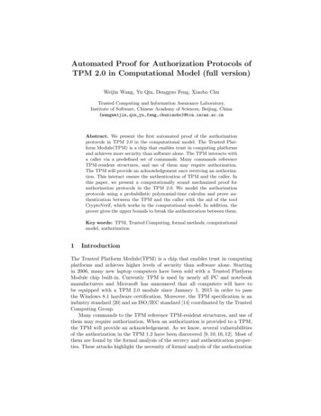
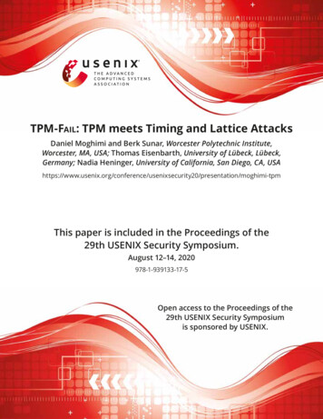
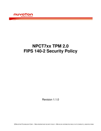
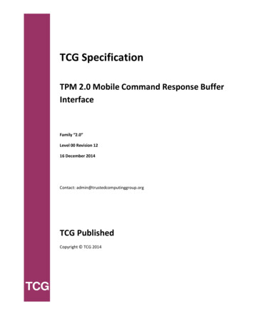
TPM 2.0 Mobile Command Response Buffer Interface4Examples of CRB Interface State TransitionsThe following sample state-transition diagrams illustrate possible execution flows.4.1 CRB Interface State Transition with all statesAn overly simplified possible state transition might look like Figure 1: it does not cover all of the possiblestate transitions, but walks through sending a TPM command with a TPM implementation that supports the“Idle”, “Ready”, “Command Reception”, “Command Execution”, and “Command Completion” CommandExecution(3) SW sets StartFigure 1: simplified CRB state transition with “Idle” stateAssuming the TPM is in the “Idle” state, step (1) transitions the TPM from “Idle” to “Ready”.When the TPM is in the “Ready” state it can receive a command, which is done in steps (2) and (2b).When software finishes copying the command into the Command Buffer, it will SET Start (step (3)).The TPM will start execution of the command, which completes when the TPM CLEARs Start in step (4).Now software can read the response in step (5).When software is done with the response, it can signal the TPM that it may go into “Idle” state again in step(6).4.2 CRB Interface State Transition with “Ready” and “Command Execution” statesThe following state transition diagram (Figure 2) represents the interaction for normal TPM commandexecution if “Idle”, “Command Reception”, and “Command Completion” are not implemented by the TPM.Family “2.0”Level 00 Revision 12TCG PublishedCopyright TCG 2014Page 916 December 2014
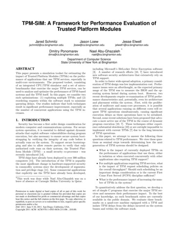
TPM 2.0 Mobile Command Response Buffer InterfaceReady(4, 5) TPM clears Start;SW reads response(2, 3) SW writescommand andsets StartCommandExecutionFigure 2: simplified CRB state transition without “Idle” stateIf a TPM does not support the “Idle” state, steps (1) and (6) can be eliminated from the state transitiondiagram in Figure 1.If the TPM furthermore cannot distinguish between the “Ready” state and “Command Reception” or“Command Completion”, steps (2) and (3), and steps (4) and (5) can be combined respectively.When the TPM is in the “Ready” state, that is, Start is CLEAR, software may write a command to theCommand Buffer or read a response from the Response Buffer.When software SETs Start, the TPM starts executing the command in the Command Buffer. The TPM willCLEAR Start after it has placed the response into the Response Buffer.If Command Buffer and Response Buffer point to the same memory, software has to manage the“Command Reception” and “Command Completion” states to know when the buffer contains a response ora command.Family “2.0”16 December 2014TCG PublishedCopyright TCG 2014Page 10Level 00 Revision 12
TPM 2.0 Mobile Command Response Buffer Interface . The Trusted Computing Group TPM 2.0 [1] specification defines a Trusted Platform Module (TPM). This specification defines an interface between a TPM and software. This interface is the . FIFO First-In First-Out. Refers to a pipeline access to the TPM device.