Transcription
Form S70-400 SPL (JUL 2006)SERVICE PARTS LISTFile:Replaces:Dist:SERVICE MANUAL - Section 70S70-400 SPL (AUG 2002)3, 3a, 3b, 3cService Parts ListRXFROTARY SCREW COMPRESSOR UNITSWITHQUANTUM LX CONTROLMODELS: RXF 12 through 101Please check www.frickcold.com for the latest version of this publication.
S70-400 SPL (JUL 2006)Page 2RXF ROTARY SCREW COMPRESSOR UNITSERVICE PARTS LISTHOW TO USE SERVICE PARTS LISTThis Service Parts List is for standard Frick RXF, Rotary Screw Compressor Units, Models 12—101. Units built with specialoptions, modifications, or conversions are not taken into consideration.This Service Parts List provides identification for detail parts by Figure and Index Number, Item Number and Description. Todetermine correct replacement item, locate item on Figure 1, 2, etc., note index number, refer to corresponding index numberin parts list for item number and description. Quantity per assembly is located in QTY. column. Unit of measure is always “each”unless specified otherwise in Quantity column. When Ref. is in QTY. column, this means that the Item Number is for informationonly and is not necessarily a service replacement part. Contact Baltimore Parts Center for more information. REV. (Revision)column tells the level of the engineering drawing used here. The P & I REF. column gives the number of the item as shown onthe Piping and Instrumentation drawing.The Numerical Parts List can be used to locate a specific item in the Service Parts List. Look for the part by Frick Item Numberand it will refer you to the Figure and Index Number where it is located.Abbreviations found in this manual include:A/R .As RequiredSW . Socket WeldHW .Hand WheelTSOC . Thermosyphon Oil CoolerRef. .ReferenceWIL . Weld-In-LineSC .Seal CapWCOC . Water Cooled Oil CoolerThe Unit Data Plate listing model/serial number etc., is attached to the rear motor mounting bracket, when facing the motor endopposite the coupling.NOTE: PLEASE PROVIDE FRICK ORDER NUMBER, UNIT MODEL NUMBER, AND UNIT SERIAL NUMBER WHEN REQUESTING A QUOTATION OR PLACING AN ORDER. FAILURE TO INCLUDE THIS INFORMATION MAY DELAY PROCESSING OFYOUR REQUEST.TABLE OF CONTENTSHOW TO USE SERVICE PARTS LIST . 2RECOMMENDED SPARE PARTS - CURRENT STANDARD DESIGN . 3Figure 1. General Arrangement, Typical, RXF 12—50. . 4Figure 2. General Arrangement, Typical, RXF 58—101. . 6Figure 3. Compressor, XJF 95 & 120, RXF 12—50 (XJF 95 Shown). . 8Figure 4. Compressor, Typical, XJF 151, RXF 58—101. 10Figure 5. Oil Separator, Typical, RXF 12—50. . 12Figure 6. Oil Separator, Typical, RXF 58—101. . 14Figure 7. Oil Cooler Piping, Typical, RXF 12—50, WCOC Shown. . 18Figure 8. Plate Oil Cooler Piping, Typical, RXF 12—50. . 22Figure 9. Plate Oil Cooler Piping, RXF 58—101. . 24Figure 10. Oil Pump and Piping, Typical, RXF 12—50. 28Figure 11. Liquid Injection Piping, Typical. . 32Figure 12. Piping, Pump & Liquid Injection, RXF 58—101. . 36Figure 13. Oil Filter, Standard, RXF 58—101. . 38Figure 14. Dual Oil Filter, Typical, RXF 58—101. 39Figure 15. Economizer Kit, Typical. . 40Figure 16. Transducer Piping Assembly. . 41Figure 17. Drive Coupling. . 41Figure 18. 2-1/2—4" Discharge Stop/Check Valve, Current (Danfoss). . 42Figure 19. Wiring Harness Assembly, RXF 58 — 101. . 44FRICK FLANGE GASKETS. 46FRICK COMPRESSOR OILS . 46FRICK BLUE PAINT . 46ADAPTERS - STRAIGHT THREAD TO NPTF . 47Figure 20. Piping and Instrumentation w/o Oil Pump, RXF 12—50. . 48Figure 21. Piping and Instrumentation w/o Oil Pump, RXF 58—101. . 50Figure 20. RXF 12—19, XJF 95 Port Locations. . 52Figure 21. RXF 24—50, XJF 120 Port Locations. . 53Figure 22. RXF 58—101, XJF 151 Port Locations & O-rings. 54Numerical Parts List . 55100 CV Avenue P.O. Box 997 Waynesboro, Pennsylvania USA 17268-0997Phone: 717-762-2121 FAX: 717-762-8624 www.frickcold.com
RXF ROTARY SCREW COMPRESSOR UNITSERVICE PARTS LISTS70-400 SPL (JUL 2006)Page 3RECOMMENDED SPARE PARTS - CURRENT STANDARD DESIGNDESCRIPTIONUNIT:Sensor, Temperature ProbeTransducer, Pressure, 0—200 PSIATransducer, Pressure, 0—500 PSIAValve, Solenoid, Yuken 120/60 & 110/50Coil For 951A0114H01 AboveSeal Kit for 951A0114H01 AboveValve, Solenoid, 120VAC, w/DIN ConnectorCoil For 951A0095G01Coil, Solenoid Valve, 120VACSolenoid ValveLinear Transmitter, Short Stroke (Slide Valve Indicator)Heater, Oil, 500W, 120VACHeater, Oil, 500W, 120VACSwitch, Liquid Level w/2" Reducing Bushing (See Fig. 5)Oil Level SensorFilter, CoalescingFilter, Demistifier , CoalescingFilter, Demistifier , CoalescingFilter, Demistifier , CoalescingGasket, Separator Access CoverGasket, Separator Access CoverGasket, Separator ManwayGasket, Separator ManwayCartridge, Oil Filter, SuperFilter II (Required for 1-2-3 Warranty)Element, Filter, Oil, SuperFilter II (Required for 1-2-3 Warranty)Gasket, for 531A0224H01 aboveKit, Shaft Seal, XJF 95Kit, Shaft Seal, XJF 120Kit, Shaft Seal, XJF 151QTY.MODELITEM ��5058 & 6885 & 043231534M0602G02Note: This list is based on one unit. When stocking for more than one unit, the quantity should be adjustedto meet your individual requirements.For help in identifying valves, see Shutoff Valve Identification Guide S160-800 SPL.For Control Center parts, see Quantum LX Maintenance S90-020 M, Recommended Spare Parts List.
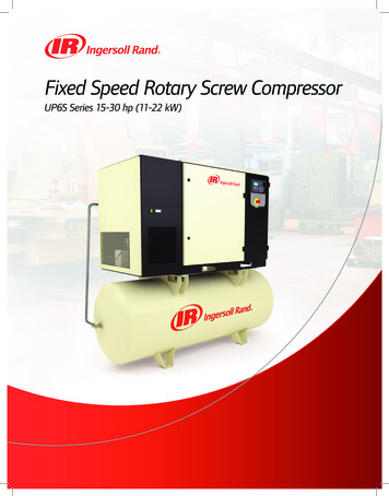
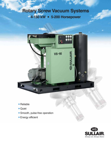
S70-400 SPL (JUL 2006)Page 4RXF ROTARY SCREW COMPRESSOR UNITSERVICE PARTS LISTFigure 1. General Arrangement, Typical, RXF 12—50.
RXF ROTARY SCREW COMPRESSOR UNITSERVICE PARTS LISTFIG. (4)S70-400 SPL (JUL 2006)Page K69535A0356H01980A0012K69RXF 12, R-22 & R-717, Screw Compressor UnitRXF 15 & 19, R-22 & R-717, Screw Compressor UnitRXF 24, R-22 & R-717, Screw Compressor UnitRXF 30 & 39, R-22 & R-717, Screw Compressor UnitRXF 50, R-22 & R-717, Screw Compressor UnitHead, Oil Filter, 1 5/16-12 UN-2B, Straight Thread, O-ringCartridge, Oil Filter, 4-5/8 x 11-5/8", SuperFilter II (1)Valve, Angle, Needle, Seal Cap, 1/4" MPT x 1/4" FPTQuantum LX Control Center (2)Screw Compressor (See Figure 3)Drive Coupling (See Figure 17)Oil Separator and Safety Relief Valve (See Figure 5)Transducer Assembly (See Figure 16)Oil Pump Piping (See Figure 10)Valve, Discharge Stop/Check (See Figure 18)Valve, Angle, SW, SC, 1/2"Spare Parts Kit, Complete, 1/2"Spare Parts Kit, Cone, 1/2"Spare Parts Kit, Packing Gland, 1/2"Spare Parts Kit, Cap & Bonnet, 1/2"Spare Parts Kit, Seal Cap & Gasket, 1/2"Strainer, 1/2" FPTGasket, FlangeGasket, ScreenKit, Screen w/GasketAssembly, Sensor, Temperature (3)Sensor, Temperature, less Well & DINWell onlyDIN Connector (with M3 connection for shielded cable)DIN GasketThermal CompoundValve, WIL, Angle, SC, 2-1/2" Danfoss (See Figure 18)Valve, WIL, Angle, SC, 3" Danfoss (See Figure 18)Valve, WIL, Angle, SC, 4" Danfoss (See Figure 18)Valve, Angle, THD, SC, 3/4", DanfossSpare Parts Kit, Complete, 3/4"Spare Parts Kit, Cone, 3/4"Spare Parts Kit, Packing Gland, 3/4"Spare Parts Kit, Cap & Bonnet, 3/4"Spare Parts Kit, Seal Cap & Gasket, 3/4"Valve, Angle, THD, SC, 1", DanfossSpare Parts Kit, Complete, 1"Spare Parts Kit, Cone, 1"Spare Parts Kit, Packing Gland, 1"Spare Parts Kit, Cap & Bonnet, 1"Spare Parts Kit, Seal Cap & Gasket, 1"Valve, Globe, SW, SC, 1", Danfoss (4)Spare Parts Kit, Complete, 1"Spare Parts Kit, Cone, 1"Spare Parts Kit, Packing Gland, 1"Spare Parts Kit, Cap & Bonnet, 1"Spare Parts Kit, Seal Cap & Gasket, 1"Adapter, 1" FPT x 1" SAEO-ring onlyBushing, Orifice, O-ringO-ring ed for 1-2-3 WarrantySee Quantum LX Maintenance S90-020 M, Recommended Spare PartsSee Figure 5.Optional Oil Filter Isolation ValveP&IREF.NVSTRTE
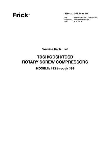
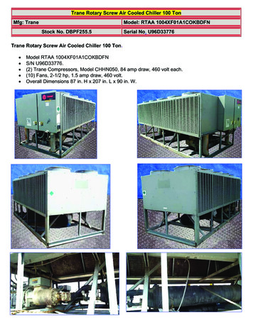
S70-400 SPL (JUL 2006)Page 6RXF ROTARY SCREW COMPRESSOR UNITSERVICE PARTS LISTFigure 2. General Arrangement, Typical, RXF 58—101.
RXF ROTARY SCREW COMPRESSOR UNITSERVICE PARTS LISTFIG. —13—14—15DESCRIPTIONRXF 58 & 68, R-22 & R-717, Screw Compressor UnitRXF 85 & 101, R-22 & R-717, Screw Compressor UnitScrew Compressor (See Figure 4)Coupling, Drive (See Figure 17)Oil Separator and Safety Valve (See Figure 6)Oil Filter (See Figure 13)Quantum LX Control Center (1)Transducer Assembly (See Figure 16)Oil Pump Piping (See Figure 9)Oil Cooler Piping (See Figure 9)Valve, Discharge Stop/Check (See Figure 18)Valve, Angle, Needle, Seal Cap, 1/4" MPT x 1/4" FPTValve, Angle, Seal Cap, 1" DanfossSpare Parts Kit, Complete, 1"Spare Parts Kit, Cone, 1"Spare Parts Kit, Packing Gland, 1"Spare Parts Kit, Cap & Bonnet, 1"Spare Parts Kit, Seal Cap & Gasket, 1"Strainer, 1/2" FPTGasket, FlangeGasket, ScreenKit, Screen w/GasketValve, WIL, Angle, SC, 4", Danfoss (See Fig. 18)(2)Valve, WIL, Angle, SC, 5", Danfoss (See Fig. 18)(2)Assembly, Temperature SensorSensor, Temperature, less WellWell onlyDIN ConnectorDIN GasketThermal CompoundValve, Angle, Seal Cap, 1-1/4", DanfossValve, Angle, Seal Cap, 1-1/2", DanfossSpare Parts Kit, Complete, 1-1/4 & 1-1/2”Spare Parts Kit, Cone, 1-1/4 & 1-1/2”Spare Parts Kit, Packing Gland, 1-1/4 & 1-1/2”Spare Parts Kit, Cap & Bonnet, 1-1/4 & 1-1/2”Spare Parts Kit, Seal Cap & Gasket, 1-1/4 & 1-1/2”(1) See Quantum LX Maintenance S90-020 M, Recommended Spare Parts(2) Not shown, shipped loose.S70-400 SPL (JUL 2006)Page 44444A/R1111111P&IREF.NVSTRTE
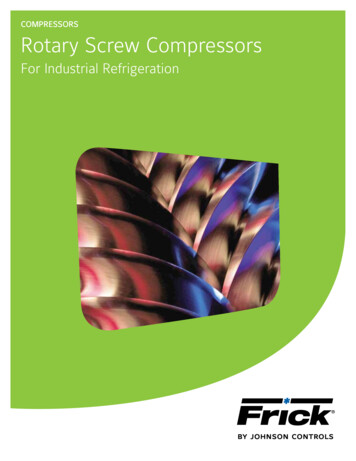
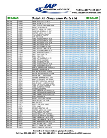
S70-400 SPL (JUL 2006)Page 8RXF ROTARY SCREW COMPRESSOR UNITSERVICE PARTS JF120S*COMPRESSOR PART 305S03534E0305G04534E0305S04* 534E0305G01 is 1800 RPM. 534E0305G04 is 3600 RPM.Figure 3. Compressor, XJF 95 & 120, RXF 12—50 (XJF 95 Shown).
RXF ROTARY SCREW COMPRESSOR UNITSERVICE PARTS LISTFIG. ssor, XJF95S, M, L, RXF 12—19Compressor,
This Service Parts List is for standard Frick RXF, Rotary Screw Compressor Units, Models 12—101. Units built with special options, modifications, or conversions are not taken into consideration. This Service Parts List provides identification for detail parts by Figure and Index Number, Item Number and Description. To determine correct replacement item, locate item on Figure 1, 2, etc .