Transcription
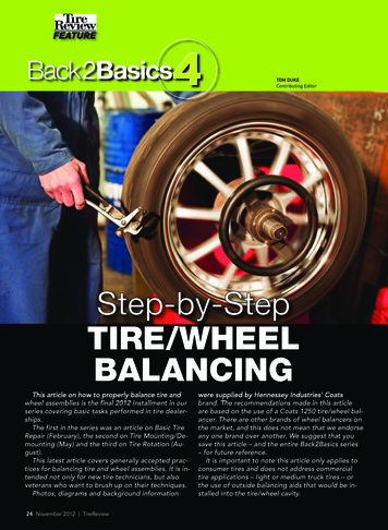
FEATURE4Back 2BasicsTOM DUKEContributing EditorStep-by-StepTIRE/WHEELBALANCINGThis article on how to properly balance tire andwheel assemblies is the final 2012 installment in ourseries covering basic tasks performed in tire dealerships.The first in the series was an article on Basic TireRepair (February), the second on Tire Mounting/Demounting (May) and the third on Tire Rotation (August).This latest article covers generally accepted practices for balancing tire and wheel assemblies. It is intended not only for new tire technicians, but alsoveterans who want to brush up on their techniques.Photos, diagrams and background information24 November 2012 TireReviewwere supplied by Hennessey Industries’ Coatsbrand. The recommendations made in this articleare based on the use of a Coats 1250 tire/wheel balancer. There are other brands of wheel balancers onthe market, and this does not mean that we endorseany one brand over another. We suggest that yousave this article – and the entire Back2Basics series– for future reference.It is important to note this article only applies toconsumer tires and does not address commercialtire applications – light or medium truck tires – orthe use of outside balancing aids that would be installed into the tire/wheel cavity.
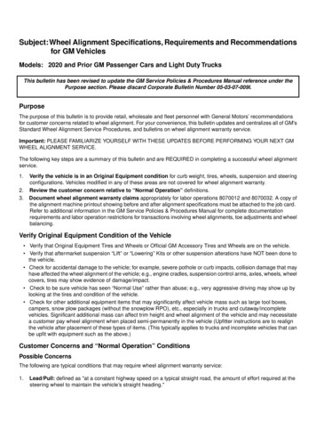
which may cause a half-ounce or sotranslation to the wheel.Tire/wheel assembly balancing isa very basic service, and still a goodprofit center for tire dealers who invest in the necessary equipment.Modern cars and light trucks/SUVs are highly tuned vehicles, andanticipated performance, drivercomfort, fuel economy and tire lifeall can be negatively impacted byeven the slightest imbalance. Fractions of an ounce truly do mattertoday.Current tire/wheel balancers aremuch easier to use than earlier machines or the old-school bubble balancers, with many automatic andcomputer-generated features designed to deliver exceptional balance. Many modern tire/wheelbalancers include features such asdirect drive motors, multiple balancing modes, laser guides, automaticstarting with a cycle of seconds,weight storage bins and automaticstatic balancing.There are a number of reasonswhy you should be checking the balance of the tires/wheels on yourcustomers’ vehicles. The three basictimes when balancing should bedone include:Types Of Balancing When a tire is replaced orrepaired When a balance weight ismoved or falls off When new tires are purchasedTire technicians know that balancing tire/wheel assemblies caneliminate vibration and wobbling.This will improve tire wear, increase fuel mileage and removestress from a vehicle. Vibrationcaused by out-of-balance tires usually occurs at speeds of 50 mph to70 mph. Consumers who onlydrive around town and not on expressways may never notice theirtires are unbalanced, but damage isstill being done.Today’s high-quality tires willhold their balance well unless anoutside force, such as hitting a curbor the loss of a weight, occurs.Technicians also should check tosee if a customer has locking wheellugs in some positions. Some locking lugs are up to 1.5 ounces heavier than conventional lug nuts,In many cases, when a tire ismanufactured, it is inspected forstatic and dynamic balance. Notevery tire, even among the majormakers, is directly tested, though.Tires that don’t measure up in either factor are rejected.Tire manufacturers measurestatic balance by the use of a sensormounted to the spindle assembly,and measure dynamic balance bymounting a tire on a test wheel, accelerating the assembly to 300 rpmor higher and then measuring theforces of imbalance as the tire rotates.In most cases, the old-schoolbubble balancer is a thing of thepast. Dynamic balancers – also referred to as “spin balancers” or“computer balancers” – are themost prevalent piece of equipment.Even among dynamic balancers,though, there are vast differencesin not only features but, more importantly, precision.Dynamic balancers not only determine the location of any imbalance, but also point out the exactamount of counter weight thatmust be added to correct the imbalance. Various available equipmentfeatures can make that an evenmore precise operation.Road force variation balancing isyet another method that has beenin use at the OE level for manyyears. While only in limited use inthe aftermarket, road force variation equipment is becoming increasingly popular as vehiclesensitivity to imbalance becomesever greater.Steps for Balancing aTire/Wheel AssemblyDepending on the equipmentyou have, tire/wheel assembliesare balanced in a number of ways.The steps are outlined as follows ifyou are using one of the more modern, automated machines, like theCoats 1250. These instructions arenot meant to cover every balancingsituation.Before a tire can be balanced, itmust be concentrically seated. YouToday’s balancers can handle almostany car or light truck assemblythat rolls into a bay in a quick andefficient manner.can determine this by measuringthe distance between the moldedrib on the lower sidewall of the tireand the edge of the wheel’s rimflange. The tire must be deflatedand reseated if the distance between the two points is greaterthan 2/32-inch.After ensuring that the beadshave reseated properly, the tireshould be inflated to the recommended pressure.1. Turn your machine OFF thenON, which resets the balancer. Themachine wakes up using standardclip-on wheel weight locations.2. Remove stones/rocks or otherdebris from tread and any weightsalready attached to the wheel.During this process you alsoshould remove any mud, dirt orsnow on the inside of the wheeland make sure that the mountingsurface of the wheel is completelyCleaning the wheel prior tobalancing is important.clean of debris.TireReview.com 25Step-by-Step TIRE/WHEEL BALANCINGBackground OnTire/Wheel Balancing
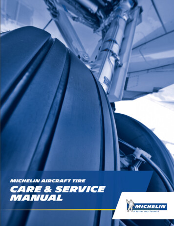
3. Mount a tire/wheel assembly ona balancer that will use standardclip-on wheel weights. Use themost appropriate mounting method. Technicians should be carefulto avoid back injury and shouldseek assistance when lifting aheavy tire/wheel assembly onto abalancing shaft. Front Cone – A wheel should becentered by the outer side of thehub only when the inner surfacewill not provide an accurate sur-4.There are three main mountingmethods. They include: Back Cone – Most original equipment and steel wheels can bemounted properly using thismethod. The wheel is centered ona cone from the inner side of thewheel.The Back Cone method of mountingis most common.26 November 2012 TireReviewFront Cone mounting is onealternate method.face to center on. Pin-Plate – An alternate methodof securing and aligning an assembly on a balancing machine is thepin-plate method. A pin-plate isThe Pin-Plate method is a variationof the Back Cone method using a pinplate.Rapid Response: 800-928-1184 ext. 44026There are a variety of pin-plates.These are just a few of the many thatare designed for the different sizesof bolt-hole chamfers and sizes.added instead of a pressure cup.5. Enter A & D wheel dimensionsusing offset arm.Before a wheel can be balanced,wheel dimensions must be enteredinto the computer on your unit.These include:A Offset – The distance measured from the balancer (“0” on offset arm) to inner plane of thewheel rim (inner weight location).W Width – The width of thewheel at the rim flanges, measured
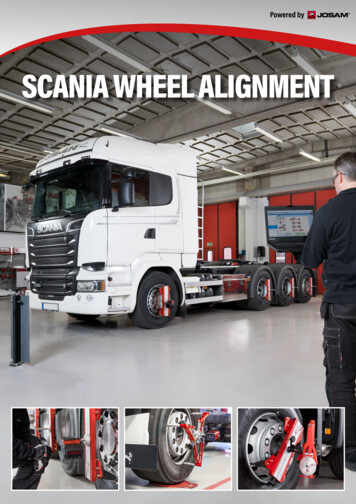
with calipers.D Diameter – The diameter ofStep-by-Step TIRE/WHEEL BALANCINGScreens with newer balancersshow inboard and outboardmeasurements automatically.Note the clip-on weight location onthe wheel flange.8. Lower the hood. The wheel willspin and unbalances are measuredand displayed. The correctiveweight amount appears in theweight display window for inboardMeasuring the rim flange ensuresselection of the proper clip-onweight.14. Attach outboard correctiveweights. Attach specified weightamount at the top-dead-center onthe outside flange of the wheel.15. Lower the hood to respin thetire/wheel and check balance. Theweight readings should now be0.00.A view of the pressure monitoringsensor being placed on the rim of thewheel.the wheel as indicated on the tire.6. For automatic measurement,pull the offset arm out to thewheel, hold it still at clip-onweight position against the wheelflange and wait for a “beep.” Re-Screen on a typical balancer prior tolowering the hood for automaticmeasurement.and outboard weight locations.9. Raise the hood after the tirestops rotating. Make sure that thewheel has stopped before raisingthe hood.10. Inboard center bar blinks. Ifan inboard corrective weight isnot required, the wheel will stopat the outboard corrective weightlocation and you can go to Step13.A, W and D dimensions on assembly.turn the arm to home position.7. Enter the wheel width dimension. Use plastic calipers to measure wheel width for manual entry.Press the W key. Use the keypad toenter width value (between 2 and20 inches.) Lower the hood for automatic measurement (see above).Note the value entry of the Wdimension.28 November 2012 TireReview11. Attach inboard correctiveweight. Attach specified weightamount at top-dead-center on theinside flange of the wheel. NOTE:Wheel weight suppliers often willsupply a rim flange contour gaugeto help technicians select the correct clip-on weight for the wheel.12. Press NEXT, causing thewheel to rotate.13. The outboard center bar willblink.Balancing In A NutshellThe balancing steps outlined inthis article are typical but will varysomewhat depending on the type ofequipment used.Recapping the steps, a technicianmust:1. Turn on the balancer2. Clean the tire, rim flangeand wheel3. Mount the tire/wheel assembly on a balancer4. Enter the A & D wheel dimensions5. Enter width wheel dimensions6. Lower the hood to spin thewheel and check dimensions7. Raise the hood after the tirestops rotating8. Note when the inboard center bar blinks9. Attach inboard correctiveweight10. Press NEXT, which rotatesthe wheel11. Note when the outboardcenter bar blinks12. Attach outboard correctiveweights13. Lower the hood to respin
A Look at Wheel Weightsand check balanceDisclaimerTire/wheel balancing is aserious business. The preceding article was researched andwritten using material furnished by Hennessy Industries, including photos anddiagrams. This information isNOT meant as a substitute forproper training by TIA, balancing equipment manufacturers or tire manufacturers.The balancing recommendations made here are consistent with practices used in theindustry when operating thistype of balancing equipment.This article is meant purelyfor educational purposes andthose who use the methodsrecommended are solely responsible for any injuries orlosses resulting from their application. Just as there are a number of assembly balancing methods, thereare a variety of weights for balancing purposes. There are standardclip-on weights of various typesthat are made to accommodate thecontours of different rim flanges.There are MC weights used on anumber of U.S. vehicles, ENweights used on VW and Honda vehicles, FN weights for Japanese vehicles and IAW weights used onmany South Korean and Europeanvehicles. A few of these types areshown in this box.There also are adhesive weightsStandard clipon weightthat are not covered in this article.They are used for custom wheels orthose that do not have an outsideflange.Additionally, there are three primary materials used to producewheel weights. Lead weights, theoriginal weights used to balanceassemblies, are making their wayout of the scene. Several stateshave outlawed lead weights – ashave the European Union andJapan – and the EPA is consideringnational action. Remaining alternatives for both clip-style and stickon weights include zinc and steel.Clip-on mass weightRapid Response: 800-928-1184 ext. 44029FN weights used onJapanese vehiclesTireReview.com 29
weight display window for inboard and outboard weight locations. 9. Raise the hood after the tire stops rotating. Make sure that the wheel has stopped before raising the hood. 10. Inboard center bar blinks. If an inboard corrective weight is not required, the wheel will stop at the outboard corrective weight location and you can- go to Step 13. 11.