Transcription
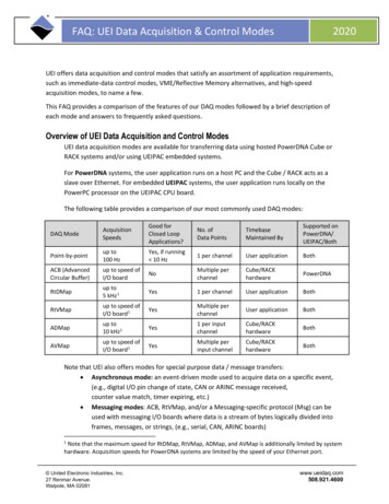
2020FAQ: UEI Data Acquisition & Control ModesUEI offers data acquisition and control modes that satisfy an assortment of application requirements,such as immediate-data control modes, VME/Reflective Memory alternatives, and high-speedacquisition modes, to name a few.This FAQ provides a comparison of the features of our DAQ modes followed by a brief description ofeach mode and answers to frequently asked questions.Overview of UEI Data Acquisition and Control ModesUEI data acquisition modes are available for transferring data using hosted PowerDNA Cube orRACK systems and/or using UEIPAC embedded systems.For PowerDNA systems, the user application runs on a host PC and the Cube / RACK acts as aslave over Ethernet. For embedded UEIPAC systems, the user application runs locally on thePowerPC processor on the UEIPAC CPU board.The following table provides a comparison of our most commonly used DAQ modes:DAQ ModeAcquisitionSpeedsGood forClosed LoopApplications?No. ofData PointsTimebaseMaintained BySupported onPowerDNA/UEIPAC/BothPoint-by-pointup to100 HzYes, if running 10 Hz1 per channelUser applicationBothACB (AdvancedCircular Buffer)up to speed ofI/O boardNoMultiple perchannelCube/RACKhardwarePowerDNARtDMapup to5 kHz 1Yes1 per channelUser applicationBothRtVMapup to speed ofI/O board1YesMultiple perchannelUser applicationBothADMapup to10 kHz1Yes1 per inputchannelCube/RACKhardwareBothAVMapup to speed ofI/O board1YesMultiple perinput channelCube/RACKhardwareBothNote that UEI also offers modes for special purpose data / message transfers: Asynchronous mode: an event-driven mode used to acquire data on a specific event,(e.g., digital I/O pin change of state, CAN or ARINC message received,counter value match, timer expiring, etc.) Messaging modes: ACB, RtVMap, and/or a Messaging-specific protocol (Msg) can beused with messaging I/O boards where data is a stream of bytes logically divided intoframes, messages, or strings, (e.g., serial, CAN, ARINC boards)1Note that the maximum speed for RtDMap, RtVMap, ADMap, and AVMap is additionally limited by systemhardware. Acquisition speeds for PowerDNA systems are limited by the speed of your Ethernet port. United Electronic Industries, Inc.27 Renmar Avenue.Walpole, MA 02081www.ueidaq.com508.921.4600
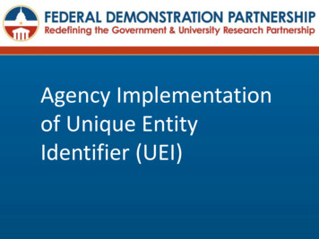
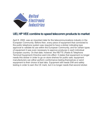
2020FAQ: UEI Data Acquisition & Control ModesHow does Point-by-point Mode work?Point-by-point mode provides easy access to asingle I/O board at a non-deterministic pace.Point-by-point mode is also referred to asImmediate mode.Using Point-by-point mode, your applicationacquires a single data point for each configuredchannel of a single I/O board.Point-by-point mode works with all UEI I/Oboards in all UEI products; however, this mode islimited to 100 Hz as the maximum acquisitionspeed.Figure 1. Input Board Using Point-by-point ModeHow does ACB Mode work?Advanced Circular Buffer (ACB) mode is abuffered data transfer protocol. ACB mode usescircular buffers for outgoing data packets and forincoming packets. Each buffer is divided intoframes, allowing a packet ring for temporary andsequential storage of received or transmittedpackets.Cube/RACK firmware issues event notification(referred to as DQE events) when incoming oroutgoing data crosses a frame boundary,initiating packet assembly and a transmission. Ifthe application detects a missing packet, itrequests retransmission.Figure 2. Input Board Using ACB ModeEvery data point is guaranteed delivery; however, because data is accumulated in a circular bufferof output or input packets, the data will have a delivery delay. For this reason, ACB mode is notappropriate for closed-loop control applications but is ideal for data acquisition applications thatrequire all data to be delivered without gaps but can accept slight delays in delivery.The ACB protocol is supported in PowerDNA systems (user application running on a host PC) butnot UEIPAC systems. UEIPACs do not require ACB mode because the user application runs on theonboard PowerPC processor; without Ethernet data transfers, lost packets are not an issue. Copyright 2020United Electronic Industries, Inc.2www.ueidaq.com508.921.4600
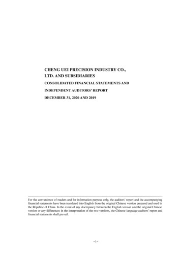
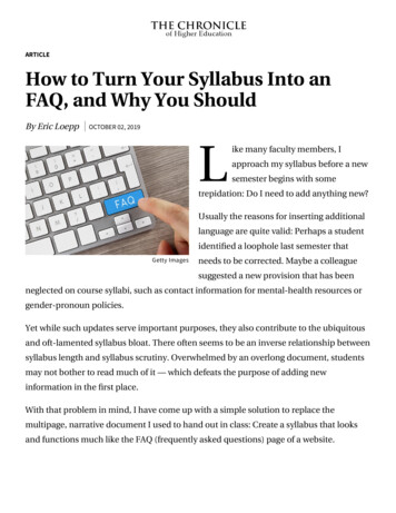
2020FAQ: UEI Data Acquisition & Control ModesHow does RtDMap Mode work?RtDMAP is designed for closed-loop (control)applications. Users set up a “map” of I/O boardsand physical channels to acquire input data fromor deliver output data to.RtDMAP optimizes transfer overhead by packingall channel data from multiple I/O boards into asingle transfer. The timebase for transferring datais maintained by the user application.Transferred data is composed of one data pointper DMAP-configured physical channel. InPowerDNA mode applications, this results intransferring a single UDP packet for all userconfigured channels, reducing network overhead.Figure 3. Input Boards Using RtDMap ModeThe maximum speed of the transfer is limited to 5000 Hz or the speed of the board.How does RtVMap Mode work?RtVMap is a data transfer protocol best used forcontrol applications.RtVMap is similar to RtDMap; however, RtVMapallows a variable number of data values to beacquired or delivered for each RtVMAPconfigured I/O channel.Similar to RtDMap, users set up a map of I/Oboards and physical channels. A timebasemaintained by the user application paces outputdata delivery from the user application, as well asrequesting input data from the Cube/RACK.Upon request, the Cube/RACK returns theRtVMAP input data, with all configured channelspacked into a single transfer. Packets can beresized dynamically to optimize bandwidth use.Figure 4. Input Boards Using RtVMap ModeThe maximum speed of the transfer is limited to the speed of the board, though in largerPowerDNA systems, the speed is also limited by Ethernet data transfer restrictions. Copyright 2020United Electronic Industries, Inc.3www.ueidaq.com508.921.4600
2020FAQ: UEI Data Acquisition & Control ModesHow does ADMap Mode work?ADMap is a data-mapped protocol best forcontrol applications and available for use withinput boards.With ADMap, users map which I/O boards andphysical channels to acquire data from for eachdata transfer; users also configure a hardwarecondition to trigger the transfer.Once the user-programmed system conditionoccurs (a condition based on a synchronizedclock or timer countdown), the UEI systemreads a single piece of channel data for allchannels configured for the ADMap. The CPUassembles the data and transfers it to the userapplication.Figure 5. Input Boards Using ADMap ModeBecause data only goes one way, the maximum transfer speed of ADMap is higher than RTDMap.How does AVMap Mode work?AVMap is a variable data-mapped protocolbest for control applications and available foruse with input boards.AVMap is similar to ADMap, except AVMAPallows users to acquire a variable number ofsamples per configured channel instead of asingle sample.With AVMap, users configure which I/Oboards and physical channels will be acquiredfor each data transfer and configure thehardware condition to trigger the transfer.Figure 6. Input Boards Using AVMap ModeOnce the user-programmed system condition occurs (a condition based on a synchronized clockor a FIFO watermark), the UEI system reads however many data samples are available from eachconfigured channel on all input boards defined in the AVMap. The data is assembled andtransferred to the user application. Copyright 2020United Electronic Industries, Inc.4www.ueidaq.com508.921.4600
FAQ: UEI Data Acquisition & Control Modes2020When should I use AXMap vs. RtXMap?Please refer to the following table to determine whether the AXMap or RtXMapprotocols better fit the requirements of your application.FEATUREAXMAPRTXMAPSupported I/O boardsInput boards onlyA variety of I/O boardsResponse timeImproved response time forapplications that need immediateoutput responses for changes in thedata (not waiting for next time frame)Best to use when there is a definedframe rate uniform to all Cube or RACKsystems on the network (or a fractionof it)Synchronization to 1PPS orIEEE-PTP source for transfersbetween hardware and appYesNoSynchronization to 1PPS orIEEE-PTP source for dataacquisition on I/O boardsYesYesInput/Output data deliverycontrolSupports input boards only; outputboards would need to be configuredas RtXMapGuaranteed that inputs are read firstand outputs are written second, soinput data is acquired in steady stateBecause AXMap doesn’t use arequest/reply scheme, it takes longerand is less reliable to recover lostPowerDNA packets.Up to 10 packets can be recovered.Uses a request/reply scheme, whichallows immediate identification of lostPowerDNA packets.Up to 10 packets can be recovered.Recoverable lost packets2Flexibility/DebugRtXMap is more flexible than AXMap, (e.g., allocates channels and data sizes in runtime for RtVMap)RtXMap is easier to debug than AXMap (e.g., control is via user application)2Note that the lost packet rate on a “typical” network is between 1 in 1,000,00 and 1 in10,000,000. Loss of packets more frequently than that often indicates a network problem. Copyright 2020United Electronic Industries, Inc.5www.ueidaq.com508.921.4600
FAQ: UEI Data Acquisition & Control ModesHow does Asynchronous mode work?Asynchronous mode is similar to ADMap,except that the data packets are sent upon auser-programmable asynchronous event.Users configure which physical channels toacquire data from for the data transfers andprogram a hardware condition to trigger thetransfer.Once the system condition occurs, the UEICube/RACK reads a single piece of channeldata for each configured channel. The CPUassembles the data and transfers the packetto the user application.Figure 7. Input Board Using Asynchronous ModeThe following table lists I/O boards that support Asynchronous mode and which typesof events they support:TYPE OF I/O BOARDTYPE OF ASYNCHRONOUS EVENTSEXAMPLES OF SUPPORTED BOARDSDigital I/O BoardsEdge detection/Change of state, andPeriodic EventsDNx-DIO-401/3/4/5/6,DNx-DIO-449Serial I/O BoardsTimeout conditions, TX done, RX done,and pattern detection EventsDNx-SL-501, DNx-SL-508CAN-Bus BoardsFIFO watermark and bus error EventsDNx-CAN-503Counter/Timer BoardsCount complete, edge detection oninput and/or gate pin EventsDNx-CT-601, DNx-CT-602IRIG-650 Boards1PPS and GPS data ready EventsDNx-IRIG-650Avionics Protocol BoardsMany protocol-specific EventsDNx-1553-553, DNx-AFDX-664 Copyright 2020United Electronic Industries, Inc.6www.ueidaq.com508.921.46002020
2020FAQ: UEI Data Acquisition & Control ModesHow do I get started with each of the modes?Using UEI-provided sample code is the best way to get started when programming each of theDAQ modes.UEI provides object-oriented Framework samples for programming in C , C#, .Net, MATLAB,LabView, and many more. Framework is available when using Windows OS and specificallysupports Point-by-point and ACB (buffered) modes.UEI also provides C-based sample code when programming low-level applications (using WindowsOS, Linux OS, or VxWorks OS).All UEI software installations include an extensive set of code samples.Are all modes available for all products?Acquisition modes are I/O board-specific. Users can check the examples repository to see whichI/O boards have sample programs supporting specific acquisition modes. Point-by-point mode issupported for all I/O boards.Additionally, note that UEIPAC systems specifically support Point-by-point, RtDMap, RtVMap,AVMap, and ADMap modes (not ACB).When deciding which acquisition mode to use, UEI support is happy to help guide you indetermining which I/O mode is best suited for your application.For more information:Please contact UEI support at support@ueidaq.com or call 508.921.4600 with any questions. Copyright 2020United Electronic Industries, Inc.7www.ueidaq.com508.921.4600
FAQ: UEI Data Acquisition & Control Modes 2020 How do I get started with each of the modes? Using UEI-provided sample code is the best way to get started when programming each of the DAQ modes. UEI provides object-oriented Framework samples for programming in C , C#, .Net, MATLAB, LabView, and many more.